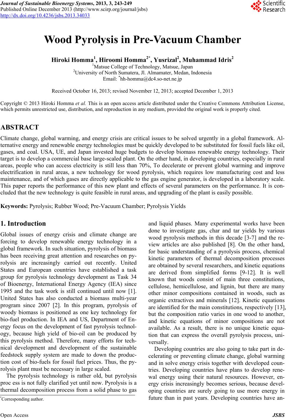
 Journal of Sustainable Bioenergy Systems, 2013, 3, 243-249 Published Online December 2013 (http://www.scirp.org/journal/jsbs) http://dx.doi.org/10.4236/jsbs.2013.34033 Open Access JSBS Wood Pyrolysis in Pre-Vacuum Chamber Hiroki Homma1, Hiroomi Homma2*, Yusrizal2, Muhammad Idris2 1Matsue College of Technology, Matsue, Japan 2University of North Sumatera, Jl. Almamater, Medan, Indonesia Email: *hh-homma@dc4.so-net.ne.jp Received October 16, 2013; revised November 12, 2013; accepted December 1, 2013 Copyright © 2013 Hiroki Homma et al. This is an open access article distributed under the Creative Commons Attribution License, which permits unrestricted use, distribution, and reproduction in any medium, provided the original work is properly cited. ABSTRACT Climate change, global warming, and energy crisis are critical issues to be solved urgently in a global framework. Al- ternative energy and renewable energy technologies must be quickly developed to be substituted for fossil fuels like oil, gases, and coal. USA, UE, and Japan invested huge budgets to develop biomass renewable energy technology. Their target is to develop a commercial base large-scaled plant. On the other hand, in developing countries, especially in rural areas, people who can access electricity is still less than 70%, To decelerate or prevent global warming and improve electrification in rural areas, a new technology for wood pyrolysis, which requires low manufacturing cost and less maintenance, and of which gases are directly applicable to the gas engine generator, is developed in a laboratory scale. This paper reports the performance of this new plant and effects of several parameters on the performance. It is con- cluded that the new technology is quite feasible in rural areas, and upgrading of the plant is easily possible. Keywords: Pyrolysis; Rubber Wood; Pre-Vacuum Chamber; Pyrolysis Yields 1. Introduction Global issues of energy crisis and climate change are forcing to develop renewable energy technology in a global framework. In such situation, pyrolysis of biomass has been receiving great attention and researches on py- rolysis are increasingly carried out recently. United States and European countries have established a task group for pyrolysis technology development as Task 34 of Bioenergy, International Energy Agency (IEA) since 1995 and the task work is still continued until now [1]. United States has also conducted a biomass multi-year program since 2007 [2]. In this program, pyrolysis of woody biomass is positioned as one key technology for bio-fuel production. In IEA and US, Department of En- ergy focus on the development of fast pyrolysis technol- ogy, because high yield of bio-oil can be produced by this pyrolysis method. Therefore, many efforts for tech- nical development and development of the sustainable feedstock supply system are made to down the produc- tion cost of bio-fuels for fossil fuel prices. Thus, the py- rolysis plant must be necessary in large scaled. The pyrolysis technology is rather old, but pyrolysis proc ess is not fully clarified yet until now. Pyrolysis is a thermal decomposition process from a solid phase to gas and liquid phases. Many experimental works have been done to investigate gas, char and tar yields by various wood pyrolysis methods in this decade [3-7] and the re- view articles are also published [8]. On the other hand, for basic understanding of a pyrolysis process, chemical kinetic parameters of thermal decomposition processes are obtained by several researchers, and kinetic equations are derived from simplified forms [9-12]. It is well known that woods consist of main three constitutions, cellulose, hemicellulose, and lignin, but there are many other minor compositions contained in woods, such as organic extractives and minerals [12]. Kinetic equations are identified for the main constitutions, respectively [13], but the composition ratio varies in one wood to another, and kinetic equations of minor compositions are not available. As a result, there is no unique kinetic equa- tion that can express the overall pyrolysis process, uni- versally. Developing countries are also going to take part in de- celerating or preventing climate change, global warming and in solve energy crisis together with developed coun- tries. Developing countries have plans to develop rene- wal energy using their natural resources. However, en- ergy crisis increasingly becomes serious, because devel- oping countries are surely going to use more energy in future than in past years. Developing countries have an- *Corresponding author. 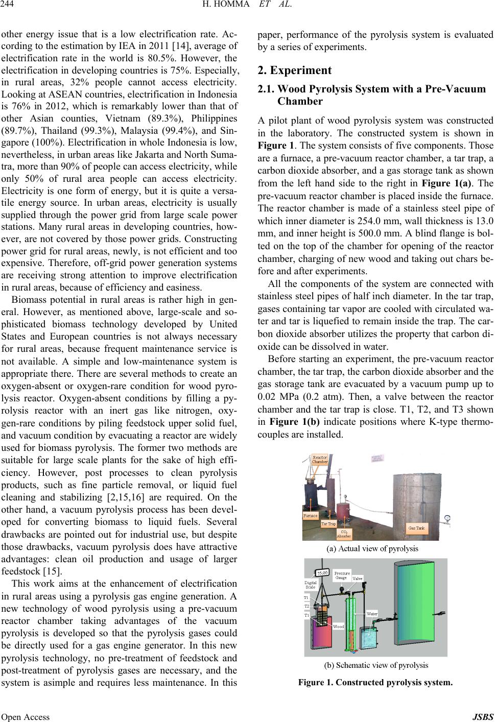 H. HOMMA ET AL. 244 other energy issue that is a low electrification rate. Ac- cording to the estimation by IEA in 2011 [14], average of electrification rate in the world is 80.5%. However, the electrification in developing countries is 75%. Especially, in rural areas, 32% people cannot access electricity. Looking at ASEAN countries, electrification in Indonesia is 76% in 2012, which is remarkably lower than that of other Asian counties, Vietnam (89.3%), Philippines (89.7%), Thailand (99.3%), Malaysia (99.4%), and Sin- gapore (100%). Electrification in whole Indonesia is low, nevertheless, in urban areas like Jakarta and North Suma- tra, more than 90% of people can access electricity, while only 50% of rural area people can access electricity. Electricity is one form of energy, but it is quite a versa- tile energy source. In urban areas, electricity is usually supplied through the power grid from large scale power stations. Many rural areas in developing countries, how- ever, are not covered by those power grids. Constructing power grid for rural areas, newly, is not efficient and too expensive. Therefore, off-grid power generation systems are receiving strong attention to improve electrification in rural areas, because of efficiency and easiness. Biomass potential in rural areas is rather high in gen- eral. However, as mentioned above, large-scale and so- phisticated biomass technology developed by United States and European countries is not always necessary for rural areas, because frequent maintenance service is not available. A simple and low-maintenance system is appropriate there. There are several methods to create an oxygen-absent or oxygen-rare condition for wood pyro- lysis reactor. Oxygen-absent conditions by filling a py- rolysis reactor with an inert gas like nitrogen, oxy- gen-rare conditions by piling feedstock upper solid fuel, and vacuum condition by evacuating a reactor are widely used for biomass pyrolysis. The former two methods are suitable for large scale plants for the sake of high effi- ciency. However, post processes to clean pyrolysis products, such as fine particle removal, or liquid fuel cleaning and stabilizing [2,15,16] are required. On the other hand, a vacuum pyrolysis process has been devel- oped for converting biomass to liquid fuels. Several drawbacks are pointed out for industrial use, but despite those drawbacks, vacuum pyrolysis does have attractive advantages: clean oil production and usage of larger feedstock [15]. This work aims at the enhancement of electrification in rural areas using a pyrolysis gas engine generation. A new technology of wood pyrolysis using a pre-vacuum reactor chamber taking advantages of the vacuum pyrolysis is developed so that the pyrolysis gases could be directly used for a gas engine generator. In this new pyrolysis technology, no pre-treatment of feedstock and post-treatment of pyrolysis gases are necessary, and the system is asimple and requires less maintenance. In this paper, performance of the pyrolysis system is evaluated by a series of experiments. 2. Experiment 2.1. Wood Pyrolysis System with a Pre-Vacuum Chamber A pilot plant of wood pyrolysis system was constructed in the laboratory. The constructed system is shown in Figure 1. The system consists of five components. Those are a furnace, a pre-vacuum reactor chamber, a tar trap, a carbon dioxide absorber, and a gas storage tank as shown from the left hand side to the right in Figure 1(a). The pre-vacuum reactor chamber is placed inside the furnace. The reactor chamber is made of a stainless steel pipe of which inner diameter is 254.0 mm, wall thickness is 13.0 mm, and inner height is 500.0 mm. A blind flange is bol- ted on the top of the chamber for opening of the reactor chamber, charging of new wood and taking out chars be- fore and after experiments. All the components of the system are connected with stainless steel pipes of half inch diameter. In the tar trap, gases containing tar vapor are cooled with circulated wa- ter and tar is liquefied to remain inside the trap. The car- bon dioxide absorber utilizes the property that carbon di- oxide can be dissolved in water. Before starting an experiment, the pre-vacuum reactor chamber, the tar trap, the carbon dioxide absorber and the gas storage tank are evacuated by a vacuum pump up to 0.02 MPa (0.2 atm). Then, a valve between the reactor chamber and the tar trap is close. T1, T2, and T3 shown in Figure 1(b) indicate positions where K-type thermo- couples are installed. Figure 1. Constructed pyroly sis system. Open Access JSBS 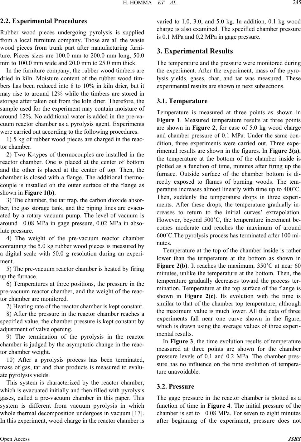 H. HOMMA ET AL. 245 2.2. Experimental Procedures Rubber wood pieces undergoing pyrolysis is supplied from a local furniture company. Those are all the waste wood pieces from trunk part after manufacturing furni- ture. Pieces sizes are 100.0 mm to 200.0 mm long, 50.0 mm to 100.0 mm wide and 20.0 mm to 25.0 mm thick. In the furniture company, the rubber wood timbers are dried in kiln. Moisture content of the rubber wood tim- bers has been reduced into 8 to 10% in kiln drier, but it may rise to around 12% while the timbers are stored in storage after taken out from the kiln drier. Therefore, the sample used for the experiment may contain moisture of around 12%. No additional water is added in the pre-va- cuum reactor chamber as a pyrolysis agent. Experiments were carried out according to the following procedures. 1) 5 kg of rubber wood pieces are charged in the reac- tor chamber. 2) Two K-types of thermocouples are installed in the reactor chamber. One is placed at the center of bottom and the other is placed at the center of top. Then, the chamber is closed with a flange. The additional thermo- couple is installed on the outer surface of the flange as shown in Figure 1(b). 3) The chamber, the tar trap, the carbon dioxide absor- ber, the gas storage tank, and the piping lines are evacu- ated by a rotary vacuum pump. The level of vacuum is around −0.08 MPa in gage pressure, 0.02 MPa in abso- lute pressure. 4) The weight of the pre-vacuum reactor chamber containing the 5.0 kg rubber wood pieces is measured by a digital scale with 50.0 g resolution during an experi- ment. 5) The pre-vacuum reactor chamber is heated by firing up the furnace. 6) Temperatures at three positions, the pressure in the pre-vacuum reactor chamber, and the weight of the reac- tor chamber are monitored. 7) Heating rate of the reactor chamber is kept constant. 8) After the pressure in the reactor chamber reaches a specified value, the chamber pressure is kept constant by adjustment of valve opening. 9) The termination of the pyrolysis in the reactor chamber is judged by the asymptotic change in the reac- tor chamber weight. 10) After a pyrolysis process has been terminated, mass of gas, tar and char products is measured to evalu- ate pyrolysis yields. This system is characterized by the reactor chamber, which is evacuated initially and then filled with pyrolysis gases, called a pre-vacuum chamber in this paper. This system is different from vacuum pyrolysis in which whole thermal decomposition undergoes in vacuum [17]. In this experiment, wood charge in the reactor chamber is varied to 1.0, 3.0, and 5.0 kg. In addition, 0.1 kg wood charge is also examined. The specified chamber pressure is 0.1 MPa and 0.2 MPa in gage pressure. 3. Experimental Results The temperature and the pressure were monitored during the experiment. After the experiment, mass of the pyro- lysis yields, gases, char, and tar was measured. These experimental results are shown in next subsections. 3.1. Temperature Temperature is measured at three points as shown in Figure 1. Measured temperature results at three points are shown in Figure 2, for case of 5.0 kg wood charge and chamber pressure of 0.1 MPa. Under the same con- dition, three experiments were carried out. Three expe- rimental results are shown in the figures. In Figure 2(a), the temperature at the bottom of the chamber inside is plotted as a function of time, minutes after firing up the furnace. Outside surface of the chamber bottom is di- rectly exposed to flames of burning woods. The tem- perature increases almost linearly with time up to 400˚C. Then, suddenly the temperature drops in three experi- ments. After these drops, the temperature gradually in- creases to return to the initial curves’ extrapolation. However, beyond 500˚C, the temperature increment be- comes moderate and reaches the maximum of around 600˚C.The pyrolysis process has terminated after 100 mi- nutes. Temperature at the top of the chamber inside is rather lower than the temperature at the bottom as shown in Figure 2(b). It reaches the maximum, 350˚C at near 60 minutes, unlike the temperature at the bottom. Then, the temperature gradually decreases toward the process ter- mination. Temperature at the top surface of the flange is shown in Figure 2(c). Its evolution with the time is similar to that of the chamber top temperature, although the maximum value is much lower. All the data of three experiments fall near one curve shown in the figure, which is drawn using the average values of three experi- mental results. In Figure 3, the time evolution results of temperature measured at three points are shown for the chamber pressure levels of 0.1 and 0.2 MPa. The chamber pres- sure has no influence on the time evolution of tempera- ture unavoidable. 3.2. Pressure The gage pressure in the reactor chamber is plotted as a function of time in Figure 4. The initial pressure of the chamber is set to −0.08 MPa. For seven to eight minutes after beginning of the experiment, pressure does not Open Access JSBS 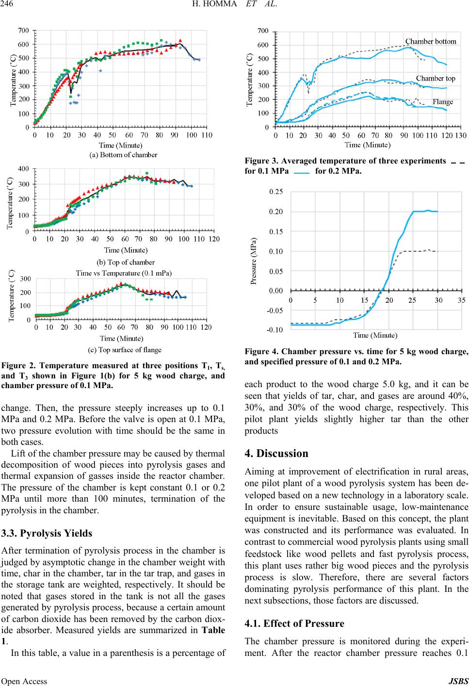 H. HOMMA ET AL. 246 Figure 2. Temperature measured at three positions T1, Ts, and T3 shown in Figure 1(b) for 5 kg wood charge, and chamber pressure of 0.1 MPa. change. Then, the pressure steeply increases up to 0.1 MPa and 0.2 MPa. Before the valve is open at 0.1 MPa, two pressure evolution with time should be the same in both cases. Lift of the chamber pressure may be caused by thermal decomposition of wood pieces into pyrolysis gases and thermal expansion of gasses inside the reactor chamber. The pressure of the chamber is kept constant 0.1 or 0.2 MPa until more than 100 minutes, termination of the pyrolysis in the chamber. 3.3. Pyrolysis Yields After termination of pyrolysis process in the chamber is judged by asymptotic change in the chamber weight with time, char in the chamber, tar in the tar trap, and gases in the storage tank are weighted, respectively. It should be noted that gases stored in the tank is not all the gases generated by pyrolysis process, because a certain amount of carbon dioxide has been removed by the carbon diox- ide absorber. Measured yields are summarized in Table 1. In this table, a value in a parenthesis is a percentage of Figure 3. Averaged temperature of three experiments for 0.1 MPa for 0.2 MPa. Figure 4. Chamber pressure vs. time for 5 kg wood charge, and specified pressure of 0.1 and 0.2 MPa. each product to the wood charge 5.0 kg, and it can be seen that yields of tar, char, and gases are around 40%, 30%, and 30% of the wood charge, respectively. This pilot plant yields slightly higher tar than the other products 4. Discussion Aiming at improvement of electrification in rural areas, one pilot plant of a wood pyrolysis system has been de- veloped based on a new technology in a laboratory scale. In order to ensure sustainable usage, low-maintenance equipment is inevitable. Based on this concept, the plant was constructed and its performance was evaluated. In contrast to commercial wood pyrolysis plants using small feedstock like wood pellets and fast pyrolysis process, this plant uses rather big wood pieces and the pyrolysis process is slow. Therefore, there are several factors dominating pyrolysis performance of this plant. In the next subsections, those factors are discussed. 4.1. Effect of Pressure The chamber pressure is monitored during the experi- ment. After the reactor chamber pressure reaches 0.1 Open Access JSBS 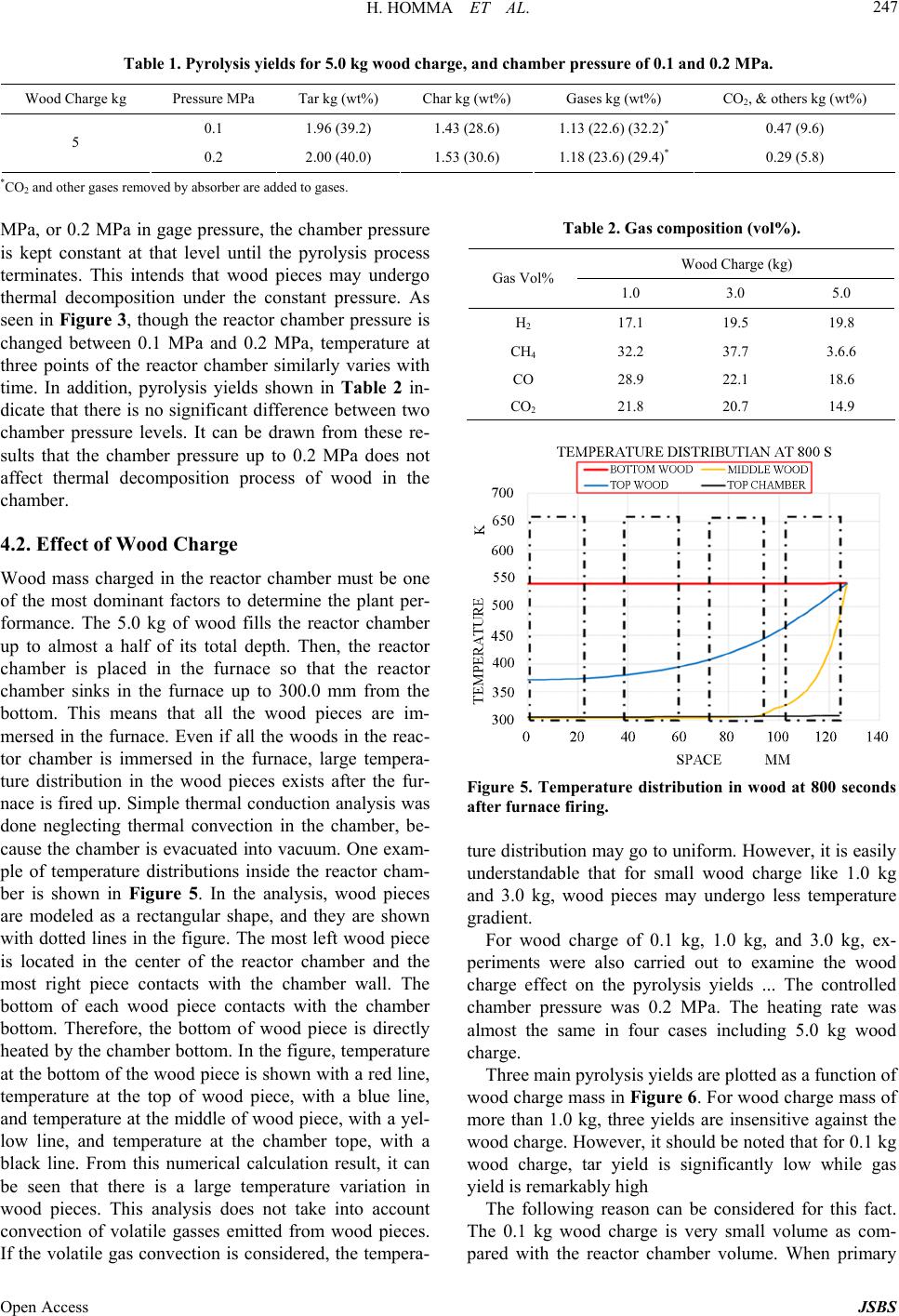 H. HOMMA ET AL. Open Access JSBS 247 Table 1. Pyrolysis yields for 5.0 kg wood charge, and chamber pressure of 0.1 and 0.2 MPa. Wood Charge kg Pressure MPa Tar kg (wt%) Char kg (wt%) Gases kg (wt%) CO2, & others kg (wt%) 0.1 1.96 (39.2) 1.43 (28.6) 1.13 (22.6) (32.2)* 0.47 (9.6) 5 0.2 2.00 (40.0) 1.53 (30.6) 1.18 (23.6) (29.4)* 0.29 (5.8) *CO2 and other gases removed by absorber are added to gases. Table 2. Gas composition (vol%). MPa, or 0.2 MPa in gage pressure, the chamber pressure is kept constant at that level until the pyrolysis process terminates. This intends that wood pieces may undergo thermal decomposition under the constant pressure. As seen in Figure 3, though the reactor chamber pressure is changed between 0.1 MPa and 0.2 MPa, temperature at three points of the reactor chamber similarly varies with time. In addition, pyrolysis yields shown in Table 2 in- dicate that there is no significant difference between two chamber pressure levels. It can be drawn from these re- sults that the chamber pressure up to 0.2 MPa does not affect thermal decomposition process of wood in the chamber. Wood Charge (kg) Gas Vol% 1.0 3.0 5.0 H2 17.1 19.5 19.8 CH4 32.2 37.7 3.6.6 CO 28.9 22.1 18.6 CO2 21.8 20.7 14.9 4.2. Effect of Wood Charge Wood mass charged in the reactor chamber must be one of the most dominant factors to determine the plant per- formance. The 5.0 kg of wood fills the reactor chamber up to almost a half of its total depth. Then, the reactor chamber is placed in the furnace so that the reactor chamber sinks in the furnace up to 300.0 mm from the bottom. This means that all the wood pieces are im- mersed in the furnace. Even if all the woods in the reac- tor chamber is immersed in the furnace, large tempera- ture distribution in the wood pieces exists after the fur- nace is fired up. Simple thermal conduction analysis was done neglecting thermal convection in the chamber, be- cause the chamber is evacuated into vacuum. One exam- ple of temperature distributions inside the reactor cham- ber is shown in Figure 5. In the analysis, wood pieces are modeled as a rectangular shape, and they are shown with dotted lines in the figure. The most left wood piece is located in the center of the reactor chamber and the most right piece contacts with the chamber wall. The bottom of each wood piece contacts with the chamber bottom. Therefore, the bottom of wood piece is directly heated by the chamber bottom. In the figure, temperature at the bottom of the wood piece is shown with a red line, temperature at the top of wood piece, with a blue line, and temperature at the middle of wood piece, with a yel- low line, and temperature at the chamber tope, with a black line. From this numerical calculation result, it can be seen that there is a large temperature variation in wood pieces. This analysis does not take into account convection of volatile gasses emitted from wood pieces. If the volatile gas convection is considered, the tempera- Figure 5. Temperature distribution in wood at 800 seconds after furnac e firing. ture distribution may go to uniform. However, it is easily understandable that for small wood charge like 1.0 kg and 3.0 kg, wood pieces may undergo less temperature gradient. For wood charge of 0.1 kg, 1.0 kg, and 3.0 kg, ex- periments were also carried out to examine the wood charge effect on the pyrolysis yields ... The controlled chamber pressure was 0.2 MPa. The heating rate was almost the same in four cases including 5.0 kg wood charge. Three main pyrolysis yields are plotted as a function of wood charge mass in Figure 6. For wood charge mass of more than 1.0 kg, three yields are insensitive against the wood charge. However, it should be noted that for 0.1 kg wood charge, tar yield is significantly low while gas yield is remarkably high The following reason can be considered for this fact. The 0.1 kg wood charge is very small volume as com- pared with the reactor chamber volume. When primary 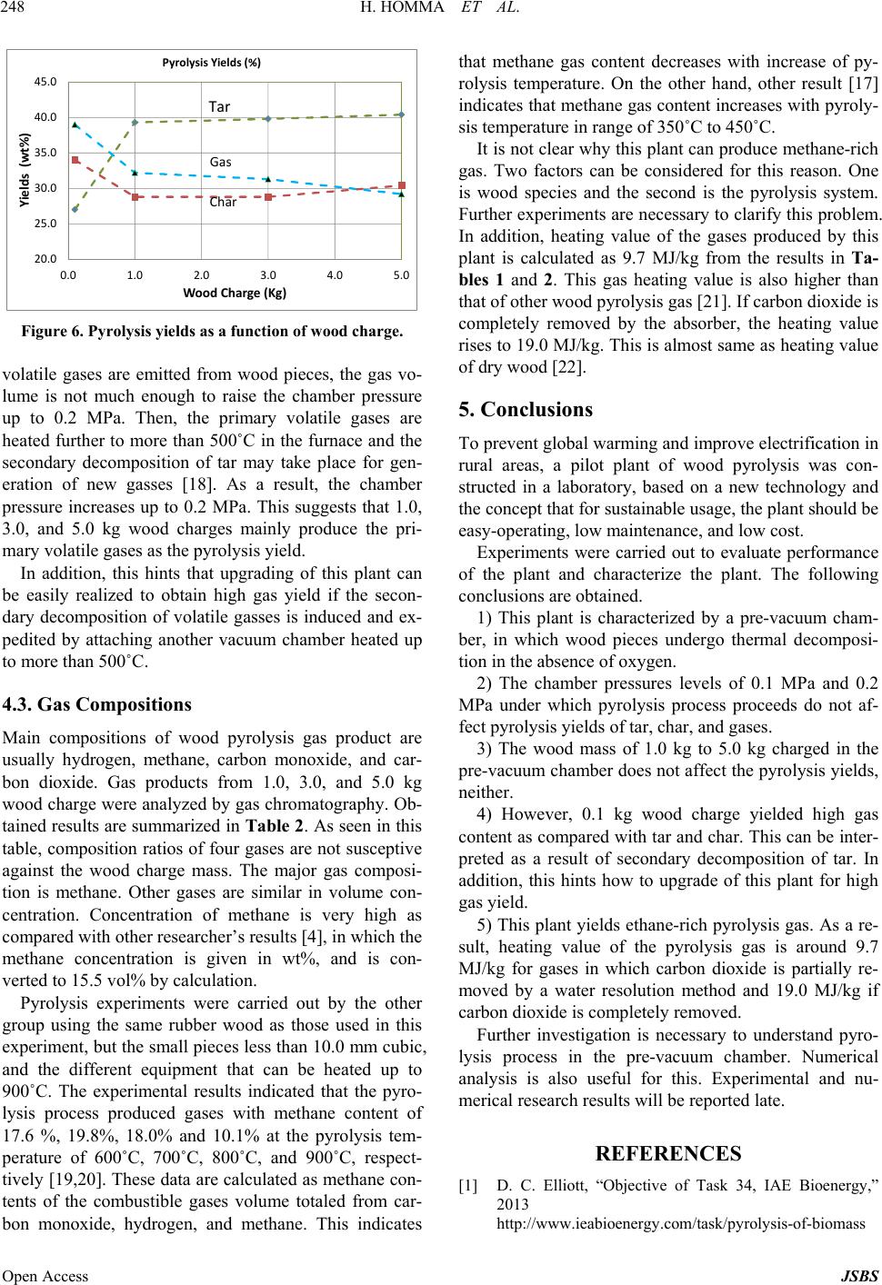 H. HOMMA ET AL. 248 20.0 25.0 30.0 35.0 40.0 45.0 0.0 1.0 2.0 3.0 4.0 5.0 Yields(wt%) WoodCharge (Kg) PyrolysisYields (%) Tar Gas Char Figure 6. Pyrolysis yields as a function of wood charge. volatile gases are emitted from wood pieces, the gas vo- lume is not much enough to raise the chamber pressure up to 0.2 MPa. Then, the primary volatile gases are heated further to more than 500˚C in the furnace and the secondary decomposition of tar may take place for gen- eration of new gasses [18]. As a result, the chamber pressure increases up to 0.2 MPa. This suggests that 1.0, 3.0, and 5.0 kg wood charges mainly produce the pri- mary volatile gases as the pyrolysis yield. In addition, this hints that upgrading of this plant can be easily realized to obtain high gas yield if the secon- dary decomposition of volatile gasses is induced and ex- pedited by attaching another vacuum chamber heated up to more than 500˚C. 4.3. Gas Compositions Main compositions of wood pyrolysis gas product are usually hydrogen, methane, carbon monoxide, and car- bon dioxide. Gas products from 1.0, 3.0, and 5.0 kg wood charge were analyzed by gas chromatography. Ob- tained results are summarized in Ta ble 2 . As seen in this table, composition ratios of four gases are not susceptive against the wood charge mass. The major gas composi- tion is methane. Other gases are similar in volume con- centration. Concentration of methane is very high as compared with other researcher’s results [4], in which the methane concentration is given in wt%, and is con- verted to 15.5 vol% by calculation. Pyrolysis experiments were carried out by the other group using the same rubber wood as those used in this experiment, but the small pieces less than 10.0 mm cubic, and the different equipment that can be heated up to 900˚C. The experimental results indicated that the pyro- lysis process produced gases with methane content of 17.6 %, 19.8%, 18.0% and 10.1% at the pyrolysis tem- perature of 600˚C, 700˚C, 800˚C, and 900˚C, respect- tively [19,20]. These data are calculated as methane con- tents of the combustible gases volume totaled from car- bon monoxide, hydrogen, and methane. This indicates that methane gas content decreases with increase of py- rolysis temperature. On the other hand, other result [17] indicates that methane gas content increases with pyroly- sis temperature in range of 350˚C to 450˚C. It is not clear why this plant can produce methane-rich gas. Two factors can be considered for this reason. One is wood species and the second is the pyrolysis system. Further experiments are necessary to clarify this problem. In addition, heating value of the gases produced by this plant is calculated as 9.7 MJ/kg from the results in Ta- bles 1 and 2. This gas heating value is also higher than that of other wood pyrolysis gas [21]. If carbon dioxide is completely removed by the absorber, the heating value rises to 19.0 MJ/kg. This is almost same as heating value of dry wood [22]. 5. Conclusions To prevent global warming and improve electrification in rural areas, a pilot plant of wood pyrolysis was con- structed in a laboratory, based on a new technology and the concept that for sustainable usage, the plant should be easy-operating, low maintenance, and low cost. Experiments were carried out to evaluate performance of the plant and characterize the plant. The following conclusions are obtained. 1) This plant is characterized by a pre-vacuum cham- ber, in which wood pieces undergo thermal decomposi- tion in the absence of oxygen. 2) The chamber pressures levels of 0.1 MPa and 0.2 MPa under which pyrolysis process proceeds do not af- fect pyrolysis yields of tar, char, and gases. 3) The wood mass of 1.0 kg to 5.0 kg charged in the pre-vacuum chamber does not affect the pyrolysis yields, neither. 4) However, 0.1 kg wood charge yielded high gas content as compared with tar and char. This can be inter- preted as a result of secondary decomposition of tar. In addition, this hints how to upgrade of this plant for high gas yield. 5) This plant yields ethane-rich pyrolysis gas. As a re- sult, heating value of the pyrolysis gas is around 9.7 MJ/kg for gases in which carbon dioxide is partially re- moved by a water resolution method and 19.0 MJ/kg if carbon dioxide is completely removed. Further investigation is necessary to understand pyro- lysis process in the pre-vacuum chamber. Numerical analysis is also useful for this. Experimental and nu- merical research results will be reported late. REFERENCES [1] D. C. Elliott, “Objective of Task 34, IAE Bioenergy,” 2013 http://www.ieabioenergy.com/task/pyrolysis-of-biomass Open Access JSBS 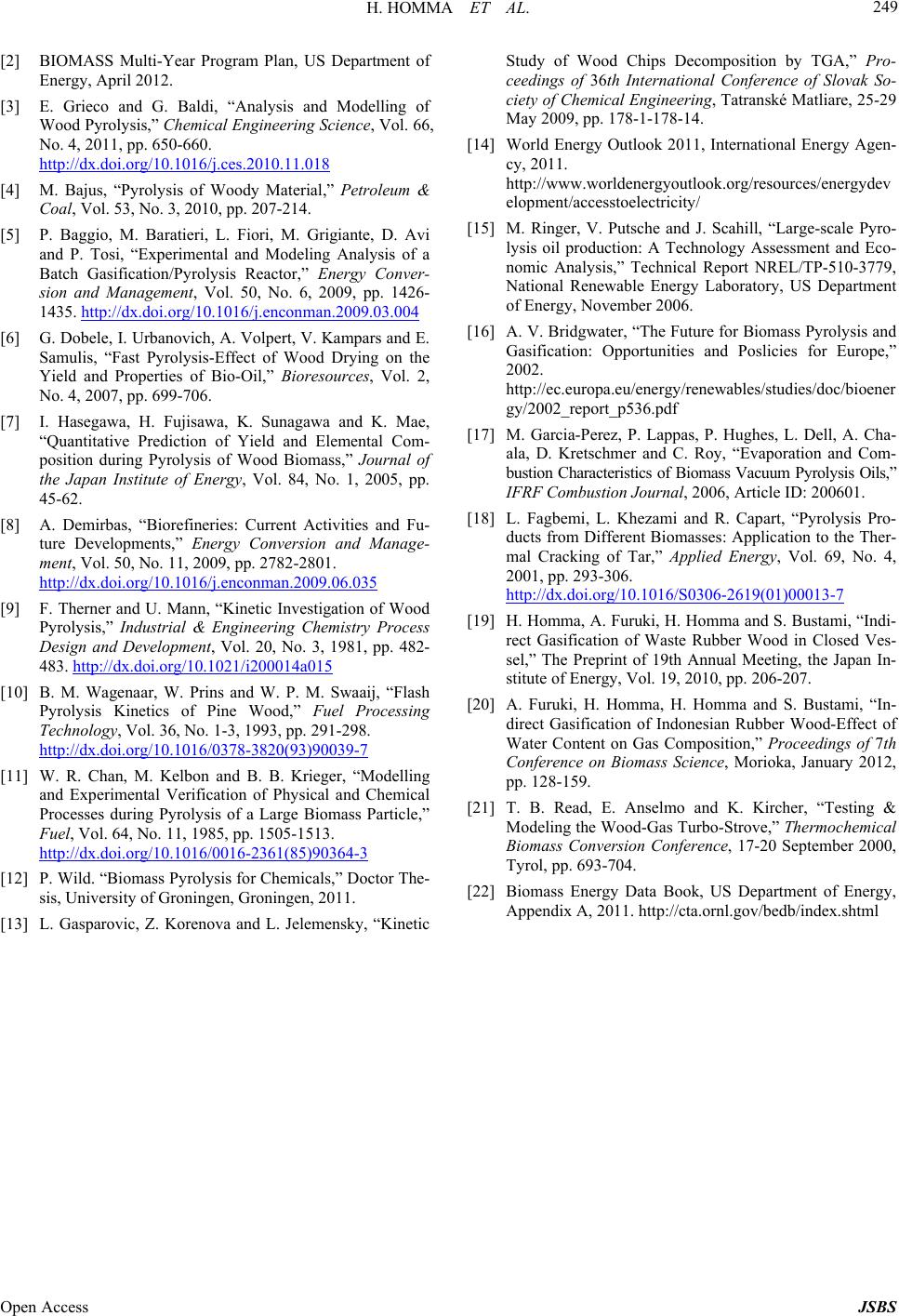 H. HOMMA ET AL. Open Access JSBS 249 [2] BIOMASS Multi-Year Program Plan, US Department of Energy, April 2012. [3] E. Grieco and G. Baldi, “Analysis and Modelling of Wood Pyrolysis,” Chemical Engineering Science, Vol. 66, No. 4, 2011, pp. 650-660. http://dx.doi.org/10.1016/j.ces.2010.11.018 [4] M. Bajus, “Pyrolysis of Woody Material,” Petroleum & Coal, Vol. 53, No. 3, 2010, pp. 207-214. [5] P. Baggio, M. Baratieri, L. Fiori, M. Grigiante, D. Avi and P. Tosi, “Experimental and Modeling Analysis of a Batch Gasification/Pyrolysis Reactor,” Energy Conver- sion and Management, Vol. 50, No. 6, 2009, pp. 1426- 1435. http://dx.doi.org/10.1016/j.enconman.2009.03.004 [6] G. Dobele, I. Urbanovich, A. Volpert, V. Kampars and E. Samulis, “Fast Pyrolysis-Effect of Wood Drying on the Yield and Properties of Bio-Oil,” Bioresources, Vol. 2, No. 4, 2007, pp. 699-706. [7] I. Hasegawa, H. Fujisawa, K. Sunagawa and K. Mae, “Quantitative Prediction of Yield and Elemental Com- position during Pyrolysis of Wood Biomass,” Journal of the Japan Institute of Energy, Vol. 84, No. 1, 2005, pp. 45-62. [8] A. Demirbas, “Biorefineries: Current Activities and Fu- ture Developments,” Energy Conversion and Manage- ment, Vol. 50, No. 11, 2009, pp. 2782-2801. http://dx.doi.org/10.1016/j.enconman.2009.06.035 [9] F. Therner and U. Mann, “Kinetic Investigation of Wood Pyrolysis,” Industrial & Engineering Chemistry Process Design and Development, Vol. 20, No. 3, 1981, pp. 482- 483. http://dx.doi.org/10.1021/i200014a015 [10] B. M. Wagenaar, W. Prins and W. P. M. Swaaij, “Flash Pyrolysis Kinetics of Pine Wood,” Fuel Processing Technology, Vol. 36, No. 1-3, 1993, pp. 291-298. http://dx.doi.org/10.1016/0378-3820(93)90039-7 [11] W. R. Chan, M. Kelbon and B. B. Krieger, “Modelling and Experimental Verification of Physical and Chemical Processes during Pyrolysis of a Large Biomass Particle,” Fuel, Vol. 64, No. 11, 1985, pp. 1505-1513. http://dx.doi.org/10.1016/0016-2361(85)90364-3 [12] P. Wild. “Biomass Pyrolysis for Chemicals,” Doctor The- sis, University of Groningen, Groningen, 2011. [13] L. Gasparovic, Z. Korenova and L. Jelemensky, “Kinetic Study of Wood Chips Decomposition by TGA,” Pro- ceedings of 36th International Conference of Slovak So- ciety of Chemical Engineering, Tatranské Matliare, 25-29 May 2009, pp. 178-1-178-14. [14] World Energy Outlook 2011, International Energy Agen- cy, 2011. http://www.worldenergyoutlook.org/resources/energydev elopment/accesstoelectricity/ [15] M. Ringer, V. Putsche and J. Scahill, “Large-scale Pyro- lysis oil production: A Technology Assessment and Eco- nomic Analysis,” Technical Report NREL/TP-510-3779, National Renewable Energy Laboratory, US Department of Energy, November 2006. [16] A. V. Bridgwater, “The Future for Biomass Pyrolysis and Gasification: Opportunities and Poslicies for Europe,” 2002. http://ec.europa.eu/energy/renewables/studies/doc/bioener gy/2002_report_p536.pdf [17] M. Garcia-Perez, P. Lappas, P. Hughes, L. Dell, A. Cha- ala, D. Kretschmer and C. Roy, “Evaporation and Com- bustion Characteristics of Biomass Vacuum Pyrolysis Oils,” IFRF Combustion Journal, 2006, Article ID: 200601. [18] L. Fagbemi, L. Khezami and R. Capart, “Pyrolysis Pro- ducts from Different Biomasses: Application to the Ther- mal Cracking of Tar,” Applied Energy, Vol. 69, No. 4, 2001, pp. 293-306. http://dx.doi.org/10.1016/S0306-2619(01)00013-7 [19] H. Homma, A. Furuki, H. Homma and S. Bustami, “Indi- rect Gasification of Waste Rubber Wood in Closed Ves- sel,” The Preprint of 19th Annual Meeting, the Japan In- stitute of Energy, Vol. 19, 2010, pp. 206-207. [20] A. Furuki, H. Homma, H. Homma and S. Bustami, “In- direct Gasification of Indonesian Rubber Wood-Effect of Water Content on Gas Composition,” Proceedings of 7th Conference on Biomass Science, Morioka, January 2012, pp. 128-159. [21] T. B. Read, E. Anselmo and K. Kircher, “Testing & Modeling the Wood-Gas Turbo-Strove,” Thermochemical Biomass Conversion Conference, 17-20 September 2000, Tyrol, pp. 693-704. [22] Biomass Energy Data Book, US Department of Energy, Appendix A, 2011. http://cta.ornl.gov/bedb/index.shtml
|