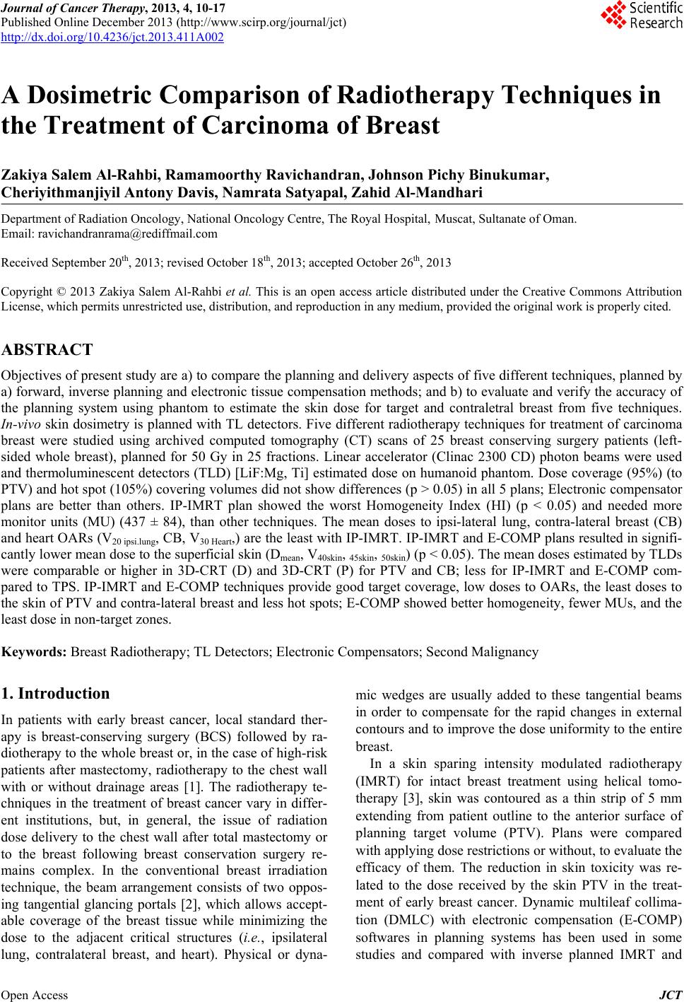
 Journal of Cancer Therapy, 2013, 4, 10-17 Published Online December 2013 (http://www.scirp.org/journal/jct) http://dx.doi.org/10.4236/jct.2013.411A002 Open Access JCT A Dosimetric Comparison of Radiotherapy Techniques in the Treatment of Carcinoma of Breast Zakiya Salem Al-Rahbi, Ramamoorthy Ravichandran, Johnson Pichy Binukumar, Cheriyithmanjiyil Antony Davis, Namrata Satyapal, Zahid Al-Mandhari Department of Radiation Oncology, National Oncology Centre, The Royal Hospital, Muscat, Sultanate of Oman. Email: ravichandranrama@rediffmail.com Received September 20th, 2013; revised October 18th, 2013; accepted October 26th, 2013 Copyright © 2013 Zakiya Salem Al-Rahbi et al. This is an open access article distributed under the Creative Commons Attribution License, which permits unrestricted use, distribution, and reproduction in any medium, provided the original work is properly cited. ABSTRACT Objectives of present study are a) to compare the planning and delivery aspects of five different techniques, planned by a) forward, inverse planning and electronic tissue compensation methods; and b) to evaluate and verify the accuracy of the planning system using phantom to estimate the skin dose for target and contraletral breast from five techniques. In-vivo skin dosimetry is planned with TL detectors. Five different radiotherapy techniques for treatment of carcinoma breast were studied using archived computed tomography (CT) scans of 25 breast conserving surgery patients (left- sided whole breast), planned for 50 Gy in 25 fractions. Linear accelerator (Clinac 2300 CD) photon beams were used and thermoluminescent detectors (TLD) [LiF:Mg, Ti] estimated dose on humanoid phantom. Dose coverage (95%) (to PTV) and hot spot (105%) covering volumes did not show differences (p > 0.05) in all 5 plans; Electronic compensator plans are better than others. IP-IMRT plan showed the worst Homogeneity Index (HI) (p < 0.05) and needed more monitor units (MU) (437 ± 84), than other techniques. The mean doses to ipsi-lateral lung, contra-lateral breast (CB) and heart OARs (V20 ipsi.lung, CB, V30 Heart,) are the least with IP-IMRT. IP-IMRT and E-COMP plans resulted in signifi- cantly lower mean dose to the superficial skin (Dmean, V40skin, 45skin, 50skin) (p < 0.05). The mean doses estimated by TLDs were comparable or higher in 3D-CRT (D) and 3D-CRT (P) for PTV and CB; less for IP-IMRT and E-COMP com- pared to TPS. IP-IMRT and E-COMP techniques provide good target coverage, low doses to OARs, the least doses to the skin of PTV and contra-lateral breast and less hot spots; E-COMP showed better homogeneity, fewer MUs, and the least dose in non-target zones. Keywords: Breast Radiotherapy; TL Detectors; Electronic Compensators; Second Malignancy 1. Introduction In patients with early breast cancer, local standard ther- apy is breast-conserving surgery (BCS) followed by ra- diotherapy to the whole breast or, in the case of high-risk patients after mastectomy, radiotherapy to the chest wall with or without drainage areas [1]. The radiotherapy te- chniques in the treatment of breast cancer vary in differ- ent institutions, but, in general, the issue of radiation dose delivery to the chest wall after total mastectomy or to the breast following breast conservation surgery re- mains complex. In the conventional breast irradiation technique, the beam arrangement consists of two oppos- ing tangential glancing portals [2], which allows accept- able coverage of the breast tissue while minimizing the dose to the adjacent critical structures (i.e., ipsilateral lung, contralateral breast, and heart). Physical or dyna- mic wedges are usually added to these tangential beams in order to compensate for the rapid changes in external contours and to improve the dose uniformity to the entire breast. In a skin sparing intensity modulated radiotherapy (IMRT) for intact breast treatment using helical tomo- therapy [3], skin was contoured as a thin strip of 5 mm extending from patient outline to the anterior surface of planning target volume (PTV). Plans were compared with applying dose restrictions or without, to evaluate the efficacy of them. The reduction in skin toxicity was re- lated to the dose received by the skin PTV in the treat- ment of early breast cancer. Dynamic multileaf collima- tion (DMLC) with electronic compensation (E-COMP) softwares in planning systems has been used in some studies and compared with inverse planned IMRT and 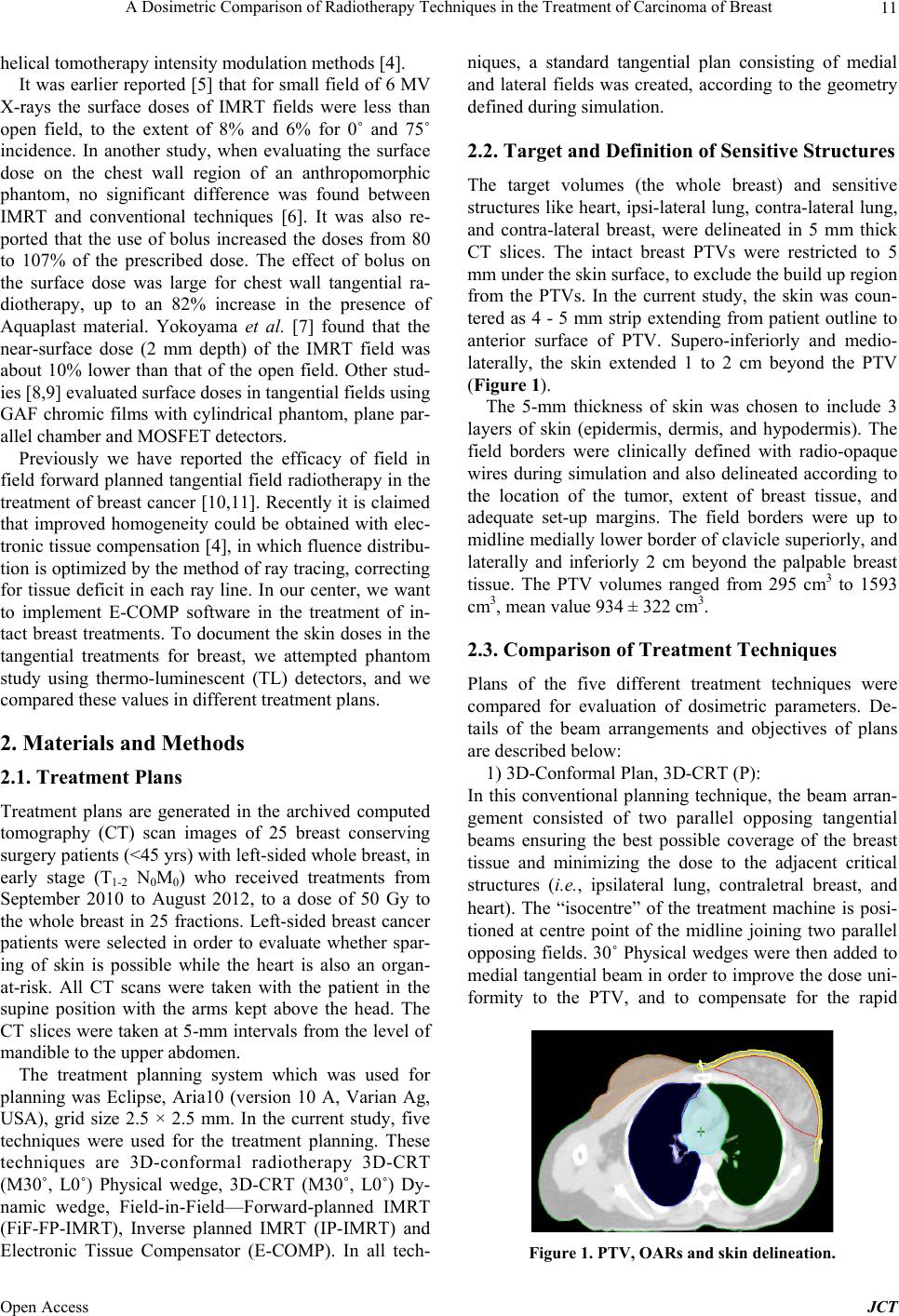 A Dosimetric Comparison of Radiotherapy Techniques in the Treatment of Carcinoma of Breast 11 helical tomotherapy intensity modulation methods [4]. It was earlier reported [5] that for small field of 6 MV X-rays the surface doses of IMRT fields were less than open field, to the extent of 8% and 6% for 0˚ and 75˚ incidence. In another study, when evaluating the surface dose on the chest wall region of an anthropomorphic phantom, no significant difference was found between IMRT and conventional techniques [6]. It was also re- ported that the use of bolus increased the doses from 80 to 107% of the prescribed dose. The effect of bolus on the surface dose was large for chest wall tangential ra- diotherapy, up to an 82% increase in the presence of Aquaplast material. Yokoyama et al. [7] found that the near-surface dose (2 mm depth) of the IMRT field was about 10% lower than that of the open field. Other stud- ies [8,9] evaluated surface doses in tangential fields using GAF chromic films with cylindrical phantom, plane par- allel chamber and MOSFET detectors. Previously we have reported the efficacy of field in field forward planned tangential field radiotherapy in the treatment of breast cancer [10,11]. Recently it is claimed that improved homogeneity could be obtained with elec- tronic tissue compensation [4], in which fluence distribu- tion is optimized by the method of ray tracing, correcting for tissue deficit in each ray line. In our center, we want to implement E-COMP software in the treatment of in- tact breast treatments. To document the skin doses in the tangential treatments for breast, we attempted phantom study using thermo-luminescent (TL) detectors, and we compared these values in different treatment plans. 2. Materials and Methods 2.1. Treatment Plans Treatment plans are generated in the archived computed tomography (CT) scan images of 25 breast conserving surgery patients (<45 yrs) with left-sided whole breast, in early stage (T1-2 N 0M0) who received treatments from September 2010 to August 2012, to a dose of 50 Gy to the whole breast in 25 fractions. Left-sided breast cancer patients were selected in order to evaluate whether spar- ing of skin is possible while the heart is also an organ- at-risk. All CT scans were taken with the patient in the supine position with the arms kept above the head. The CT slices were taken at 5-mm intervals from the level of mandible to the upper abdomen. The treatment planning system which was used for planning was Eclipse, Aria10 (version 10 A, Varian Ag, USA), grid size 2.5 × 2.5 mm. In the current study, five techniques were used for the treatment planning. These techniques are 3D-conformal radiotherapy 3D-CRT (M30˚, L0˚) Physical wedge, 3D-CRT (M30˚, L0˚) Dy- namic wedge, Field-in-Field—Forward-planned IMRT (FiF-FP-IMRT), Inverse planned IMRT (IP-IMRT) and Electronic Tissue Compensator (E-COMP). In all tech- niques, a standard tangential plan consisting of medial and lateral fields was created, according to the geometry defined during simulation. 2.2. Target and Definition of Sensitive Structures The target volumes (the whole breast) and sensitive structures like heart, ipsi-lateral lung, contra-lateral lung, and contra-lateral breast, were delineated in 5 mm thick CT slices. The intact breast PTVs were restricted to 5 mm under the skin surface, to exclude the build up region from the PTVs. In the current study, the skin was coun- tered as 4 - 5 mm strip extending from patient outline to anterior surface of PTV. Supero-inferiorly and medio- laterally, the skin extended 1 to 2 cm beyond the PTV (Figure 1). The 5-mm thickness of skin was chosen to include 3 layers of skin (epidermis, dermis, and hypodermis). The field borders were clinically defined with radio-opaque wires during simulation and also delineated according to the location of the tumor, extent of breast tissue, and adequate set-up margins. The field borders were up to midline medially lower border of clavicle superiorly, and laterally and inferiorly 2 cm beyond the palpable breast tissue. The PTV volumes ranged from 295 cm3 to 1593 cm3, mean value 934 ± 322 cm3. 2.3. Comparison of Treatment Techniques Plans of the five different treatment techniques were compared for evaluation of dosimetric parameters. De- tails of the beam arrangements and objectives of plans are described below: 1) 3D-Conformal Plan, 3D-CRT (P): In this conventional planning technique, the beam arran- gement consisted of two parallel opposing tangential beams ensuring the best possible coverage of the breast tissue and minimizing the dose to the adjacent critical structures (i.e., ipsilateral lung, contraletral breast, and heart). The “isocentre” of the treatment machine is posi- tioned at centre point of the midline joining two parallel opposing fields. 30˚ Physical wedges were then added to medial tangential beam in order to improve the dose uni- formity to the PTV, and to compensate for the rapid Figure 1. PTV, OARs and skin delineation. Open Access JCT 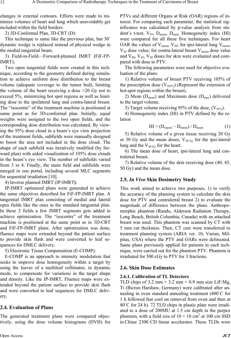 A Dosimetric Comparison of Radiotherapy Techniques in the Treatment of Carcinoma of Breast 12 changes in external contours. Efforts were made to mi- nimize volumes of heart and lung which unavoidably get included within the field borders. 2) 3D-Conformal Plan, 3D-CRT (D): This technique is same like the previous plan, but 30˚ dynamic wedge is replaced instead of physical wedge in the medial tangential beam. 3) Field-in-Field—Forward-planned IMRT (FiF-FP- IMRT): Two open tangential fields were created in this tech- nique, according to the geometry defined during simula- tion to achieve uniform dose distribution to the breast volume (adequate coverage to the tumor bed), limiting the volume of the heart receiving a dose >20 Gy not to exceed 5%, minimizing hot spot regions as well as limit- ing dose to the ipsilateral lung and contra-lateral breast. The “isocentre” of the treatment machine is positioned at same point as for 3D-conformal plan. Initially, equal weights were assigned to the two open fields, and the corresponding dose distribution was calculated. By view- ing the 95% dose cloud in a beam’s eye view projection of the treatment fields, subfields were manually designed to boost the area not included in the dose cloud. The shape of each subfield was iteratively modified (by for- ward plan) with aided visualization of 105% dose clouds in the beam’s eye view. The number of subfields varied from 3 to 4. Finally, the main field and subfields were merged in one portal, including several MLC segments for sequential irradiation [10]. 4) Inverse planned IMRT (IP-IMRT): IP-IMRT optimized plans were generated to achieve the same objectives described for FiF-FP-IMRT plan. A tangential IMRT plan consisting of medial and lateral open fields like the ones in the standard tangential plan. In these 2 fields a few IMRT segments gets added to achieve optimization. The “isocentre” of the treatment machine is positioned at the same point as in 3D-CRT and FiF-FP-IMRT plans. After optimization was done, fluence maps were extended beyond the patient surface to provide skin flash and were converted to leaf se- quences for DMLC delivery. 5) Electronic Tissue Compensation (E-COMP): E-COMP is an approach to intensity modulation that seeks to improve dose homogeneity within a target by using the leaves of a multileaf collimator, in dynamic mode, to compensate for variations in the target shape and density. Like the IP-IMRT, Fluence maps were ex- tended beyond the patient surface to provide skin flash and were converted to leaf sequences for DMLC deliv- ery. 2.4. Evaluation of Plans The generated treatment plans were compared objec- tively, using the dose volume histograms (DVH) for PTVs and different Organs at Risk (OAR) regions of in- terest. For comparing each parameter, the statistical sig- nificance was calculated by p-value analysis from stu- dent’s t-test. V95, Dmean, Dmax, Homogeneity index (HI) were compared for all these five techniques. For heart OAR the values of Vmean, V30; for ipsi-lateral lung Vmean, V20 dose value; for contra-lateral breast Vmean, dose value and V40, V45, V50 doses for skin were evaluated and com- pared with dose to PTV. The following parameters were used for objective eva- luation of the plans: 1) Relative volume of breast PTV receiving 105% of the prescription dose (V105%) (Represent the extension of hot-spot regions within the breast). 2) Mean (Dmean) and Maximum dose (Dmax) delivered to the target volume. 3) Target volume receiving 95% of the dose, (V95%). 4) Homogeneity index (HI) in PTV defined by the re- lation HI = (Dmaxm − Dminm) / Dmean (1) 5) Relative volume of a given tissue receiving 20 Gy or 30 Gy and the mean doses, V20 Gy for the ipsi-lateral lung and the V30 Gy for the heart. 6) The mean dose of heart, ipsi-lateral lung and con- traletral breast. 7) Relative volume of the skin receiving dose (40, 45, 50 Gy) and the mean dose. 2.5. In Vivo Skin Dosimetry Study This work aimed to achieve two purposes, 1) to verify the accuracy of the planning system to calculate the skin dose for PTV and contraletral breast 2) to evaluate the magnitude of difference between the plans. Anthropo- morphic phantom (Rando, Alderson Radiation Therapy, Long Beach, British Columbia, Canada) with an attached breast was used. This phantom was scanned by CT with 5 mm cut thickness. Then, CT cuts were transferred to treatment planning system (ARIA ver. 10, Varian, Mil- pitas, USA) where the PTV and OARs were delineated. Same plans previously applied for patients in each tech- nique, were carried out for the phantom PTV. Phantom is irradiated for 500 cGy to PTV for 3 fractions. 2.6. Skin Dose Estimates 2.6.1. Calibration of TL Detectors TLD chips of 3.2 mm × 3.2 mm × 0.9 mm size LiF:Mg, Ti (Bicron Harshaw, Germany) were calibrated after an- nealing in oven standard annealing treatment (400˚C for 1 h followed fast cool on removal from oven and then at 80˚C for 24 h). 72 TLD chips in plastic plate were irradi- ated to a dose of 200MU at 1.5 cm depth in the perpex phantom, with a field size of 10 × 10 cm2 at 100 cm SSD in Clinac 2300 CD linear accelerator. These TLDs were Open Access JCT 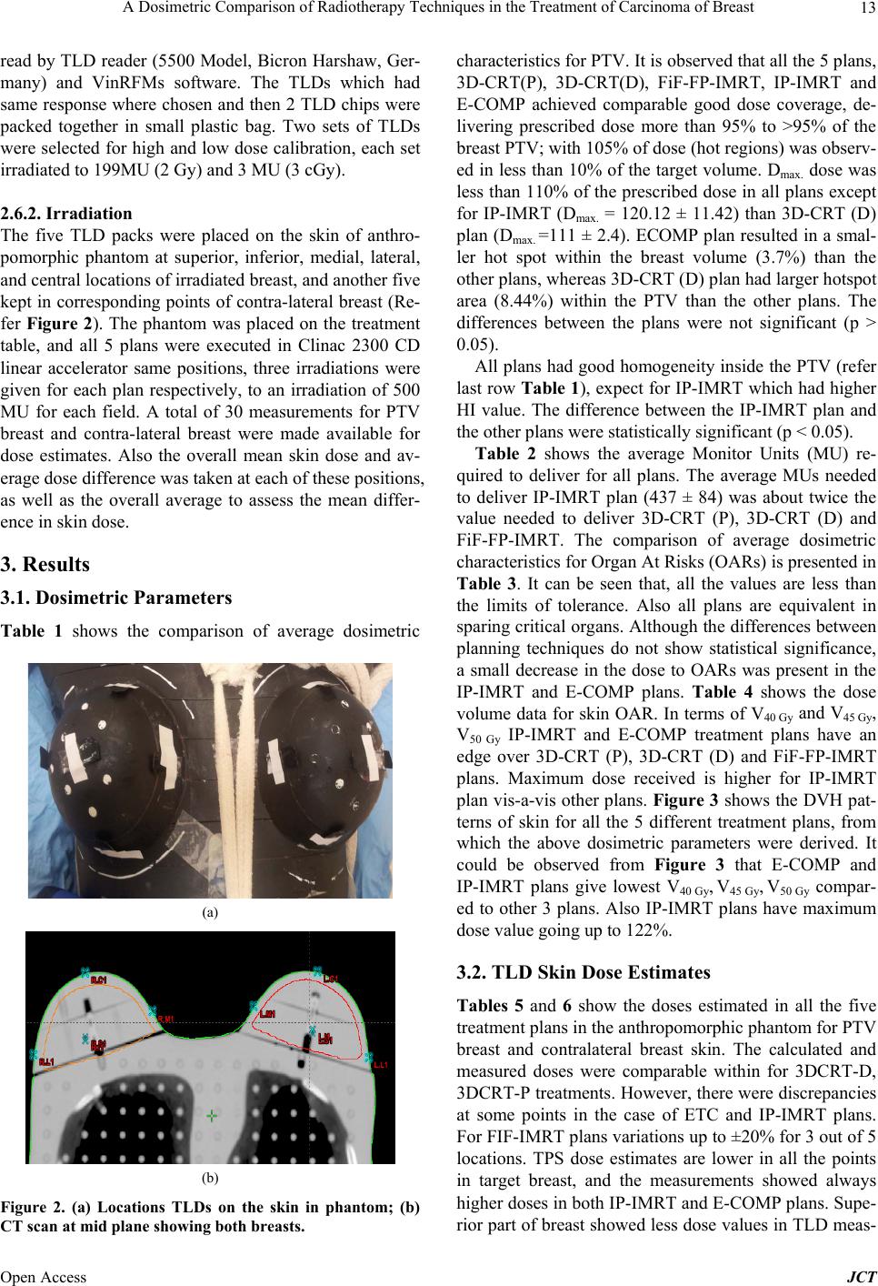 A Dosimetric Comparison of Radiotherapy Techniques in the Treatment of Carcinoma of Breast 13 read by TLD reader (5500 Model, Bicron Harshaw, Ger- many) and VinRFMs software. The TLDs which had same response where chosen and then 2 TLD chips were packed together in small plastic bag. Two sets of TLDs were selected for high and low dose calibration, each set irradiated to 199MU (2 Gy) and 3 MU (3 cGy). 2.6.2. Irradiation The five TLD packs were placed on the skin of anthro- pomorphic phantom at superior, inferior, medial, lateral, and central locations of irradiated breast, and another five kept in corresponding points of contra-lateral breast (Re- fer Figure 2). The phantom was placed on the treatment table, and all 5 plans were executed in Clinac 2300 CD linear accelerator same positions, three irradiations were given for each plan respectively, to an irradiation of 500 MU for each field. A total of 30 measurements for PTV breast and contra-lateral breast were made available for dose estimates. Also the overall mean skin dose and av- erage dose difference was taken at each of these positions, as well as the overall average to assess the mean differ- ence in skin dose. 3. Results 3.1. Dosimetric Parameters Table 1 shows the comparison of average dosimetric (a) (b) Figure 2. (a) Locations TLDs on the skin in phantom; (b) CT scan at mid plane showing both breasts. characteristics for PTV. It is observed that all the 5 plans, 3D-CRT(P), 3D-CRT(D), FiF-FP-IMRT, IP-IMRT and E-COMP achieved comparable good dose coverage, de- livering prescribed dose more than 95% to >95% of the breast PTV; with 105% of dose (hot regions) was observ- ed in less than 10% of the target volume. Dmax. dose was less than 110% of the prescribed dose in all plans except for IP-IMRT (Dmax. = 120.12 ± 11.42) than 3D-CRT (D) plan (Dmax. =111 ± 2.4). ECOMP plan resulted in a smal- ler hot spot within the breast volume (3.7%) than the other plans, whereas 3D-CRT (D) plan had larger hotspot area (8.44%) within the PTV than the other plans. The differences between the plans were not significant (p > 0.05). All plans had good homogeneity inside the PTV (refer last row Table 1 ), expect for IP-IMRT which had higher HI value. The difference between the IP-IMRT plan and the other plans were statistically significant (p < 0.05). Table 2 shows the average Monitor Units (MU) re- quired to deliver for all plans. The average MUs needed to deliver IP-IMRT plan (437 ± 84) was about twice the value needed to deliver 3D-CRT (P), 3D-CRT (D) and FiF-FP-IMRT. The comparison of average dosimetric characteristics for Organ At Risks (OARs) is presented in Table 3. It can be seen that, all the values are less than the limits of tolerance. Also all plans are equivalent in sparing critical organs. Although the differences between planning techniques do not show statistical significance, a small decrease in the dose to OARs was present in the IP-IMRT and E-COMP plans. Table 4 shows the dose volume data for skin OAR. In terms of V40 Gy and V45 Gy, V50 Gy IP-IMRT and E-COMP treatment plans have an edge over 3D-CRT (P), 3D-CRT (D) and FiF-FP-IMRT plans. Maximum dose received is higher for IP-IMRT plan vis-a-vis other plans. Figure 3 shows the DVH pat- terns of skin for all the 5 different treatment plans, from which the above dosimetric parameters were derived. It could be observed from Figure 3 that E-COMP and IP-IMRT plans give lowest V40 Gy, V45 Gy, V50 Gy compar- ed to other 3 plans. Also IP-IMRT plans have maximum dose value going up to 122%. 3.2. TLD Skin Dose Estimates Tables 5 and 6 show the doses estimated in all the five treatment plans in the anthropomorphic phantom for PTV breast and contralateral breast skin. The calculated and measured doses were comparable within for 3DCRT-D, 3DCRT-P treatments. However, there were discrepancies at some points in the case of ETC and IP-IMRT plans. For FIF-IMRT plans variations up to ±20% for 3 out of 5 locations. TPS dose estimates are lower in all the points in target breast, and the measurements showed always higher doses in both IP-IMRT and E-COMP plans. Supe- rior part of breast showed less dose values in TLD meas- Open Access JCT 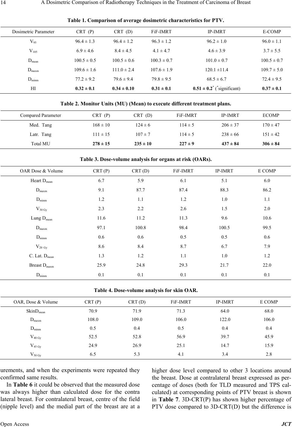 A Dosimetric Comparison of Radiotherapy Techniques in the Treatment of Carcinoma of Breast Open Access JCT 14 Table 1. Comparison of average dosimetric characteristics for PTV. Dosimetric Parameter CRT (P) CRT (D) FiF-IMRT IP-IMRT E-COMP V95 96.4 ± 1.3 96.4 ± 1.2 96.3 ± 1.2 96.2 ± 1.0 96.0 ± 1.1 V105 6.9 ± 4.6 8.4 ± 4.5 4.1 ± 4.7 4.6 ± 3.9 3.7 ± 5.5 Dmean 100.5 ± 0.5 100.5 ± 0.6 100.3 ± 0.7 101.0 ± 0.7 100.5 ± 0.7 Dmaxm 109.6 ± 1.6 111.0 ± 2.4 107.6 ± 1.9 120.1 ±11.4 109.7 ± 5.0 Dminm 77.2 ± 9.2 79.6 ± 9.4 79.8 ± 9.5 68.5 ± 6.7 72.4 ± 9.5 HI 0.32 ± 0.1 0.34 ± 0.10 0.31 ± 0.1 0.51 ± 0.2* (*significant) 0.37 ± 0.1 Table 2. Monitor Units (MU) (Mean) to execute different treatment plans. Compared Parameter CRT (P) CRT (D) FiF-IMRT IP-IMRT ECOMP Med. Tang 168 ± 10 124 ± 6 114 ± 5 206 ± 37 170 ± 47 Latr. Tang 111 ± 15 107 ± 7 114 ± 5 238 ± 66 151 ± 42 Total MU 278 ± 15 235 ± 10 227 ± 9 437 ± 84 306 ± 84 Table 3. Dose-volume analysis for organs at risk (OARs). OAR Dose & Volume CRT (P) CRT (D) FiF-IMRT IP-IMRT E COMP Heart Dmean 6.7 5.9 6.1 5.1 6.0 Dmaxm 9.1 87.7 87.4 88.3 86.2 Dminm 1.2 1.1 1.2 1.0 1.1 V30 Gy 2.3 2.2 2.6 1.5 2.0 Lung Dmean 11.6 11.2 11.3 9.6 10.6 Dmaxm 97.1 100.8 98.4 100.5 99.5 Dminm 0.6 0.6 0.5 0.5 0.6 V20 Gy 8.6 8.4 8.7 6.7 7.9 C. Lat. Dmean 1.3 1.2 1.1 1.0 1.2 Breast Dmaxm 25.9 24.8 29.3 21.7 22.0 Dminm 0.1 0.1 0.1 0.1 0.1 Table 4. Dose-volume analysis for skin OAR. OAR, Dose & Volume CRT (P) CRT (D) FiF-IMRT IP-IMRT E COMP SkinDmean 70.9 71.9 71.3 64.0 68.0 Dmaxm 108.0 109.0 106.0 122.0 106.0 Dminm 0.5 0.4 0.5 0.4 0.4 V40 Gy 52.5 52.8 56.9 39.7 45.9 V45 Gy 24.9 26.9 25.1 14.7 15.9 V50 Gy 6.5 5.3 4.1 3.4 2.8 urements, and when the experiments were repeated they confirmed same results. In Table 6 it could be observed that the measured dose was always higher than calculated dose for the contra lateral breast. For contralateral breast, centre of the field (nipple level) and the medial part of the breast are at a higher dose level compared to other 3 locations around the breast. Dose at contralateral breast expressed as per- centage of doses (both for TLD measured and TPS cal- culated) at corresponding points of PTV breast is shown in Table 7. 3D-CRT(P) has shown higher percentage of PTV dose compared to 3D-CRT(D) but the difference is 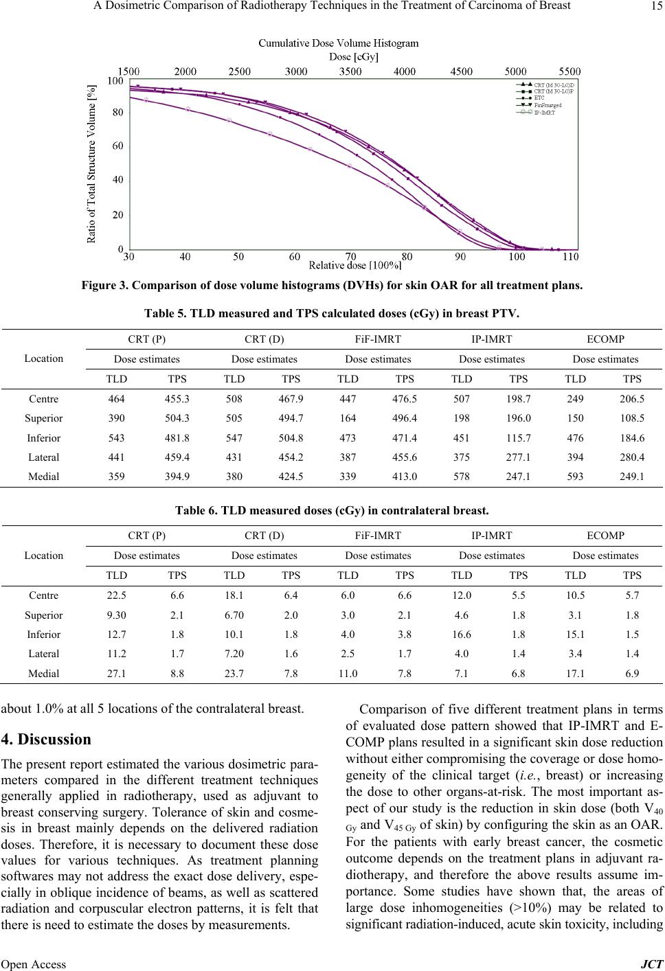 A Dosimetric Comparison of Radiotherapy Techniques in the Treatment of Carcinoma of Breast 15 Figure 3. Comparison of dose volume histograms (DVHs) for skin OAR for all treatment plans. Table 5. TLD measured and TPS calculated doses (cGy ) in brea st P TV. CRT (P) CRT (D) FiF-IMRT IP-IMRT ECOMP Dose estimates Dose estimates Dose estimates Dose estimates Dose estimates Location TLD TPS TLD TPS TLD TPS TLD TPS TLD TPS Centre 464 455.3 508 467.9 447 476.5 507 198.7 249 206.5 Superior 390 504.3 505 494.7 164 496.4 198 196.0 150 108.5 Inferior 543 481.8 547 504.8 473 471.4 451 115.7 476 184.6 Lateral 441 459.4 431 454.2 387 455.6 375 277.1 394 280.4 Medial 359 394.9 380 424.5 339 413.0 578 247.1 593 249.1 Table 6. TLD measured doses (cGy) in contralateral breast. CRT (P) CRT (D) FiF-IMRT IP-IMRT ECOMP Dose estimates Dose estimates Dose estimates Dose estimates Dose estimates Location TLD TPS TLD TPS TLD TPS TLD TPS TLD TPS Centre 22.5 6.6 18.1 6.4 6.0 6.6 12.0 5.5 10.5 5.7 Superior 9.30 2.1 6.70 2.0 3.0 2.1 4.6 1.8 3.1 1.8 Inferior 12.7 1.8 10.1 1.8 4.0 3.8 16.6 1.8 15.1 1.5 Lateral 11.2 1.7 7.20 1.6 2.5 1.7 4.0 1.4 3.4 1.4 Medial 27.1 8.8 23.7 7.8 11.0 7.8 7.1 6.8 17.1 6.9 about 1.0% at all 5 locations of the contralateral breast. 4. Discussion The present report estimated the various dosimetric para- meters compared in the different treatment techniques generally applied in radiotherapy, used as adjuvant to breast conserving surgery. Tolerance of skin and cosme- sis in breast mainly depends on the delivered radiation doses. Therefore, it is necessary to document these dose values for various techniques. As treatment planning softwares may not address the exact dose delivery, espe- cially in oblique incidence of beams, as well as scattered radiation and corpuscular electron patterns, it is felt that there is need to estimate the doses by measurements. Comparison of five different treatment plans in terms of evaluated dose pattern showed that IP-IMRT and E- COMP plans resulted in a significant skin dose reduction without either compromising the coverage or dose homo- geneity of the clinical target (i.e., breast) or increasing the dose to other organs-at-risk. The most important as- pect of our study is the reduction in skin dose (both V40 Gy and V45 Gy of skin) by configuring the skin as an OAR. For the patients with early breast cancer, the cosmetic outcome depends on the treatment plans in adjuvant ra- diotherapy, and therefore the above results assume im- portance. Some studies have shown that, the areas of large dose inhomogeneities (>10%) may be related to significant radiation-induced, acute skin toxicity, including Open Access JCT 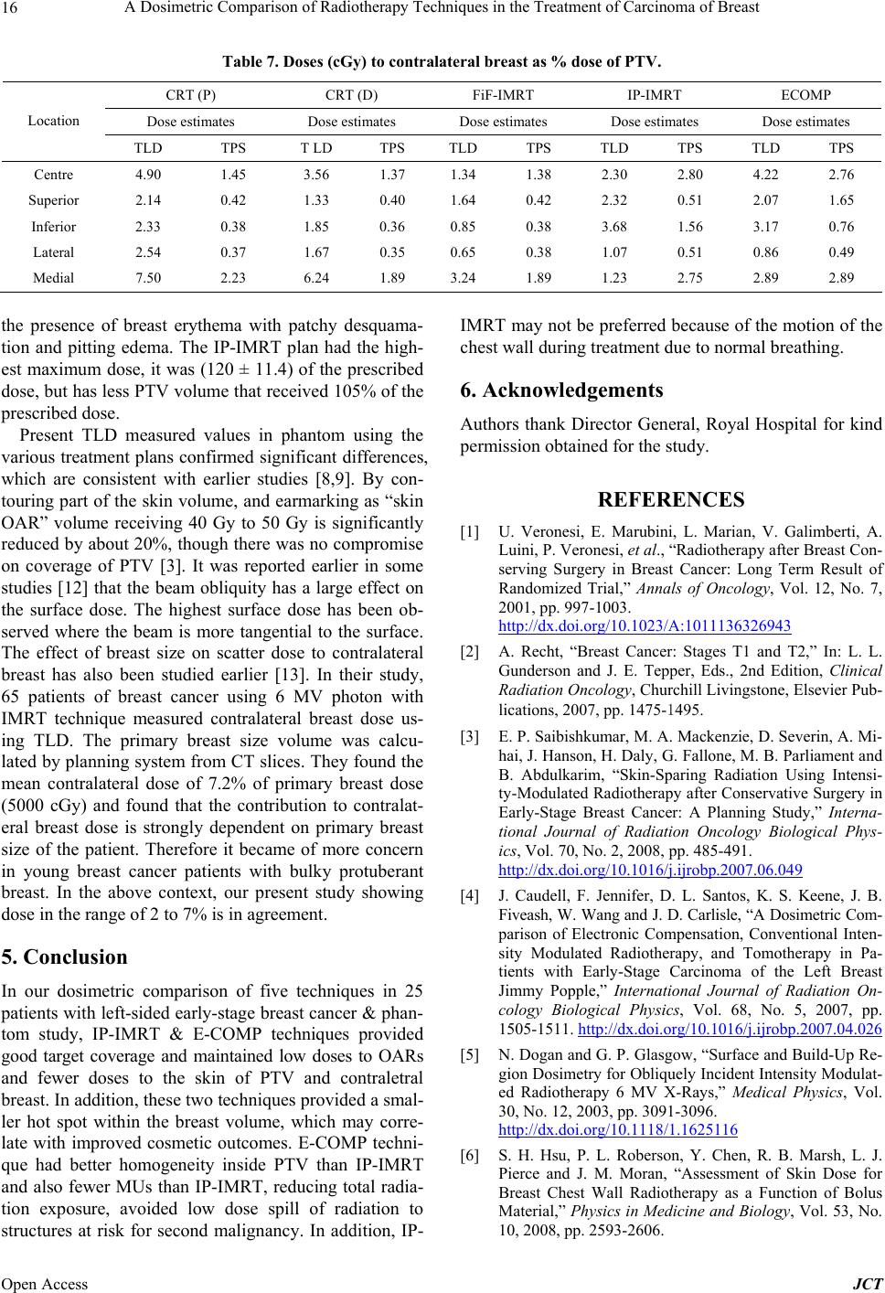 A Dosimetric Comparison of Radiotherapy Techniques in the Treatment of Carcinoma of Breast 16 Table 7. Doses (cGy) to contralateral breast as % dose of PTV. CRT (P) CRT (D) FiF-IMRT IP-IMRT ECOMP Dose estimates Dose estimates Dose estimates Dose estimates Dose estimates Location TLD TPS T LD TPS TLD TPS TLD TPS TLD TPS Centre 4.90 1.45 3.56 1.37 1.34 1.38 2.30 2.80 4.22 2.76 Superior 2.14 0.42 1.33 0.40 1.64 0.42 2.32 0.51 2.07 1.65 Inferior 2.33 0.38 1.85 0.36 0.85 0.38 3.68 1.56 3.17 0.76 Lateral 2.54 0.37 1.67 0.35 0.65 0.38 1.07 0.51 0.86 0.49 Medial 7.50 2.23 6.24 1.89 3.24 1.89 1.23 2.75 2.89 2.89 the presence of breast erythema with patchy desquama- tion and pitting edema. The IP-IMRT plan had the high- est maximum dose, it was (120 ± 11.4) of the prescribed dose, but has less PTV volume that received 105% of the prescribed dose. Present TLD measured values in phantom using the various treatment plans confirmed significant differences, which are consistent with earlier studies [8,9]. By con- touring part of the skin volume, and earmarking as “skin OAR” volume receiving 40 Gy to 50 Gy is significantly reduced by about 20%, though there was no compromise on coverage of PTV [3]. It was reported earlier in some studies [12] that the beam obliquity has a large effect on the surface dose. The highest surface dose has been ob- served where the beam is more tangential to the surface. The effect of breast size on scatter dose to contralateral breast has also been studied earlier [13]. In their study, 65 patients of breast cancer using 6 MV photon with IMRT technique measured contralateral breast dose us- ing TLD. The primary breast size volume was calcu- lated by planning system from CT slices. They found the mean contralateral dose of 7.2% of primary breast dose (5000 cGy) and found that the contribution to contralat- eral breast dose is strongly dependent on primary breast size of the patient. Therefore it became of more concern in young breast cancer patients with bulky protuberant breast. In the above context, our present study showing dose in the range of 2 to 7% is in agreement. 5. Conclusion In our dosimetric comparison of five techniques in 25 patients with left-sided early-stage breast cancer & phan- tom study, IP-IMRT & E-COMP techniques provided good target coverage and maintained low doses to OARs and fewer doses to the skin of PTV and contraletral breast. In addition, these two techniques provided a smal- ler hot spot within the breast volume, which may corre- late with improved cosmetic outcomes. E-COMP techni- que had better homogeneity inside PTV than IP-IMRT and also fewer MUs than IP-IMRT, reducing total radia- tion exposure, avoided low dose spill of radiation to structures at risk for second malignancy. In addition, IP- IMRT may not be preferred because of the motion of the chest wall during treatment due to normal breathing. 6. Acknowledgements Authors thank Director General, Royal Hospital for kind permission obtained for the study. REFERENCES [1] U. Veronesi, E. Marubini, L. Marian, V. Galimberti, A. Luini, P. Veronesi, et al., “Radiotherapy after Breast Con- serving Surgery in Breast Cancer: Long Term Result of Randomized Trial,” Annals of Oncology, Vol. 12, No. 7, 2001, pp. 997-1003. http://dx.doi.org/10.1023/A:1011136326943 [2] A. Recht, “Breast Cancer: Stages T1 and T2,” In: L. L. Gunderson and J. E. Tepper, Eds., 2nd Edition, Clinical Radiation Oncology, Churchill Livingstone, Elsevier Pub- lications, 2007, pp. 1475-1495. [3] E. P. Saibishkumar, M. A. Mackenzie, D. Severin, A. Mi- hai, J. Hanson, H. Daly, G. Fallone, M. B. Parliament and B. Abdulkarim, “Skin-Sparing Radiation Using Intensi- ty-Modulated Radiotherapy after Conservative Surgery in Early-Stage Breast Cancer: A Planning Study,” Interna- tional Journal of Radiation Oncology Biological Phys- ics, Vol. 70, No. 2, 2008, pp. 485-491. http://dx.doi.org/10.1016/j.ijrobp.2007.06.049 [4] J. Caudell, F. Jennifer, D. L. Santos, K. S. Keene, J. B. Fiveash, W. Wang and J. D. Carlisle, “A Dosimetric Com- parison of Electronic Compensation, Conventional Inten- sity Modulated Radiotherapy, and Tomotherapy in Pa- tients with Early-Stage Carcinoma of the Left Breast Jimmy Popple,” International Journal of Radiation On- cology Biological Physics, Vol. 68, No. 5, 2007, pp. 1505-1511. http://dx.doi.org/10.1016/j.ijrobp.2007.04.026 [5] N. Dogan and G. P. Glasgow, “Surface and Build-Up Re- gion Dosimetry for Obliquely Incident Intensity Modulat- ed Radiotherapy 6 MV X-Rays,” Medical Physics, Vol. 30, No. 12, 2003, pp. 3091-3096. http://dx.doi.org/10.1118/1.1625116 [6] S. H. Hsu, P. L. Roberson, Y. Chen, R. B. Marsh, L. J. Pierce and J. M. Moran, “Assessment of Skin Dose for Breast Chest Wall Radiotherapy as a Function of Bolus Material,” Physics in M edicine and B iology, Vol. 53, No. 10, 2008, pp. 2593-2606. Open Access JCT  A Dosimetric Comparison of Radiotherapy Techniques in the Treatment of Carcinoma of Breast 17 http://dx.doi.org/10.1088/0031-9155/53/10/010 [7] S. Yokoyama, P. L. Roberson, D. W. Litzenberg, J. M. Mo- ran and B. A. Fraass, “Surface Buildup Dose Dependence on Photon Field Delivery Technique for IMRT,” Journal of Applied Clinical Medical Physics, Vol. 5, No. 2, 2004, pp. 71-81. http://dx.doi.org/10.1120/jacmp.2020.21706 [8] M. Nakano, R. F. Hill, M. Whitaker, J. H. Kim and Z. J. Kuncic, “A Study of Surface Dosimetry for Breast Cancer Radiotherapy Treatments Using Gafchromic EBT2 Film,” Journal of Applied Clinical Medical Physics, Vol. 13, No. 3, 2012, pp. 83-96. [9] K. Y. Quach, J. Morales, M. J. Butson, A. B. Rosenfeld and P. E. Metcalfe, “Measurement of Radiotherapy X-Ray Skin Dose on a Chest Wall Phantom,” Medical Physics, Vol. 27, No. 7, 2000, pp. 1676-1680. [10] K. Krishnamurthy, S. S. Sivakumar, C. A. Davis, R. Ra- vichandran and K. ElGhamrawy, “Optimization of Dose Distribution with Multi-Leaf Collimator Using Field-in- Field Technique for Parallel Opposing Tangential Beams of Breast Cancers,” Journal of Medical Physics, Vol. 33, No. 2, 2008, pp. 60-63. http://dx.doi.org/10.4103/0971-6203.41194 [11] Z. S. Al-Rahbi, Z. Al Mandhari, R. Ravichandran, F. Al-Kindi, C. A. Davis, S. Bhasi, N. Satyapal and B. Rajan, “Dosimetric Comparison of Intensity Modulated Radio- therapy Isocentric Field Plans and Field in Field forward Plans in the Treatment of Breast Cancer,” Journal of Me- dical Physics, Vol. 38, No. 1, 2013, pp. 34-41. http://dx.doi.org/10.4103/0971-6203.106601 [12] A. Kelly, N. Hardcastle, Metcalfe, D. Cutajar, A. Quinn, K. Foo, M. Cardoso, S. Barlin and A. Rosenfeld, “Surface Dosimetry for Breast Radiotherapy in the Presence of Immobilization Cast Material,” Physics in Medicine and Biology, Vol. 56, No. 4, 2011, pp. 1001-1013. http://dx.doi.org/10.1088/0031-9155/56/4/008 [13] A. K. Bhatnagar, D. E. Heron, M. Deutch, E. Brandner, W. U. Andrew and S. Kalnicki, “Does Breast Size Affect the Scatter Dose to Ipsilateral Lung, Heart or Contralat- eral Breast in Primary Irradiation Using Intensity Modu- lated Radiotherapy (IMRT),” American Journal of Clini- cal Oncology, Vol. 29, No. 1, 2006, pp. 80-84. http://dx.doi.org/10.1097/01.coc.0000198743.80991.15 Open Access JCT
|