Journal of Computer and Communications, 2013, 1, 62-66
Published Online December 2013 (http://www.scirp.org/journal/jcc)
http://dx.doi.org/10.4236/jcc.2013.17015
Open Access JCC
Study on Insertion Loss of Fiber Fabry-Per ot Filters
Sheng-Nan Su, Hai-Bing Qi, Yong-Lin Yu*
Wuhan National Laboratory for Optoelectronics, Huazhong University of Science and Technology, Wuhan, China.
Email: *yonglinyu@mail.hust.edu.cn
Received October 2013
ABSTRACT
Fiber Fabry-Perot (FFP) filters have been widely used in optical fiber communications, and insertion loss (IL) is one of
its important characteristics. Based on theoretically analysis, factors related to IL were discussed. In order to investigate
the IL of different structures, simulations are carried out with finite-difference time-domain (FDTD) algorithm. Com-
parisons are made between the optimized structur e and full-size-mirror FFP filter, and fiber-inserted FFP filter as well.
Simulation results demonstrated that the finite-size-mirror structure can confine the mode size of the open resonator,
hence reduce the IL of FFP filter.
Keywords: FFP Filter; Insertion Loss; Finesse
1. Introduction
Tunable fiber Fabry-Perot filters (FFP-TFs) are widely
used in optical fibe r communications and optical sensing
systems, since they have advantages of low loss, high
tuning speed, wide tuning range, high finesse, and flexi-
ble structures and different practical applications. For opt-
ical fiber communication applications, FFP-TFs can be
used to select wavelength for each channel in wavelength
division multiplexing (WDM) system [1]. In fiber Brag
grating (FB G) sensing systems, FFP-TFs can be adopted
in dynamically demodulation [2]. With the help of a
FFP-TF, wavelength tuning of an optical fiber ring laser
could be realized [3]. FFP-TFs also find applications in
clock signal extraction in all optical 3R regeneration sys-
tem and optical network unit [4,5]. Recently, applications
of FFP-TFs in microwave photonic system have drawn
some attentions [6,7].
Insertion loss is one of the important charac teristics of
FFP-TFs. Insertion loss is classified into two kinds of
loss, namely extrinsic loss and intrinsic loss. The extrin-
sic loss of FFP-TFs can be reduced by improvement of
device manufacturing process and assembling preicision.
Reducing the intrinsic loss of FFP-TFs, however, needs
to optimize their structures. For this purpose, a lot of
work has been reported. In1989, D. Marcuse from Bell
labs and MOI, USA, proposed a FFP-TF structure with a
inserted waveguide [8,9]. In 2005, Y. Bao et al. from
MOI, USA, patented a FFP-TF structure with a concave
cavity [10]; In 2011, Fujikawa et al. from Tokyo Univer-
sity, Japan, presented a structure with an expanded core
fiber [11]. In 2008, C. Tang et al. from Beijing Institute
of Technology put forward a structure with convex lens
after the mirrors [12]. In 2009, w e propo s ed a new struc-
ture based on finite design [13 ].
In this paper, we begin with fundamental analysis of
insertion loss of FFP-TFs, and discuss effects of key pa-
rameters of the structure on the insertion loss. Then we
focused on our new finite-size-mirror structure. Charac-
teristics and mode distribution of the finite-size-mirror
FFP-TF are studied and simulated. Finally we compare
this new finite-size-mirror structure with fiber inserted
structure and full-size-mirror structure.
2. Basic Principle
The FFP filter is based on multiple beam of F-P cavity.
As is shown in Figure 1(a), FFP filter which consists of
two aligned fiber coating with high reflecting film. As-
suming that the light enters the F-P cavity with an angle
(θ) against the normal, the light beams exit the second
fiber parallelly after multiple reflecting, as is shown in
Figure 1(b). The parallel beams are amplitude decreased
and superposed coherent.
The intensity (
( )
t
I
) of the output light is,
(1)
( )
i
I
is the intensity of input light,
m
R
is the reflectiv-
ity of the coated film,
m
T
is the transmission of the
mirror. is the phase difference of the
*Corresponding a uthor.
Study on Insertion Loss of Fiber Fabry-Perot Filters
Open Access JCC
63
mirrors
face of 1
st
fiberface of 2
nd
fiber
(a) The structure of a FFP filter
face of 1
st
fiberface of 2
nd
fiber
n
Rm Tm d
(b) The principle of FFP filter
Figure 1. The structure of FFP filter (a) and the principle of
FFP filter (b).
adjacent parallel beams, n is the refractive index of the
medium within the F-P cavity, d is the length of the F-P
cavity and λ is the central wavelength of the input light.
The wavelength which meets
will exit FFP filter. Obviously,
tuning the transmission wavelength can be achieved by
changing the parameters related to the phase difference.
The transmittance of the FFP filter, is defined as the ratio
of
( )
t
I
to
( )
i
I
, that is,
(2 )
When phase difference
δ= 2mπ
, FFP filter attains
maximum transmittance , namely peak transmittance (
).
Insertion loss (IL) of a FFP filter is then expressed as,
( )()
( )
( )
it
max
i
I -I
IL= -10lg= -10lgT.
I




(3 )
The finesse (F) of FFP filter is, ,
despite of loss (L). When considering loss, the peak
transmittance is [14],
( )
2
m
T =11+LT.
(4)
If the loss is ultra small, the finesse is then expressed
as follow,
(5)
From the above analysis, it is obviously that low IL is
necessary if high peak transmittance and high finesse is
required.
Factors leading to insertion loss of FFP filter can be
classified into two kinds, extrinsic loss and intrinsic loss,
according to the method to classify the splice loss of sin-
gle mode fiber [ 1 6]. Extrinsic loss is generated during the
manufacturing process, including loss dues to fiber tilt
and offset. Intrinsic loss is caused by the structure of FFP
filter. It includes diffraction loss and mode mismatch loss
between guided wave mode and open mode of F-P cavity.
Improvement of the device manufacturing and assembly
precision will reduce the extrinsic loss. However, reduc-
ing the intrinsic loss n eeds to optimize the structure of
FFP filter.
3. Fundamental Analysis on Insertion Loss
Transmittance coefficient (
f
T
) of single mode fiber with
longitudinal separation can be calculated with [17],
(6)
ω is the mode field radius two optical fibers respectively,
is the normalized fiber separation distance,
k is the free space wave number. Consider that the input
field bounce s back and forth in the FFP filter's resonator,
it traverses an effective length that is defined by the mir-
ror transmission [8],
m
L2d T.
E=
(7)
In a simple-minded view, we regard the transmittance
of FFP filter as a splice of identical fibers with an end
separation equal to the effective length. Supp ose,
(8)
then
2
2
x
T= .
1+x
(9)
This expression is plotted in Figure 2.
It is apparently that the peak transmittance increases
with the increasing of x. Equation (8) shows that ex-
panding the fiber mode field radius, increasing reflectiv-
Figure 2. The peak transmittance varies with x.
05 10 15 20 2530
0.5
0.6
0.7
0.8
0.9
1
x
T
Study on Insertion Loss of Fiber Fabry-Perot Filters
Open Access JCC
64
ity and shorten cavity length could enlarge x. Large
mode field radius will reduce the mode mismatching loss,
as a result, the peak transmittance increases. Improving
the transmittance of mirror or shorten the cavity length
will also increase peak transmittance of FFP filter, cause
the shorter the length is, the less diffraction loss there
will be. All these relationships are plotted in Figure 3.
4. Finite-Size-Mirror Structure
For the purpose of reduction of IL, we proposed a new
structure, named a Finite-size-mirror structure [13]. As is
shown in Figure 4, w e use a finite mirror substituting the
traditional mirror with a full-fiber-end covering mirror
substituting traditional mirror. In this new structure, mir-
rors only cover part of fiber ends. Mode size of open
resonator is proportion to its size [18], so smaller mode
size can be attained with short radius of mirror. None-
theless, short radius mirrors increase diffraction loss.
Finite-size-mirror structure can be worked on condition
that an optimal radius of mirror is found out.
Relation of transmittance with radii of mirrors of the
FFP-TF is investigated with the help of finite difference
time domain (FDTD) algorithm. The mirror reflectivity
is set as 0.697, and cavity length is set as 9 μm. As a re-
sult, relationship between peak transmittance and radius
of mirror is shown in Figure 5.
Figure 5 clearly shows that the peak transmittance of
FFP-TF firstly increases with the increasing radius of the
mirrors. However, it decreases when the radius of mir-
rors increase to a certain value (about 6 μm), and then it
tends to be a constant when the radius of mirrors further
increases (>12 μm). Figure 5 indicates that there is a
lowest value of the IL of FFP-TF, corresponding to the
maximum value of th e peak transmittance.
5. Simulations and Comparisons
We analyzed key parameters and output mode field and
compared finite-size-mirror structure with other two struc-
tures to study more about finite-size-mirror FFP-TF. Here,
three structures are investigated as shown in Figure 6.
Figure 6(a) shows typical structure with full size mirrors,
Figure 6(b) represents a fiber inserted structure, and Fig-
ure 6(c) is our structure with finite size mirrors. Simula-
tions for the above three structures are carried ou t in two
Figure 3. The peak transmittance of FFP filter varies with ω0, Tm and d.
mirrors
Figure 4. The structure of Finite-size-mirror FFP filter.
Figure 5. Peak transmittance varies with radii of mirrors.
(a) Full-size-mirror FFP filter
(b) Fiber inserted FFP filter
(c) Finite-size-mirror FFP filter
Figure 6. Structures of the three kinds of FFP filters.
020 40 60 80100
0
0.2
0.4
0.6
0.8
1T
m
=0.03,d=10µm
ω(µm)
T
010 20 30 40 50
0
0.2
0.4
0.6
0.8
1
d(µm)
T
T
m
=0.03,ω=5.7µm
00.2 0.4 0.6 0.81
0
0.2
0.4
0.6
0.8
1
T
m
T
ω=5.7µm,d=10µm
Study on Insertion Loss of Fiber Fabry-Perot Filters
Open Access JCC
65
dimension and three dimension. Transmission spectra can
be extracted from results of two dimension simulation.
Peak transmittance, free spectral range and finesse can be
found out from transmission spectrum. Results of three
dimension simulation can be used to analyze distribution
of output mode.
In the simulation, we assume that the radius of mirrors
is the same as that of the fiber cladding for Figure 6(a)
and Figure 6 (b), and the radius of mirror is 6 μm. For all
cases, the reflectivity is 0.697, the optical cavity’s optical
length is 9 μm and central wavelength is 1.495 μm. Si-
mulated transmission spectra of three FFP filter struc-
tures are shown in Figure 7. The key characteristics,
such as insertion loss and finesse, are listed in Table 1.
In Table 1, structures (a) (b) (c) correspond with three
structures cases shown in Figure 6 respectively. M.R.
means the radius of mirror, T represents peak transmit-
tance of a FFP filter, Tmin is the valley value of spec-
trum. FSR and FWHM are free spectral range, full width
at half maximum of spectrum separately. F and IL are
finesse and insertion loss of a filter, respectively. Clearly,
for Fig ures 6(b) and (c), there are some reduction of the
insertion loss due to improvements on structure.
More intuitive resu lts obtained by three-dimensional
simulation are shown in Figure 8, w hich present distri-
bution of output mode field. It can be seen that, for full-
(a) Full-size-mirror FFP filter
(b) Fiber inserted FFP filter
(c) Finite-size-mirror FFP filter
Figure 7. Simutlated transmission spectra of FFP filters.
Table 1. parameters of three different FFP filters.
structures (a) (b) (c)
M.R.(μm) 60 60 6
T 0.875 0.903 0.921
Tmin 0.0311 0.0553 0.0322
FSR(nm) 118 109 118
FWHM(nm) 20.4 18.0 14.7
F 6 6 8
IL/dB 0.580 0.443 0.357
(a)Full-size-mirror FFP filter
(b) Fiber inserted FFP filter
(c) Finite-size-mirror FFP filter
Figure 8. Mode field distribution of output field.
size-mirror structure and fiber inserted structure, the out-
put field of filters d istributes in the area of fiber cladding
and core, while for the finite-size-mirror filter the output
field concentrates in the area of fiber core, and its centre
intensity is much stronger. This is due to the reduction of
Study on Insertion Loss of Fiber Fabry-Perot Filters
Open Access JCC
66
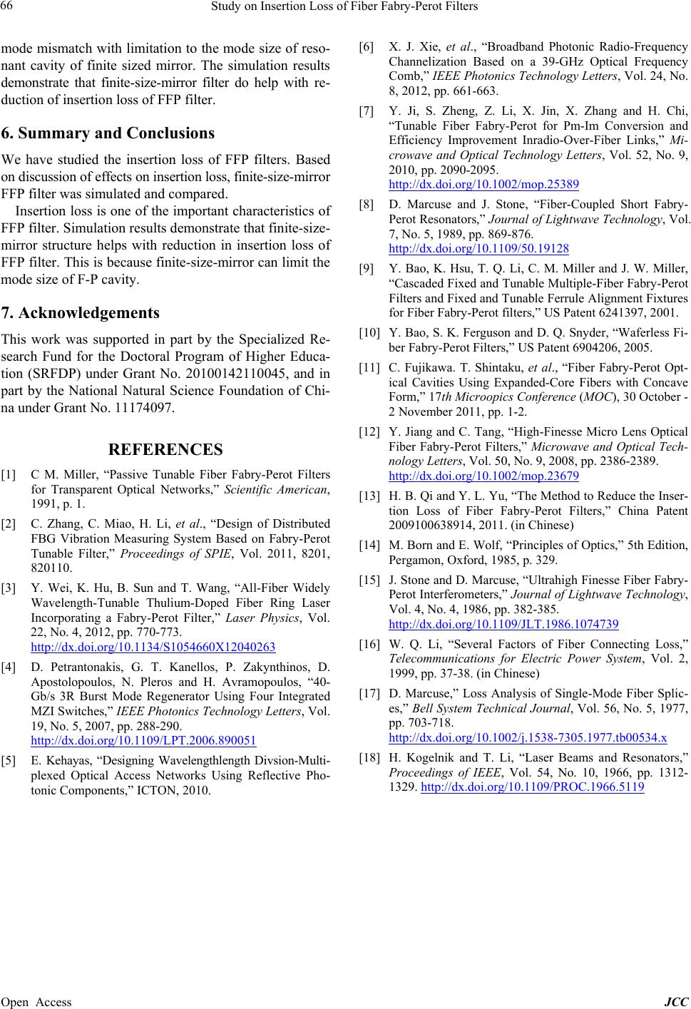
mode mis match with limitation to the mode size of reso-
nant cavity of finite sized mirror. The simulation results
demonstrate that finite-size-mirror filter do help with re-
duction of insertion loss of FFP filter.
6. Summary and Conclusions
We have studied the insertion loss of FFP filters. Based
on discussion of effects on insertion loss, finite-size-mirror
FFP filter was simulated a nd compared.
Insertion loss is one of the important charac teristics of
FFP filter. Simulation results demonstrate that finite-size-
mirror structure helps with reduction in insertion loss of
FFP filter. This is because finite-size-mirror can limit the
mode size of F-P cavity.
7. Acknowledgements
This work was supporte d in part by the Specialized Re-
search Fund for the Doctoral Program of Higher Educa-
tion (SRFDP) under Grant No. 20100142110045 , and in
part by the National Natural Science Foundation of Chi-
na under Grant No. 11174097.
REFERENCES
[1] C M. Miller, “Passive Tunable Fiber Fabry-Perot Filters
for Transparent Optical Networks,” Scientific American,
1991, p. 1.
[2] C. Zhang, C. Miao, H. Li, et al., “Design of Distributed
FBG Vibration Measuring System Based on Fabry-Perot
Tunable Filter,” Proceedings of SPIE, Vol. 2011, 8201,
820110.
[3] Y. Wei, K. Hu, B. Sun and T. Wang, “All-Fiber Widely
Wavelength-Tunable Thulium-Doped Fiber Ring Laser
Incorporating a Fabry-Perot Filter,” Laser Physics, Vol.
22, No. 4, 2012, pp. 770-773.
http://dx.doi.org/10.1134/S1054660X12040263
[4] D. Petrantonakis, G. T. Kanellos, P. Zakynthinos, D.
Apostolopoulos, N. Pleros and H. Avramopoulos, “40-
Gb/s 3R Burst Mode Regenerator Using Four Integrated
MZI Switches,” IEEE Photonics Technology Letters, Vol.
19, No. 5, 2007, pp. 288-290.
http://dx.doi.org/10.1109/LPT.2006.890051
[5] E. Kehayas, “Designing Wavelengthlength Divsion-Multi-
plexed Optical Access Networks Using Reflective Pho-
tonic Components,” ICTON, 2010.
[6] X. J. Xie, et al., “Broadband Photonic Radio-Frequency
Channelization Based on a 39-GHz Optical Frequency
Comb,” IEEE Photonics Technology Letters, Vol. 24, No.
8, 2012, pp. 661-663.
[7] Y. Ji, S. Zheng, Z. Li, X. Jin, X. Zhang and H. Chi,
“Tunable Fiber Fabry-Perot for Pm-Im Conversion and
Efficiency Improvement Inradio-Over-Fiber Links,” Mi-
crowave and Optical Technology Letters, Vol. 52, No. 9,
2010, pp. 2090-2095.
http://dx.doi.org/10.1002/mop.25389
[8] D. Marcuse and J. Stone,Fiber-Coupled Short Fabry-
Perot Resonators,” Journal of Lightwave Technology, Vol.
7, No. 5, 1989, pp. 869-876.
http://dx.doi.org/10.1109/50.19128
[9] Y. Bao, K. Hsu, T. Q. Li, C. M. Miller and J. W. Miller,
Cascaded Fixed and Tunable Multiple-Fiber Fabr y-Perot
Filters and Fixed and Tunable Ferrule Alignment Fixtures
for Fiber Fabry-Perot filters,” US Patent 6241397, 2001.
[10] Y. Bao, S. K. Ferguson and D. Q. Snyder, “Waferless Fi-
ber Fabry-Perot Filters,” US Patent 6904206, 2005.
[11] C. Fujikawa. T. Shintaku, et al., “Fiber Fabry-Perot Opt-
ical Cavities Using Expanded-Core Fibers with Concave
Form,” 17th Microopics Conference (MOC), 30 October -
2 November 2011, pp. 1-2.
[12] Y. Jiang and C. Tang, “High-Fi nesse Micro Lens Optical
Fiber Fabry-Perot Filters,” Microwave and Optical Tech-
nology Letters, Vol. 50, No. 9, 2008, pp. 2386-2389.
http://dx.doi.org/10.1002/mop.23679
[13] H. B. Qi and Y. L. Yu, “The Method to Reduce the Inser-
tion Loss of Fiber Fabry-Perot Filters,” China P atent
2009100638914, 2011. (in Chinese)
[14] M. Born and E. Wolf, “Principles of Optics,” 5th Edition,
Pergamon, Oxford, 1985, p. 329.
[15] J. Stone and D. Marcuse , “Ultrahigh Finesse Fiber Fabry-
Perot Interferometers,” Journal of Lightwave Technology,
Vol. 4, No. 4, 1986, pp. 382-385.
http://dx.doi.org/10.1109/JLT.1986.1074739
[16] W. Q. Li, “Several Factors of Fiber Connecting Loss,”
Telecommunications for Electric Power System, Vol. 2,
1999, pp. 37-38. (in Chinese)
[17] D. Marcuse,” Loss Analysis of Single-Mode Fiber Splic-
es,” Bell System Technical Journal, Vol. 56, No. 5, 1977,
pp. 703-718.
http://dx.doi.org/10.1002/j.1538-7305.1977.tb00534.x
[18] H. Kogelnik and T. Li,Laser Beams and Resonators,”
Proceedings of IEEE, Vol. 54, No. 10, 1966, pp. 1312-
1329. http://dx.doi.org/10.1109/PROC.1966.5119