 Modern Mechanical Engineering, 2013, 3, 191-201 Published Online November 2013 (http://www.scirp.org/journal/mme) http://dx.doi.org/10.4236/mme.2013.34026 Open Access MME Analytical Solutions of Dynamic Crack Models of Bridging Fiber Pull-Out in Unidirectional Composite Materials Yuntao Wang1, Yunhong Cheng2, Nianchun Lü3, Jin Cheng4 1College of Mechanical Engineering, Liaoning Technical University, Fuxin, China 2Department of Civil Engineering, Northeastern University, Shenyang, China 3School of Material Science and Engineering, Shenyang Ligong University, Shenyang, China 4Department of Astronautics and Mechanics, Harbin Institute of Technology, Harbin, China Email: wyt234@163.com, cyh_neu@163.com, lnc_65@163.com, chengjin@ hit.edu.cn Received September 22, 2013; revised October 29, 2013; accepted November 15, 2013 Copyright © 2013 Yuntao Wang et al. This is an open access article distributed under the Creative Commons Attribution License, which permits unrestricted use, distribution, and reproduction in any medium, provided the original work is properly cited. ABSTRACT An elastic analysis of an internal central crack with bridging fibers parallel to the free surface in an infinite orthotropic anisotropic elastic plane was analyzed, and the crack extension should occur in the format of self-similarity. When the fiber strength is over its maximum tensile stress, the fiber breaks. By means of complex variable functions, the problem considered can be easily translated into Reimann-Hilbert mixed boundary value problem. Utilizing the built dynamic model of bridging fiber pull-out in unidirectional composite materials, analytical solutions of the displacements, stresses and stress intensity factors under the action of increasing loads Pt5/x5, Px5/t4 are obtained, respectively. After those ana- lytical solutions were used by superposition theorem, the solutions to arbitrary complex problems were acquired. Keywords: Composite Materials; Bridging Fibers; Analytical Solutions; Crack; Variable Loads 1. Introduction It is well known that the matrix cracking as well as frac- ture process of the bridging fibers is one of the signifi- cant mechanisms of the cracking expansion in fiberrein- forced composite materials, such as unidirectional fiber- reinforced brittle matrix composites [1,2], and threedi- mensional fiber-reinforced composites with an ortho- gonal fiber structure [3]. Literature [4] proposed an ap- proach for the assessment of the distribution of the trac- tion force for a crack with bridging fibers in an infinite, orthotropic elastic plane under a uniform remove tension stress. Most researchers, such as Woo, Lee and Tsai [5-7] etc, almost investigated static problems of composite ma- terials; moreover, they obtained only numerical solutions. Literature [8] set up a model of bridging fiber pull-out, but it also acquired the numerical solutions under the sta- tic conditions. It is indispensable to consider the mecha- nical analysis of matrix cracking with bridging fibers, so as to evaluate the distribution of the axis traction force in each fiber. However, the fractures of composite materials often arise in dynamic conditions, so accordingly it is ex- tremely important to research their fracture dynamics problems. In an orthotrpic medium, elastodynamics crack problems were studied and closed solutions were also gained, but bridging fiber pull-out problems weren’t dealt with in literatures [9,10]. Bridging fiber pull-out is very complicated and cockamamie in dynamic fracture process of composite materials, so a lot of difficulty must be overcome in studying dynamic crack expansion prob- lems on bridging fiber pull-out of composite materials. When composite materials occur in a crack, bridging fiber pull-out often exists ahead of the crack tips, and this is a frequent phenomenon. Because the fiber failure is governed by maximum ten- sile stress, which appears at the crack plane, the fiber breaks and hence the crack propagation should occur in a self-similar fashion. The fiber breaks along a transverse line and therefore present a notch [8,11-12]. When a crack runs at higher velocity, bridging fiber pull-out still exists in the dynamic case of composite materials, which are more important than those in the statics. The problem under consideration is that of a crack, moving in one plane, presumed to nucleate from an in- finitesimally small micro-crack with maximum velocity from the start. This modality of symmetrical crack, run- ning with constant velocity in both the positive and negative directions of the x-axis, has been researched by V Y. T. WANG ET AL. 192 Broberg [13] and Craggs [14]. Both considered motions in materials postulated to be homogeneous and isotropic, as regards stress-strain relationships and fracturing char- acters. If the fiber failure is governed by maximum ten- sile stress, which appears at the crack plane, the fiber breaks and hence the crack expansion should occur in the modality of self-similarity [13,14]. The fiber breaks along a transverse line and therefore presents a notch [7, 11-12]. When a crack runs at higher speed, bridging fi- bers still exist in the dynamic situation of composite ma- terials, which are more significant than those in the stat- ics. Since bridging fibers can result in stabilizing effect of crack extension problem along the original notch plane, the dynamic fracture influence on bridging fibers of composite materials will be shown in detail; at the same time, stresses and displacements as well as stress intensity factors are deduced properly. In this paper, the dynamic expansion problem on an internal central crack with bridging fibers of composite materials is analyzed by the ways of Keldysh-Sedov mixed boundary value problem, and analytical solutions for unidirectional reinforced material with fibers parallel to the free surface are shown. First, the solution of a sole dislocation in an elastically half-plane is derived from the uses of complex variable analysis. The crack is then dis- played in terms of a consecutive distribution of disloca- tion. This solution which has relation to a bridging fiber force induces a system of self-similar functions with dis- location density as unknown quantities. Then self-similar functions are resolved analytically by means of Keldysh- Sedov’s method. 2. A Dynamic Model of Bridging Fiber Pull-out of Composite Materials When fiber-reinforced composite materials occur a crack, phenomenon of bridging fiber pull-out will often occur ahead of the crack tips and off x-axis on occasion, and analyzing crack problems in this situation is more diffi- cult. Composite materials are often referred to as ortho- tropic aniostropic body in virtue of the direction of their fibers, while bridging fibers play an important role in their strength, consequently queries on bridging fiber pull-out are one of the most complex advancing tasks in mechanics of composite materials. When a crack moves with high speed, bridging fiber pull-out phenomenon of composite materials is still likely to exist. Because the problems of bridging fibers are more complicated and cockamamie, there is a lot of difficulty in mathematical calculations. In order to resolve dynamic fracture queries of bridging fiber pull-out of unidirectional composite materials, it is indispensable to establish a suitable sym- metrical dynamic model of bridging fiber pull-out, hence fracture dynamics problems of bridging fiber pull-out of composite materials are effectively solved. 2.1. Characterization of Dynamic Fracture Problems Concerning Bridging Fiber Pull-Out The problem of an internal central crack with bridging fiber pull-out of composite materials is analyzed under the dynamic conditions by means of Reimann-Hilbert mixed boundary value, and that analytical solutions for unidirectionally reinforced composite materials with bri- dging fibers parallel to the free surface are presented. This solution in conjunction with a bridging fiber force gives rise to a system of self-similar functions with dis- location density as unknown units. The self-similar func- tions are solved analytically using Reimann-Hilbert me- thod. In order to settle efficaciously fracture problems on bridging fibers of composite materials, it is inevitable to establish dynamic models of bridging fibers. Since bridging fibers can conduce a stabilizing effect on crack extension problems along the original notch plane, the dynamic fracture effect of bridging fiber pull-out in com- posite materials will be shown, at the same time, stresses and displacements as well as stress intensity factors are deduced appropriately. In order to resolve efficiently fracture problems of bridging fiber pull-out of composite materials, proper dynamic models of bridging fiber pull- out must be built. Only this approach, can a dynamic crack expansion problem of bridging fiber pull-out of composite materials obtain content solutions. 2.2. Base of A Dynamic model of Bridging Fibers The crack is postulated to nucleate an infinitesimally small micro-crack situated along the x-axis in the form of self-similarity with the high speed extension, and to run symmetrically in the positive and negative x directions with the constant crack tip velocity V in the matrix. Bridging fiber pull-out of composite materials discussed is modeled as a two-dimensional region, having a sole row of parallel, same, equally spaced fibers, separated by matrix [15,16]. Initial breaks originate from an arbitrary number broken fibers leading to the fiber breaks along a transverse line and therefore present a notch. Further- more, an arbitrary number of self-similar (off-axis) fiber breaks, i.e. fiber pull-out, with symmetry at the origin of coordinates and along a transverse line are also consid- ered. A schematic of a dynamic model of bridging fiber pull-out configuration is described in Figure 1. Since the configuration in Figure 1 is symmetry both in geometry and loading, respectively, with respective to y-axis, only the right half-plane of the zone needs to be considered for analyses. The fibers and the matrix are taken to be linearly elastic. It is further presumed that the fibers have a much higher elastic modulus in the axial direction than the matrix and therefore the fibers are usually taken as supporting all of the axial loadings in composite materi- Open Access MME  Y. T. WANG ET AL. 193 y Vt Vt Figure 1. Schematic of a dynamic model of bridging fiber pull-out configuration. als. Load is transferred between adjacent fibers through the matrix by a straightforward shear mechanism [15,16]. The shear stresses are independent of transverse displa- cements and the equilibrium equation in the fiber direc- tion reduces to an equation in the longitudinal displace- ments alone, as is a typical of shear-lag theory [11,12]. The solution approaches and modeling procedure put forward by [11] will be utilized, which discussed static problems, the fiber fractures in turns occur along two sole planes, i.e. the fiber fracture was self-similar fiber (off-axis) break. By virtue of the point, break lie is same in geometry off x-axis, i.e. break is symmetry about the origin of the coordinate. In short, the fiber fracture was self-similar fiber (off-axis) break and presented a notch. Bridging fiber pull-out occur ahead of the crack tips and off x-axis. Bridging fibers do not break in the area of the crack tips along the crack plane, but the others fracture off the further of the crack tips, i.e. at the central section of crack or notch. When the crack runs, fibers continu- ously break with the constant velocity α according to my assumption. As shown in Figure 1, at y = 0, the realm of crack or notch in matrix is Vt ; and the fibers broke at the extent of t ; while the zone of bridging fi- bers is txVt , respectively [15,16]. At y ≠ 0, the bridging pull-out positions locate at |x| > Vt [8]. Evidently, the dynamic model of crack extension pro- blem with bridging fiber pull-out in Figure 1 is clarified by that in Figure 2. This is a model of symmetrical crack propagation, running with constant velocity V in both the positive and negative directions of x-axis, at the same time, bridging fibers fracture with constant velocity α. The area of bridging fibers has the symmetrical state with respect to y-axis [15,16]. Each bridging fiber is replaced by a pair of vertical traction forces which act at the points with the same x-coordinate on the upper and lower crack surfaces, but in an opposite direction. Each bridging fiber is postulated to be balanced with the fracture load of a fiber from the matrix. The present model has the symme- tries of geometrical and mechanical conditions with re- spect to the x- and y-axes on account of the symmetrical y Vt Vt Figure 2. Dynamic model of crack-face bridging fiber zone. crack expansion. At y = 0, traction forces act in the zone of txVt , which represent fibrous tensile stresses which don’t act in the rest of the crack [15,16]. Bridging fibers of composite materials are usually arranged tightly, separated by matrix, therefore bridging fiber traction forces are presumed to be distributed consecutively. At y = 0, txVt , bridging fiber pull-out has symmetry with respective to the origin of the coordinate; the dis- placements of the crack face are not the same, but trac- tion forces of bridging fibers are identical [15-17]. In short, traction forces of bridging fibers are homogenous in this section, whose magnitude is P assumed. On the other hand, when the crack extends with high speed, the magnitude of crack will increase with time t; the longer the crack spreads, the more fibers break. The above analyses are postulated that fibers in matrix are distrib- uted uniformly, and each fiber has the identical strength, moreover, the fracture fibers and matrix simultaneity occur in the same segment of the crack expansion plane [7,15-17]. It is distinct that traction forces are larger near the points of ± αt, and they are smaller close to the points of ± Vt. When the crack runs at high speed, its dimension has relation to the parameters x and t, and the surfaces of the crack subjected to loads must also be related to x and t. When the fracture occurs, both the fiber and the matrix are in the same plane of crack expansion [15-17]. Of course, this is an assumed model which maybe not coin- cident with that in practicality. We can reasonably inter- pret this to mean that, outside the crack or notch, condi- tions are steady-state because the crack had no effect it, after all we can only expect the crack to affect apprecia- bly the part of the body which lies in a certain proximity to it. 3. Universal Expressions of Electrodynamics Equations for Orthotropic Anisotropy In order to solve efficaciously fracture dynamics queries of bridging fibers of composite materials, solutions will be attained under the action of point forces for mode I motive crack. In terms of the theorem of generalized functions, the problems dealt with unlike boundary con- Open Access MME  Y. T. WANG ET AL. 194 ditions will be facilely translated into Reimann-Hilbert mixed boundary value problem by means of self-similar functions, then correlative solutions will be obtained. Postulate at y = 0 that there are any number of loaded sections and displacement sections along the x-axis, and the ends of these segments are running with unlike con- stant velocity. At t = 0, the half-plane is at rest. In these sections the loads and displacements are discretionary linear compages of the following functions [15-22]: 11 dd ks ks dd ks xft xt (1) Where (2) Here k, k1 and s, s 1 are discretionary integer positive nu ccessive function of two variables x an 00 0 ii f mbers [15-22]. A discretional su d t may be shown as a linear superposition of Equation (1), therefore resolving loads or displacements with the form of Equation (2) will possess significance in princ- ple. Introduce the linear differential operator as well as inverse: mn mn L t , inverse: mn mn L t (3) Here +m +n, m n and 0 represent the (m + n) th or- de namics equation of r derivative, the (m + n) th order integral and func- tion’s self. It is facile to prove that there exist constants m and n, when L is put into Equations (1), (2), homoge- neous functions of x and t of zeroth dimension (homoge- neous) are gained. The coefficients m, n will be called the indices of self-similarity [15-22]. Using relative expressions of elastody motion for an orthotropic anisotropic body [15-22]: For the case when function Lv is homogeneous [5,6]: 00 , y vLvL (4) For the case when function Lσy is homogeneous: 00 ,yy vLvtL t (5) The relative self-similar functions are as [15-23]: 00 Re,1 RevW tF y (6) Where: v0 and 0 23] in Equations (4)-(6) ar tio e the nota- n in [15-17,20-, and they are relevant variables τ and t which directly work out displacements and stresses by the course of respective calculations in Equation (7). WDDF 1 (7) Where: τx/t, F(τ), W(τ) are self-sim Th D1(τ)/D(τ) in the neighborhood of the subsonic speeds is ic body. Assume at the ini- tia mat of the Solution of Symmetrical Dynamic Extension Query At o apt the Cartesian co- = ilar functions. e values of D1(τ)/D(τ) can be ascertained from Appen- dix 1 of literatures [15-17,20-22], indicated here are only: purely imaginary for the considered values. Thus, elas- todynamics problems for an orthotropic anisotropic body studied can be changed into seeking the sole unknown function problems of F(τ) and W(τ) for which must meet the boundary-value conditions. In the universal situation this is Riemann-Hilbert problem in the theory of complex functions (in the simplest cases we have Keldysh-Sedov or Dirchlet problem), this kind of problem is facilely set- tled by the usual approaches, for example, in the books by Muskhelishvili [24,25]. Fracture dynamics problems will be investigated for an infinite orthotropic anisotrop l moment t = 0 a crack occurs at the origin of coordi- nates and begins spreading at constant velocity V (for the subsonic velocities) along the positive direction of x-axis; and at t < 0, the half-plane was at rest. The surfaces of the crack are subjected to the unlike types of loads under the plane strain states. 4. Fundamental For Concerning Mode I Crack the initial moment t = 0, a micro-crack is supposed t pear in an orthotropic anisotropy. Le ordinate axes align with the axes of elastic symmetry of the body. The problem considered is restricted to motion in the x-y-plane. The crack is moving symmetrically with constant velocity V along the positive and negative direc- tions of x-axis respectively. The problems will be chang- ed into the following boundary condition queries: 1 ,0,,, y ,0 , 0, tfxtxVt vx tx Vt (8) Introducing the variable τ = x/t. By m correlative expressions and eans of the above tx xt in the the- or y of generalized functions [26-28], the boundary con- ditions can be transformed as: 2 Re, , Re 0, fV WV (9) In the light of the relationship of F Equation (7) and the previous conditions, the format of so (τ) and W(τ) in le unbeknown function W′(τ) can be confirmed: 3,Wf (10) The problems can reduce to Keldysh-Sedov problem: Re 0,; Im 0, V V (11) Considering symmetry and the plane corresponding to the origin of coordinates of the ph infinite point of the ysical plane as well as singularities of the stress at the Open Access MME  Y. T. WANG ET AL. 195 crack tip [29,30], the solution in the above problems can be readily deducted by literatures [15-16,20] as: ,TV V (12) Using Equations (6) or (7), we will e stress, the displacement and the stress int un s with e mate- spread at constant ve asily obtain the ensity factor der the conditions of mode I crack extension problems. 5. The Solutions of Practical Problems In order to solve symmetrical dynamics problem bridging fiber pull-out of unidirectional composit rials, solutions will be found under the conditions of dif- ferent loads for mode I expanding crack. According to the theorem of generalized functions, the unlike bound- ary condition problems investigated will be translated into Keldysh-Sedov mixed boundary value problem by the approaches of self-similar functions, and the corre- sponding solutions will be acquired. 1) Suppose at the initial moment t = 0 a crack occurs at the coordinate origin and begins to locity V in both directions along the x-axis. The edges of the crack are subjected to normal point force Pt5/x5, moving at a constant velocity β along the positive direc- tion of x-axis, where β < V; at t < 0 the half-plane was at rest. The boundary conditions will be as follows: 55 ,0,, y ,0 , 0, tPtxxtxVt vx tx Vt (13) In this case the displacement will distinctly b geneous functions, in which L = 1. Using τ = x/t and the th e homo- eory of generalized functions [26-28] and Equations (4) and (6), the first of Equation (13) can be as: 55 5 Re FPtxtxt PV (14) In the light of Equation (7), boundary c will be further rewritten: onditions (14) 5 1 Re D W , Re 0, P V D WV (15) Deducting from the above-mentioned formulae, the unique solution of W′(τ) must have the modality: 5 W (16) ξ(τ) has no singularity in the domain D1(τ)/D(τ) is purely imaginary for the s co of |τ| < V, while ubsonic speeds, nsequently ξ(τ) must be purely real in this segment. Thus, question (15) can conduce the following problems: Re 0, ;V (17) Im 0, V According to symmetry and the con nite point of the plane correspondin ordinates ditions of the infi- g to the origin of co- of the physical plane as well as singularities of the stress of the crack tip [29,30], the sole solution of the Keldysh-Sedov problem (17) under the given conditions must have the following modality: 12 22 AV (18) where A is an unknown constant. Inserting Equation (18) into (16), (7), one can gain: 12 5 WA V 2 2 (19) 1 52 AD D F V2 Then putting Equation (20) into (14), A can be determined from that (20) at τ→β, constant 22 1 ImAPVD D (21) Putting Equation (20) into (6) and (4), at the surface y = 0, the stress σy, the displacement v and the s sity factor tress inten- K1(t) are acquired, respectively: 5222 1 Im , y DA Vt DxVt (22) 111 2 1 Im DV A Kt tD VV V Replacing Equation (19) into (4), (6), after with respective to τ one can obtain the displace (23) integrating ment v: 432234 11 11 Re xt A v 54 22 11 1 d V (24) Utilizing correlative integral formulas [31] to yield: 22 22 dl n V V 11VV (2 5) 22 2 222 1dV V V (26) 22 22 V 22 3 322 11 dln 22 VV VV V (27) 422 23 4 22 2 d33 VV VV V 22 (28) Open Access MME  Y. T. WANG ET AL. 196 22 5 522 22 22 24 42 13 dln 8 13 48 VV V V VV VV (29) 22 2222 22 1d 1ln V VVV V V 2 (30) The crack extends along the x-axis, therefore W(τ) can be worked out in the operation of the definite integral, we take constant C = 0. Then putting Equations (25)-(30) into (24), the displacement v is given as follows: 22 2 4424 11 3 ln 28 AVtVtx vVx VV 22 2222 42 2 23 22 22232 22 2 ln 12 3 233 48 , VtxVVtx A Vtx V Att tt x VxVxVx Vt xxVt x (31) By means of the solution of Equation (31), the bridg- ing fiber fracture speed α can be readily attained as: 22 4424 11 3 ln 28 AVV VVV 22 222 42 2 22 22232 22 ln 11 123 233 48 , v VVV A V V A VVV Vxt (32) Each fibre has same strength [15-17,20-22] accord- ing to assumption, hence the bridging fiber fracture strength must be equal. Where Δ can be ascertaine an in the format of explicit function. will be d by axial tensile test of bridging fibers of composite materials with V and ß regarded as known constants, respectively. In terms of this approach, the bridging fiber fracture speed α can be only gained numerical solution, because it can not be shown 2) With all conditions remaining the same as those in the above sample, the applied loads become variable loads Px5/t4. The boundary conditions of the problem as follows: 54 ,0, , ,0, y 0, tPxtxtxVt vxt x Vt (33) In this case the stresses are apparently homo functions, in which L = 1, making use of the t generalized functions [26-28] and Equations (5) and (6), th geneous heory of e first of the boundary conditions (33) can be rewritten in the following modality: 55 5 Re 4 4 Px ttxt PV Owing to the derivative of Dirac’s funct zero at x ≠ βt, the above expression will be d In terms of Equation (7), boundary conditions (33) will be (34) ion equaling educted. further rewritten: 5 1 Re4 , D WP V D Re 0,WV (35) Known from the above, the sole solution of W′(τ) is: 5 W (36) D1(τ)/D(τ) is purely imaginary for the s ξ(τ) must be purely real in this area. T w ξ(τ) has no singularity in the domain of |τ| < V, while ubsonic speeds, so hus, question (36) ill be the following boundary value problems: Re 0,; Im 0, V V (37) In the light of the symmetrical con larities of the stress as well as the plane corresponding to the coordinate origin of the phy- si ditions and singu- infinite point of the cal plane, the sole solution of Keldysh-Sedov problem (37) takes the format: 32 22 AV (38) where A is an unknown constant. Putting Equation (38) into (37), (7), one can attain: 32 52 WA V 2 (39) 5 1 32 22 ADD F V Putting Equation (40) into (35), we have the result: (40) Open Access MME  Y. T. WANG ET AL. 197 5 32 22 1 5 4P Re Re , DA DV iV (41) At τ→β, constant A can be determined from that: 32 22 1 4 Im PV ADD (42) nge of elastic wave can be shown by the circular area of ra- dius c1t and c2t. Here c1 and c2 are the gitudinal and transverse waves (c1 > c2) o respect In an orthotropic isotropic body, the disturbance ra velocities of lon- f elastic body, ively. In an orthotropic anisotropic body, the dis- turbance range of elastic wave is not the circular area and can not exceed threshold value 12 d11 CC of elas- tic body, where C11 is an elastic constant of materials. At d Ct, with 1 Im 0DD , thus displace- ments and stresses are zero with the initiate cases; and lastic wave ca Then iEquation (40) into ( this shows that disturbance of en not ex- ceed Cdt. nserting 6) and (5), at the surface y = 0, the stress σy and dynamic stress intensity factor K1(t) are gained, respectively: 4 1 32 22 Re d , y Im xt DD xVt V (43) 52 DV AV 1 ImKt tVDV (44) The limit of Equation (44) belongs to the form 0·∞, which should be only changed into the type of ∞/∞, then its result can be worked out by the approach tal theorem [31,32]. Dynamic stress intensity facto1 slowly a of L’Hospi- r K (t) ugments from zero and even reaches or exceeds fracture toughness of this material, because unique vari- able t lies in the numerator, and the rest are also referred to as real constants. Equation (39) can rewrite as follows 5 32 22 A W V 5 43 2234 4 132 22 22 22 22 d 3arcsin 22 A W V AAVAV VV V (46) 3 22 32 22 2 dd A WW V 22 22 AV AV V (47) 2 2 33 32 22 2 22 dd arcsin A WW V AV V (48) 3 3 432 22 22 d AA W V V (49) 4 4 532 222 22 d AA W VV V (50) Denominator in Equation (45) contains this term 32 22 V , calculation will not be preformed in the light of integral formulae, therefore integral format must be translated into integral which can be fu For the sake of convenience, we assume: lfilled. 22 XV By variable replacement: 1 , th be rewritten as follows: 2 is term X can 222 2 11 2XV V (51) [31] is: Known from it, the following relationship in literature 22 1 aV , 12b , 1c , 22 11 44DacbV. Integrating the sixth term of Equation (45) in terms of relevant formulae in literature [31], we will gain W(τ): 6 55 1 632 32 d d A W 1 5 11 2 5 11 1 11 11 dd 1 22 ln 2 A XX b A b b A C aa 32 22 A V (45) Integrating Equation (45), one will attain W(τ). But it has six items, separate denotation is more convenient, Integral formulas are used in literature [31], now assume: 1 32 112 aX XX Db 1 1 aDX DX Xa b (52) Known from Equation (45): 123456 WWWWWWW . Open Access MME  Y. T. WANG ET AL. 198 The crack runs along x-axis, hence W(τ) comprising Equations (46)-(50) and (52) can be performed in the definite integral operation, one takes constant C = 0. Known from Equation (45): 123456 WWWWWWW The crack runs along the x-axis, so W(τ) co . Equations (46)-(50) and (53) can be performed i definite integral operation, one takes constant C = 0. Making use of relative integral formulas [31] to yield: mprising n the 22 1darcsin V V (53) 22 V22 22 dln VV VV (54) 22 22 2darcsin VV V (55) Pug Equationtttin (46) ino (6), (5), the divisional dis- placement v1 will be obtained as: 2 22 122 12 Re 2 xt Ax V vV 2 V V 2 3arcsin d V (56) Now putting Equations (54), (26) into (56), there re- sults the divisional displacement v1: 2 222 1 3arcsin , 22 AxAV tx vVtx x tV Vt t (57) Inserting Equations (47) into (6), (5), by m Eq eans of uations (55), (26), the displacement v2 are obtained: 22 2 22arcsinvA Vtxx , xxVt Vt (58) Replacing Equations (48) into (6), (5), by applica- tion of Equation (25), there results the sub-di ment v3: splace- 2 3arcsin ,vAt xVt Vt (59) Substituting Equation (49) into (6 x ), (5), by means of Equation (26) there results the sub-displacement v4 as: 22 3 42 Re 3 22 2 2, t AVtxxVt V ) V vAx V (60 Then putting Equation (50) into (6), (5), by means of Equation (25), there results the sub-displacement v5: 4222 53ln , Ax VtVtx vx x V Vt (61) Now substituting Equation (52) into Eq there results the divisional displacement v uations (6), (5), 6 as: 2 5 11 62 1 2 1 Re xt Db b Ax vaDX 111 11 2 1ln2 Xa bb aa D d X (62) Integral of the second term of Equation (62) without comprising coefficient can be written as: 11 2 1ln d Xa b 11 11 11 1 1 2 11 ln d ln 2 d 11d1 1 aa Xa b aa XX 11 11 2 1 aa Xa b (63) Using integral formulas in Literature [31], one gains: 1 11 1 11 d1ln 2 Xa b 1 aa (64) where: 22 1 aV , 12b , . 1c , 22 44cb 11 DaV Putting Equations (64), (25) into (63), the following representation is given as: 11 2 11 11 11 22 1lnd 2 11 1 ln 2 1ln Xa b aa Xa b aa VV V (65) Inserting Equations (65), (26) into (62), the divisional displacement v7 will be obtained as follows: 54222 22 2 623 n A t v xx 1 11 11 l 2 AxVtVx Vt Va V xVt xt aa 22 2 5 32 ln Vt xt ab Ax t (66) The displacement v is the sum of divisional displace- ment: 123456 vv vvvvv ons (57)-(61) and (66), th . The addition of Equatie displacement is acquired as: v Open Access MME 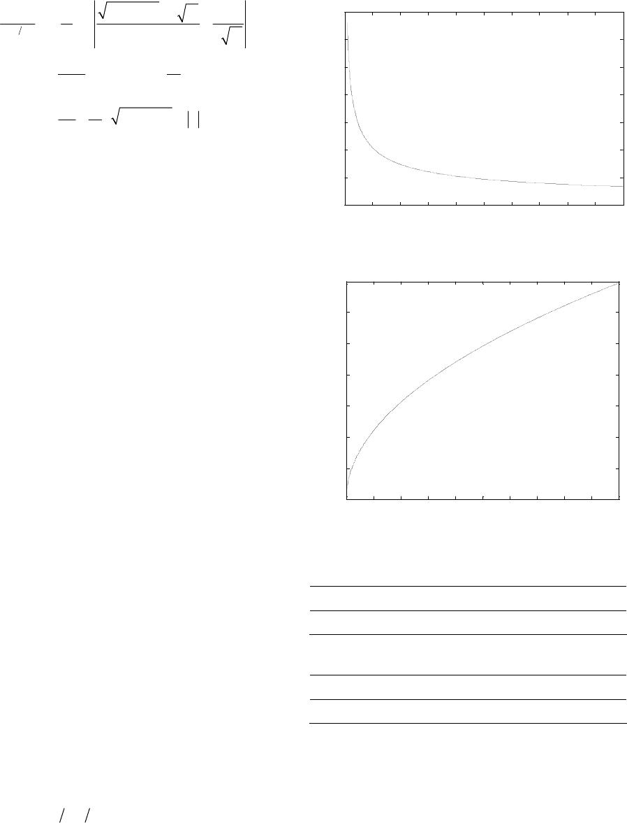 Y. T. WANG ET AL. 199 222 5 11 32 11 2 2 3 22 2 1 ln 2 3arcsin 2 2, 2 Vtxt ab Ax vt xt aa Vt x AxtVt x Vtxx Vt at (67) where: 22 1 aV , 12b , 1c , 22 11 44Dacb V. Using the similar ways as that for finding Equation (33), put |x| = αt into (67) while regarding V, β and t as known constants, respectively. Bridging fiber fracture speed α can be only gained numerical solution, because it can also not be shown in the form of explicit function. 6. Law of Dynamic Stress Intensity Facto In e law of dynamic stress inte s (23), (44) to plot K1(t) as a function of time t, and their numerical solutions are facilely gained. The following constants are as [8,17,21-22,33-36]: C11 = 19.24 GPa; C12 = 1.25 GPa; C11 = 17.83 GPa; P = 200 N; C66 = 1.00 GPa; V = 300 m/s; β = 200 m/s; ρ = 4.9 × 1000 N/m3. Known from Equation (23), dynamic stress int factor K1(t) reduces tardily and has obvious singularity on account of unique variable t in the denominator, and the rest units are regarded as real constants. Such a tend n Figure This variable current is similar to e result of Literatu,17,21,33-38]. It is known fr . 7, r the light of practical situations of concrete problems, mutativ nsity factor should be interpreted better. The corresponding parameters are put into Equation ensity is shown i3. th,22res [8 om Equation (44) that dynamic stress intensity factor K1(t) increases slowly from zero and even reaches or overruns fracture toughness of this material, because sole variable t lies in its numerator, while the rest quantities are also referred to as real constants. This result must conduce the structural instability, as shown in Figure 4 This trend is similar to the result in references [8,1 21,22,33-36,38-40], consequently it is also right. The relative numerical values between dynamic stress intensity factor K1(t) and time t are expressed in Tab l e s 1, 2 in terms of curves in Figures 3, 4, respectively. 7. Conclusions By means of correlative expression: ,, , n xyttfxt yt, where n is an integral number, the problem considered can be facilely changed into ho- mogeneous function of x and t of zeroth dimension, i.e. self-similar functions. All suffice the relationship of this function, and thus the analytical solutions can be gained by Equations (4)-(7) with homogeneous function of 0 2 46 810 1214 16 18 20 0 0.2 0.4 0.6 0.8 1 1.2 1.4 x 10⁻¹¹ t/ms Stress intensity fa ctor K 1 (t )/(N/m 3/2 ) Figure 3. Dynamic stress intensity factor K1(t) versus time t. 0 2 46 810 12 14 16 1820 0 0.5 1 1.5 2 2.5 3 3.5 x 10 14 factor K 1 (t)/(N/m 3/2 ) t/ms S t res s i nt ensi t y Figure 4. Dynamic stress intensity factor K1(t) versus time t. Table 1. Relative numerical values between K1(t) versus t. t/ms 4 8 12 16 20 K1(t) 2.9552 2.0896 1.7062 1.4776 1.3216 Table 2. Relative numerical values between K1(t) versus t. t/ms 4 8 12 16 20 K1(t) 1.5511 2.1936 2.6866 3.1023 3.4684 variable τ. This measure can use not only in electrody- namics [15-20,22,33-34], but also in electrostatics [24,30] and even in other situations, referring to literatures [30, 41]. Analytical solutions of the symmetrical dynamic crack extension model for bridging pull-out of unidirectional composite materials were found by way of the theoretical usage of a complex variable function. The method de- veloped in this paper based on the approaches of the self- similar functions makes it conceivable to obtain the con- Open Access MME  Y. T. WANG ET AL. 200 crete solution of this model and bridging fiber fracture speed α. According to the concrete boundary conditions, self-similar function W(τ) can be easily deducted by means of corresponding to variable τ. Consequently, analytical solutions of stresses, displacements and dy- namic stress intensity factors will be readily worked out. This is referred to as the analogous class of dynamic problem of the elasticity theory. However, the present solution occurs to be the simplest and intuitive of all al- ternative approaches appearing by so far. Indeed, we have succeeded in a mixed Keldysh-Sedov boundary va- lue problem on a half-plane. The query is of adequate actual interest, since all the members of structures in which fractures may move are of finite dimensions are frequently in the modality of long strips. The ways solution are based exclusively on techniques of analyt l m thent ohe comtativerk neo rlve such a crack expansion query. . Acknowledgements (Heading 5) Pro neecentref hydraic andpmeor min of Liaong profT). posites,” Acta Metallurgical, Vol. 33, No. 11, 1985 and of i- cal-function theory and are simple and compendious. By making some observations regarding the soution of the ixed boundary value problem we have rather decreased amouf tpu woeded teso 8 ject is supported by the open foundation of the engi- ring oul equint fing inovince China (No. CMH-201207 REFERENCES [1] D. B. Marshall, B .N. Cox and A .G. Evens, “The Me- chanics of Matrix Cracking in Brittle-Matrix Fiber Com- , pp. 2013-2021. http://dx.doi.org/10.1016/0001-6160(85)90124-5 [2] B. Budiansky, J. W. Hutchinson and A. G. Evens, “Ma- trix Fracture in Fiber-Reinforced Ceramics,” Journal of the Mechanics and Physics of Solids. Vol. 34, No. 2, 1986, pp. 167-189. http://dx.doi.org/10.1016/0022-5096(86)90035-9 [3] M. Ji and H. Ishikawa, “Analysis of an Internal Central Crack with Bridging Fibers in a Finite Orthotropic Plate,” International Journal of Engineering Science, Vol. 35, No. 4, 1997, pp. 549-560. http://dx.doi.org/10.1016/S0020-7225(96)00099-7 [4] D. B. Marshall and B. N. Cox. “Tensile Fracture of Brittle Matrix Composites: Influence of Fiber Strength,” Acta Metallurgical, Vol. 35, No. 11, 1987, pp. 2607-2619. http://dx.doi.org/10.1016/0001-6160(87)90260-4 [5] Z.-M. Wang, “Mechanics and Structural Mechanics of Composite Materials,” Publisher of Machinery Industry, Beijing, 1991. [6] G.-L. Shen. “Mechanics of Composite Materials,” Tsing- hua University Press, Beijing, 1996. [7] C. W. Woo and Y. H. Wang, “Analysis of an Internal Crack in a Fine Anisotropic Plate,” International Journal of Fracture, Vol. 62, No. 2, 1993, pp. 203-208. [8] J. C. Lee, “Analysis of Fiber Bridged Crack near a Free Surface in Ceramic Matrix Composites,” Engineering Fracture Mechanics, Vol. 37, No. 2, 1990, pp. 209-219. http://dx.doi.org/10.1016/0013-7944(90)90344-G [9] W. T. Tsai and I. R. Dharani, “Non Self-Similar Fiber Fracture in Unidirectional Composites,” Engineering p. 43-49. 80-C Fracture Mechanics, Vol. 44, No. 1, 1993, p http://dx.doi.org/10.1016/0013-7944(93)900 1994, pp. 31-35. [11] K. Liao and K.th Model for [10] W. N. Liu, “Stress Ahead of the Tip of a Finite-Width Center-Crack in Fiber-Reinforced Composite Specimens: Subjected to Non-Linearly Distributed Bridging Stresses,” International Journal of Fracture, Vol. 70, No. 1, Reifsnider, “A Tensile Streng Unidirectional Fiber-Reinforced Brittle Matrix Compos- ite,” International Journal of Fracture, Vol. 106, No. 1, 2000, pp. 95-115. http://dx.doi.org/10.1023/A:1007645817753 [12] V. Tamuzs, S. Tarasovs and U. Vilks, “Progressive De- lamination and Fibre Bridging Modeling in Double Can- tilever Beam Composite Specimens,” Engineering Frac- ture Mechanics, Vol. 68, No. 5, 2001, pp. 513-525. http://dx.doi.org/10.1016/S0013-7944(00)00131-4 [13] A. Piva and E. Viola, “Crack Propagation in an Ortho- tropic Media”, Engineering Fracture Mechanics, Vol. 29, No. 5, 1988, pp. 535-547. http://dx.doi.org/10.1016/0013-7944(88)90179-8 [14] J. De and B. Patra, “Elastod Orthotrpic Medium through Complex Variable Appr ynimic Crack Problems in An oach,” k,” Engineering Fracture Mechanics, Vol. 41, No. 5, 1998, pp. 895-909. [15] K. B. Broberg, “The Propagation of a Brittle Crac Arkve Fysik, Vol. 18, No. 2, 1960, pp. 159-192. [16] Y. W. Craggs, “The Growth of a Disk-Shaped Crack,” International Journal of Engineering Science, Vol. 4, No. 2, 1966, pp. 113-124. http://dx.doi.org/10.1016/0020-7225(66)90019-X [17] J. G. Goree and R. S. Gross, “Analysis of a Unidirectional Composite Containing Broken Fibers and Matrix Dam- age,” Engineering Fracture Mechanics, Vol. 33, No. 3, 1979, pp. 555-578. [18] G. P. Cherepanov and E. F. Afanasov, “Some Dynamic Problems of the Theory of Elasticity—A Review,” Inter- national Journal of Engineering Science, Vol. 12, No. 8, 1974, pp. 665-690. http://dx.doi.org/10.1016/0020-7225(74)90043-3 [19] G. P. Charepanov, “Mechanics of Brittle Fracture,” Nau- ka, Moscow, 1973. [20] C. Atkinson, “The Propagation of a Brittle Crack in Anis- tropic Material,” International Journal of Engineering Science, Vol. 3, No. 1, 1965, pp. 77-91. http://dx.doi.org/10.1016/0020-7225(65)90021-2 [21] N.-C. Lü, X.-G. Li, Y.-H. Cheng and J. Cheng, “Fracture Dynamics Problem on Mode I Semi-Infinite Crack,” Ar- chive of Applied Mechanics, Vol. 81, No. 9, 2011, pp. 1181-1193. http://dx.doi.org/10.1007/s00419-010-0476-x [22] N. C. Lü, Y. H. Cheng. X. G. Li and J. Cheng, “Dynamic Propagation Problem of Mode I Semi-Infinite Crack Open Access MME  Y. T. WANG ET AL. Open Access MME 201 racture of a Subjected to Superimpose Loads,” Fatigue & F Engineering Materials & Structures. Vol. 33, No. 3, 2010, pp. 141-148. [23] N. C. Lü, Y. H. Cheng. X. G. Li and J. Cheng, “An Asymmetrical Dynamic Model for Bridging Fiber Pull- Out of Unidirectional Composite Materials,” Meccnica, Vol. 47, No. 5, 2012, pp. 1247-1260. http://dx.doi.org/10.1007/s11012-011-9509-y [24] N. I. Muskhlishvili, “Singul Moscow, 1968. ar Integral Equations,” N , “Boundary-Value Problems,” Fitzmatigiz, orwood auka, [25] N. I. Muskhlishvili, “Some Fundamental Problems in the Mathematical Theory of Elasticity,” Nauka, Moscow, 1966. [26] F. D. Gakhov Moscow, 1963. [27] R. F. Hoskins, “Generalized Functions,” Ellis H, Chichester, 1979. [28] X. S. Wang, “Singular Functions and Their Applications in Mechanics,” Scientific Press, Beijing, 1993. [29] G. C. Sih, “Mechanics of Fracture 4. Elastodynamics Crack Problems,” Noordhoff, Leyden, 1977. [30] R. P. Kanwal and D. L. Sharma, “Singularity Methods for Eastostatics,” Journal of Elasticity, Vol. 6, No. 4, 1976, pp. 405-418. http://dx.doi.org/10.1007/BF00040900 [31] Editorial Group of Mathematics Handbook, “Mathemati- cal Handbook,” Advanced Education Press, Beijing, 2002. [32] Teaching Office of “Advanced Mathematics,” Advanced Education P Mathematics of Tongji University Crack Growth in Anisotropic Mate- . ress, Beijing, 1994. [33] K. C. Wu, “Dynamic rial,” International Journal of Fracture, Vol. 106, No. 1, 2000, pp. 1-12. http://dx.doi.org/10.1023/A:1007621500585 [34] X.-G. Li, Y.-H. Cheng, N.-C. Lv, G.-D. Hao and J. Cheng cal Science and Technology, Vol. 25, , “A Dynamic Asymmetrical Crack Model of Bridging Fi- ber Pull-Out in Unidirectional Composite Materials,” Journal of Mechani No. 9, 2011, pp. 2297-2309. http://dx.doi.org/10.1007/s12206-011-0526-5 [35] N. C. Lv, Y. H. Cheng. H. L. Si and J. Cheng, “Dynamics of Asymmetrical Crack Propagation in Composite Mate- rials,” Theoretical and Applied Fracture Mechanics, Vol. 47, No. 3, 2007, pp. 260-273. http://dx.doi.org/10.1016/j.tafmec.2007.01.004 [36] N. C. Lü, Y. H. Cheng and J. Cheng, “Mode I Crack Tips Propagating at Different Speeds under Differential Sur- face Tractions,” Theoretical and Applied Fracture Me- chanics, Vol. 46, No. 3, 2006, pp. 262-275. http://dx.doi.org/10.1016/j.tafmec.2006.09.004 [37] A. S. Kobayashi, “Dynamic Fracture Analysis by Dy- n Society of Mechanical Engineers, 963460 namic Finite Element Method. Generation and Prediction Analyses,” In: Nonlinear and Dynarnic Fracture Me- chanics, America New York, 1979, pp. 19-36. [38] K. Ravi-Chandar and W. G. Knauss, “An Experimental Investigation into Dynamic Fracture: Part 1, Crack Initia- tion and Arrest,” International Journal of Fracture, Vol. 25, No. 41, 1984, pp. 247-262. http://dx.doi.org/10.1007/BF00 erimental 52313 [39] K. Ravi-Chandar and W. G. Knauss, “An Exp Investigation into Dynamic Fracture: Part 2, Microstruc- tural Aspects,” International Journal of Fracture, Vol. 26, No. 11, 1984, pp. 65-80. http://dx.doi.org/10.1007/BF011 erimental [40] K. Ravi-Chandar and W. G. Knauss, “An Exp Investigation into Dynamic Fracture: Part 3, on Steady- State Crack Propagation and Crack Branching,” Interna- tional Journal of Fracture, Vol. 26, No. 2, 1984, pp. 141- 152. http://dx.doi.org/10.1007/BF01157550 [41] L. A. Galin, “Contact Problems in Elasticity Theory,” GITTL, Moscow, 1953.
|