Journal of Computer and Communications, 2013, 1, 32-35
Published Online December 2013 (http://www.scirp.org/journal/jcc)
http://dx.doi.org/10.4236/jcc.2013.17008
Open Access JCC
An Economic Phase-Mdulation to Intensity-Modulation
Converter
Ching-Hung Chang1*, Jui-Hsuan Chang2, Yin-Liang Liao2, Meng Chun Tseng2
1Department of Electrical Engineering, National Chiayi University; 2Department of Computer Science and Information Engineering
National Chiayi University.
Email: *chchang@mail.ncyu.edu.tw
Received September 2013
ABSTRACT
A novel phase-modulation to intensity-modulation (PM-to-IM) converter is proposed and experimentally demonstrated
basing on a vertical-cavity surface-emitting laser (VCSEL). Comparing with the published schemes, in which the em-
ployed DI, FBG, OBPF or dispersion devices can only process a certain phase-modulated RF signal, the proposed
scheme can achieve the conversion process in an economic and resourceful manner. To be the first one of achieving
such PM-to-IM conversion process by a VCSEL, the feasibility of the propos al is experimentally demonstrated with an
open eye diagram when it is employed to convert phase-modulated RF signal.
Keywords: Long-Reach PON; Phas e Modulation; Vertical-Cavity Surface-Emitting Laser
1. Introduction
With standard single mode fiber (SMF) and conventional
optical external intensity modulators, such as Mach-
Zehnder modulator (MZM), microwave signal can be eas-
ily modulated with an optical carrier and communicated
to its destination [1,2]. Nevertheless, an optimized DC
bias is required to add on the MZM to obtain high quality
optical microwave signal. Different with utilizing the
MZM to generate the optical microwave signals, an opt-
ical phase modulator (PM) can simply utilize the optical
phase shifting to record the microwave states without a
need of a DC bias to control the operating point of the
electrical to optical conversion processes, so it will not
suffer from the DC bias-drifting problem [3]. Besides,
such PM systems can efficiently against unwanted self-
phase-modulation (SPM) and cross-phase-modulation
(XPM) effects as well as eliminate cross-gain-modulation
(XGM) effects since the envelope of the generated phase-
modulated signal is constant [4 ,5 ].
In an optical phase modulation system, the PM signal
with a constant envelope needs to be converted into IM
signal format before being detected by a PD which only
can detect the variation of the optical inten sity. Tradition-
ally, such phase modulation to intensity modulation (PM-
to-IM) conversion process can be achieved by inserting a
delay line interferometer (DI) in front of the PD. Never-
theless, the DI itself is sophisticated and expensive.
Adding it into an optical transport link will significantly
reduce the advancements of the PM scheme. In order to
overcome this drawback, multiple PM-to-IM conversion
schemes have been developed basing a fiber Bragg grat-
ing (FBG) [6-8] or an optical band-pass filter (OBPF)
[9,10]. By reflecting or filtering out one of the +1 or 1
sideband of the received optical phase-modulated signal,
a PD will be able to directly convert the received signal
back into electrical domain. In addition to filter out one
of the sideband, an optical PM-to-IM conversion scheme,
is developed based on a dedicated dispersive devices in
which are employed to introduce a dispersion-induced
PM-to-IM conversion [11-13]. Under these structures,
the overall construction cost could be reduced. However,
utilizing the fiber dispersion to achieve such PM-to-IM
conversion requires a high wavelength stability and a
dedicated dispersion value to maximum PM-to-IM con-
version. It is not flexible in a WDM transport system. In
order to provide an economic and simplify structure to
achieve the PM-to-IM conversion process with adjusta-
ble microwave frequency range, a novel PM-to-IM con-
verter is proposed.
In this proposal, a vertical-cavity surface-emitting la-
ser (VCSEL) and an optical circulator (OC) are com-
posed as a tunable optical notch amplifier and is utilized
to achieve the PM-to-IM convers ion process by boo sting
up the +1 or 1 sideband of the phase-modulated signal.
Experimental results proof that the frequency tuning
*
Corresponding author.
An Economic Phase-Mdulation to Intensity-Modulation Converter
Open Access JCC
33
range of the notch amplifier is more than 300 GHz. This
proposal is shown to be an outstanding candidate to achi-
eve long-distance RoF trans por t systems.
2. Operation Principle and Experimental
Results
The experimental setup of the proposed tunable PM-to-
IM converter is shown in the center yellow box of Fig-
ure 1, where an OC, a polarization controller (PC) and a
commercial VCSEL are employed. In this setup, an opt-
ical carrier is firstly phase-modulated with a microwave
signal via a PM and then injected into the tunable PM-
to-IM converter to verify the converter performance. The
injected lightwave will be routed and fed into the VCSEL
by the OC. Subsequently, the reflected lightwave will be
routed by the OC again and then fed into a PD. In this
structure, if the +1 sideband of the injected phase-mod-
ulated signal, as shown in the insert (i) of the Figure 1, is
aligned with the lasing wavelength of the VCSEL an
optical amplification process will be introduced into the
+1 sideband, as shown in the insert (ii) of the Figure 1.
This is because that when the photons of the +1 sideband
propagate through and back the laser cavity of the
VCSEL, they will hit excited electrons inside the cavity
and thus forcing new photon to be emitted at the same
wavelength. Once the VCSEL is lasing, the stimulated
emission will dominate over stimulated absorption pro-
ducing an optical gain for the +1 sideband. As shown in
the insert (iii) of the Figure 1, the beating amplitude of
the center carrier and the +1 sideband will therefore larg-
er than that of the center carrier and the 1 sideband at
the PD so the PD can successfully convert the phase-mod-
ulated signal back into electronic domain. In order to
verify the proposal, a 1.25 Gbps/10GHz signal is expe-
rimentally phase modulated with the downstream before
being detected by a PD. In an optical phase modulation
system, if there is only a single-frequency sinusoidal
signal with zero initial phase is modulated, the electrical
field of a phase-modulated optical carrier ePM(t) can be
expressed as [14]:
( )
( )
00
1
( )cosπ2
PMnPM em
n
eteJVwnw tn
β
+∞
=−∞

= ++


(1)
where the e0 and w0 are the amplitude and the angular
frequency of the optical carrier. Jn() denotes the nth-
order Bessel function of the first kind. βPM is the phase
modulation index (radians per volt). Ve and wm are the
amplitude and angular frequency of the modulating sig-
nal. For simplicity, the argument ( βPMVe) will be omitted
in the remainder of this paper and only the first-order
upper and lower sidebands are considered. The small
signal assumption of (1) can be further simplified as [25]:
( )
( )
( )
000 10
10
π
cos cos2
π
cos 2
PM
m
eteJw tJwwmt
Jw wt

=+ ++



+ −−


(2)
Figure 1. Schematic diagram of the proposed tunable PM-to-IM converter basing on a vertical-cavity surface-emitting laser.
(TL: tunable laser, PC: polarization controller, PM: phase modulator, OC: optical circulator, VCSEL: vertical-cavity sur-
face-emitting laser, PD: photodetector, SG: signal generator, ESA: electronic spectrum analyzer).
IM Signal
+1
-1
PM Signal
(i)
+1
-1
(iii)RF Spectrum
f
m
+1 sideband
-1 sideband
TL PM
ESA
PD
OC
VCSEL
PC
Tunable
PM-to-IM
Converter
SG
(i)
PC
(iii)
(ii)
(ii)
An Economic Phase-Mdulation to Intensity-Modulation Converter
Open Access JCC
34
For Bessel function, the Jn is equal to -j-n when n is
odd. From (2), we can find that if the phase modulated
signal is directly injected into a PD, the center carrier
will individually beats with +1 and 1 sidebands, result-
ing in two electrical signals with the same amplitude, the
same frequency but different phase. So the PD will not
have any output signal. Nevertheless, when the phase-
modulated signal is injected into the proposed tunable
IM-to-PM converter, the optical intensity of the +1 side-
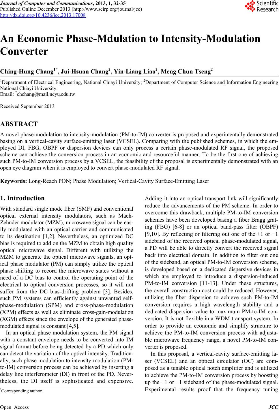
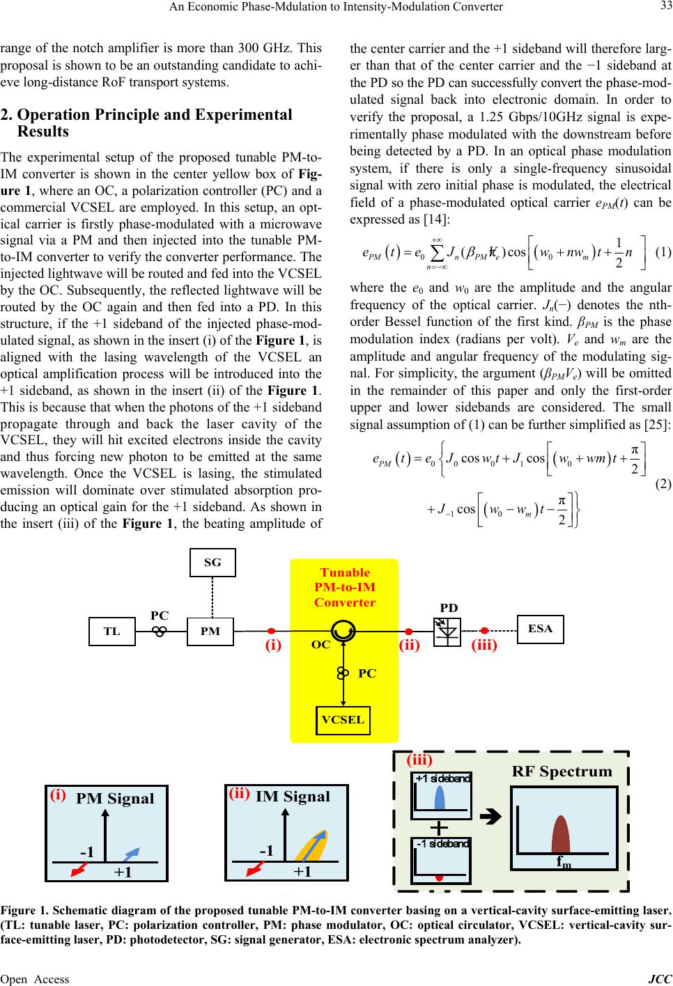
band will be boosted up. As shown in Figures 2 and 3,
the optical power variation between the +1 and 1 side-
bands is significantly promoted from 0 dB to 26 dB. A
clear eye diagram and obvious electronic spectrum are
shown proof in Figure 3. This means that the proposed
tunable PM-to-IM converter can successfully modify the
received phase-modulated signal back into intensity-
modula t ion form a t .
3. Conclusion
In this paper, a novel PM-to-IM converter is proposed
Figure 2. The optical spectrum of phase-modulated RF sig-
nal.
Figure 3. The optical spectrum of phase-modulated RF sig-
nal after passing though the PM-to-IM converter.
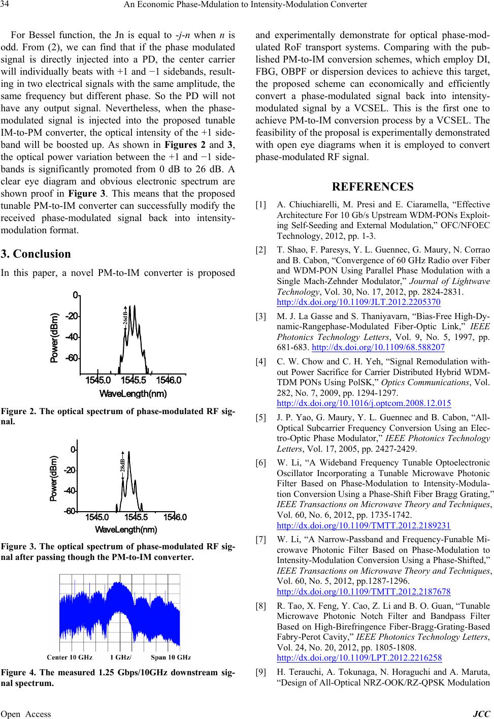
Figure 4. The measured 1.25 Gbps/10GHz downstream sig-
nal spectr um .
and experimentally demonstrate for optical phase-mod-
ulated RoF transport systems. Comparing with the pub-
lished PM-to-IM conversion schemes, which employ DI,
FBG, OBPF or dispersion devices to achieve this target,
the proposed scheme can economically and efficiently
convert a phase-modulated signal back into intensity-
modulated signal by a VCSEL. This is the first one to
achieve PM-to-IM conversion process by a VCSEL. The
feasibility of the propos al is experimentally d emonstr ated
with open eye diagrams when it is employed to convert
phase-modulated RF signal.
REFERENCES
[1] A. Chiuchiarelli, M. Presi and E. Ciaramella, Effective
Architecture For 10 Gb/s Upstream WDM-PONs Exploit-
ing Self-Seeding and External Modulation,OFC/NFOE C
Technology, 2012, pp. 1-3.
[2] T. Shao, F. Paresys, Y. L. Guennec, G. Maury, N. Corrao
and B. Cabon, “Convergence of 60 GHz Radio over Fiber
and WDM-PON Using Parallel Phase Modulation with a
Single Mach-Zehnder Modulator,” Journal of Lightwave
Technology, Vol. 30, No. 17, 2012, pp. 2824-2831.
http://dx.doi.org/10.1109/JLT.2012.2205370
[3] M. J. La Gasse and S. Thaniyavarn, “Bias-Free High-Dy-
namic-Rangephase-Modulated Fiber-Optic Link,IEEE
Photonics Technology Letters, Vol. 9, No. 5, 1997, pp.
681-683. http://dx.doi.org/10.1109/68.588207
[4] C. W. Chow and C. H. Yeh, Signal Remodulation with-
out Power Sacrifice for Carrier Distributed Hybrid WDM-
TDM PONs Using Pol SK,Optics Communications, Vol.
282, No. 7, 2009, pp. 1294-1297.
http://dx.doi.org/10.1016/j.optcom.2008.12.015
[5] J. P. Yao, G. Maury, Y. L. Guennec and B. Cabon, All-
Optical Subcarrier Frequency Conversion Using an Elec-
tro-Optic Phase Modulator,IEEE Photonics Technology
Letters, Vol. 17, 2005, pp. 2427-2429.
[6] W. Li, A Wideband Frequency Tunable Optoelectronic
Oscillator Incorporating a Tunable Microwave Photonic
Filter Based on Phase-Modulation to Intensity-Modula-
tion Conversion Using a Phase-Shift Fiber Bragg Grating,
IEEE Transactions on Microwave Theory and Techniques,
Vol. 60, No. 6, 2012, pp. 1735-1742.
http://dx.doi.org/10.1109/TMTT.2012.2189231
[7] W. Li, A Narrow-Passband and Frequency-Funable Mi-
crowave Photonic Filter Based on Phase-Modulation to
Intensity-Modulation Conversion Using a Phase-Shifted,”
IEEE Transactions on Microwave Theory and Techniques,
Vol. 60, No. 5, 2012, pp.1287-1296.
http://dx.doi.org/10.1109/TMTT.2012.2187678
[8] R. Tao, X. Feng, Y. Cao, Z. Li and B. O. Guan, “Tunable
Microwave Photonic Notch Filter and Bandpass Filter
Based on High-Birefringence Fiber-Bragg-Grating-Based
Fabry-Perot Cavity,” IEEE Photonics Technology Letters,
Vol. 24, No. 20, 2012, pp. 1805-1808.
http://dx.doi.org/10.1109/LPT.2012.2216258
[9] H. Terauchi, A. Tokunaga, N. Horaguchi and A. Maruta,
Design of All-Optical NRZ-OOK/RZ-QPSK Modulation
26dB
1545.0 1545.5 1546.0
- 60
- 40
- 20
0
Pow er(dBm)
WaveLengt h(nm)
1545.0 1545.5 1546.0
-60
-40
-20
0
Pow er(dB m)
WaveLength(nm)
28dB
An Economic Phase-Mdulation to Intensity-Modulation Converter
Open Access JCC
35
Format Converter by Use of Cross Phase Modulation in
Optical Fiber,” OptoElectronic s and Communicat ions Con-
ference, July 2012, pp. 899-900.
[10] Y. Du and G. P. Zhang, “Photonic Data Selector Based
on Cross-Phase Modulation in a Highly Nonlinear Fiber,
In Photo and Optoelectron, May 2012, pp. 1-3.
[11] X. Wu, X. Zheng, S. Li, H. Wen, Y. Guo and H. Zhang,
“Multisideband Detection Radio-Over-Fiber Link with
Phase Modulation and Fiber Demodulation for Vector
Signal Transmission,” IEEE Photonics Technology Let-
ters, Vol. 22, 2010 pp. 76-78.
http://dx.doi.org/10.1109/LPT.2009.2036145
[12] B. Yang, X. Jin, H. Chi, X. Zhang, S. Zheng, S. Zou, H.
Chen, E. Tangdiongga and T. Koonen, “Optically Tuna-
ble Frequency-Doubling Brillouin Optoelectronic Oscil-
lator with Carrier Phase-Shifted Double Sideband Mod-
ulation,” IEEE Photonics Technology Letters, Vol. 24,
2012, pp. 1051-1053.
http://dx.doi.org/10.1109/LPT.2012.2194483
[13] R. Tao, X. Feng, Y. Ca o, Z. Li and B. O. Guan, Widely
Tunable Single Bandpass Microwave Photonic Filter Ba-
sed on Phase Modulation and Simulated Brillouin Scat-
tering,” IEEE Photonics Technology Letters, Vol. 24,
2012, pp. 1097-1099.
http://dx.doi.org/10.1109/LPT.2012.2195486
[14] J. Yao, F. Zeng and Q. Wang, “Photonic Generation of
Ultrawideband Signal s,IEEE/OSA Journal of Lightwave
Technology, Vol. 25, 2007, pp. 3219-3235.