 Journal of Computer and Communications, 2013, 1, 9-13 Published Online December 2013 (http://www.scirp.org/journal/jcc) http://dx.doi.org/10.4236/jcc.2013.17003 Open Access JCC The Circular Biref ri n genc e -Insensitive FBG Sensor for Weak Pressu r e Hui Peng, Bi-hua Zhou, Li-hua Shi, Cheng Gao National Key Laboratory on Electromagnetic Environment Effects and Electro-optical Engineering, PLA University of Science and Technology, Nanjing, Jiangsu, China. Email: njnice99@163.com Received August 2013 ABSTRACT The influence of the circular birefringence on the measurement performance was analyzed based on the Polarization Properties of FBG in this paper. Due to the circular birefringence, the linear relationship between the max of PDL and pressure has been broken down. To estimate the cross sensitivity, a new parameter named relative peak of PDL (RPPDL) is proposed. Under different circular birefringence, the same pressure sensitivity of sensor has been achieved. The theo- retical analysis and experiment results prove that transverse strain sensor of FBG is insensitive to the circular birefrin- gence by applying the RPPDL. This res e a rch can be provide d to useful and practical application . Keywords: Circularly Birefringence; Polarization Propertied; FBG Weak Pressure S ensor; The Relative Peak of PDL (RPPDL) 1. Introduction For both telecommunications and sensing purposes, FBG thus becomes important to characterize the polarization properties of FBG and their dependence on the wave- length [1-3]. Furthermore, this study can lead to the de- velopment of a new demodulation technique for FBG- based sensors. Caucheteur et al. have used polarization dependent loss (PDL) for transverse strain measurements [4,5]. The polarization dependent properties are also used for the magnetic field sensor [6]. Either way, there exist cross-sensitivity problems. In wavelength detection, the centre wavelength will change not only with the strain, but also with the temperatur e [7]. Similarly, in polarization detection, the polarization pro p - erties are influenced by the linear and circular birefrin- gence [8,9]. Hence, we must take various kinds of meas- ures to compensate or distinguish the cross-sensitivity problems. A number of techniques addressing this issue, such as dual-wavelength superimposed grating, two FBGs in different diameter fiber, hybrid FBG/long period grat- ing, superstructure FBG and Fabry-Perot cavity method, have be en reported [10-12]. Those methods provided some approaches to distinguish cross-sensitivity e ffect, b ut most of them needed specific gratings and special technique. In this paper, the influence of the circular birefrin gence on the measurement performance was analyzed based on the polarization properties o f FBG. To estimate the cross sensitivity, a new parameter named relative peak of PDL (RPPDL) is proposed. The simulation and experiment re- sults proved that the relative peak of PDL (RPPDL) could effectively reduce the influence of circular birefringence. 2. Theoretical Models 2.1. Principle of Measurement The polarization property of FBG has been widely used in the field of measurement. Here, we shortly introduce the principle of measurement. The applied force causes a birefringence Δn, which is defined as the difference in refractive index between two orthogonal polarization modes called x and y modes (or eigenmodes). Due to the Δn, the x and y modes undergo different couplings through the grating. The total trans- mitted signal is the combination of th e x and y mode sig- nals. If there is only the linear birefringence, the Jones vector associated to the FBG transmitted signal is given by [5]: , ,, , ,, 0 0 txixx ix x y tyiyyiy EEtE tt EE tE = = (1) Where (Ei,x, Ei,y)T is the Jones vector of the input signal and tx(y) denotes the transmission coefficient of x(y) mode FBG [13]. Polarization Dependent Loss (PDL) is defined as the 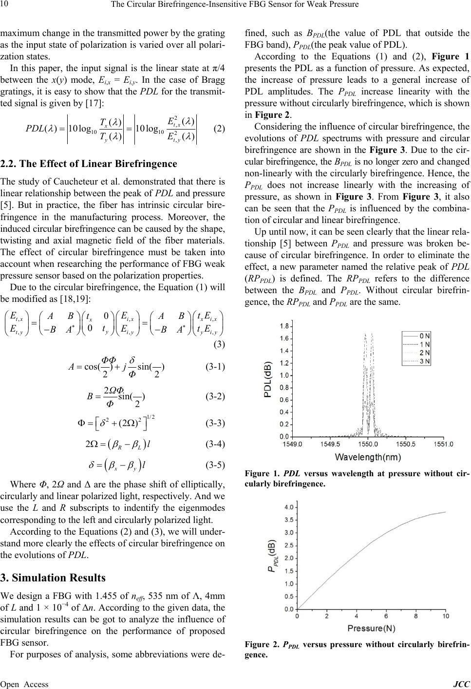 The Circular Birefringence-Insensitive FBG Sensor for Weak Pressure Open Access JCC maximum change in the transmitted power by the grating as the input state of polarizatio n is varied over all polari- zation states. In this paper, the input signal is the linear state at π/4 between the x(y) mode, Ei,x = Ei,y. In the case of Bragg gratings, it is easy to show that the PDL for the transmit- ted signal is given by [17]: 2 , 1010 2 , () () ( )10log10log () () tx x yty E T PDL TE λ λ λλλ = = (2) 2.2. The Effect of Linear Birefringence The study of Caucheteur et al. demonstrated that there is linear relationship between the peak of PDL and pressure [5]. But in practice, the fiber has intrinsic circular bire- fringence in the manufacturing process. Moreover, the induced circular birefringence can be caused by the shape, twisting and axial magnetic field of the fiber materials. The effect of circular birefringence must be taken into account when researching the performance of FBG weak pressure sensor based on the polarization properties. Due to the circular birefringence, the Equation (1) will be modified as [18,19]: , ,, , ,, 0 0 txixx ix x y tyiyyiy EEtE t AB AB t EE tE BA BA ∗∗ = = −− (3) (3-1) (3-2) (3 -3) (3-4) (3-5) Where Φ, 2Ω and Δ are the phase shift of elliptically, circularly and linear polarized light, respectively. And we use the L and R subscripts to indentify the eigenmodes corresponding to the left and circularly polarized light. According to th e Equations (2) and (3), we will under- stand more clearly the effects of circular birefringence on the evolut ions of PDL. 3. Simulation Results We design a FBG with 1.455 of neff, 535 nm of Λ, 4mm of L and 1 × 10 −4 of Δn. According to the given data, the simulation results can be got to analyze the influence of circular birefringence on the performance of proposed FBG sensor. For purposes of analysis, some abbreviations were de- fined, such as BPDL(the value of PDL that outside the FBG band), PPDL(the peak value of PDL). According to the Equations (1) and (2), Figure 1 presents the PDL as a function of pressure. As expected, the increase of pressure leads to a general increase of PDL amplitudes. The PPDL increase linearity with the pressure without circular ly b irefringen ce, which is shown in Figure 2. Considering the influence of circular birefringence, the evolutions of PDL spectrums with pressure and circular birefringence are shown in the Figure 3. Due to the cir- cular birefringence, the BPDL is no longer zero and changed non-linearly with the circularly birefringence. Hence, the PPDL does not increase linearly with the increasing of pressure, as shown in Figure 3. From Figure 3, it also can be seen that the PPDL is influenced by the combina- tion of circular and linear birefringence. Up until now, it can be seen clearly that the linear rela- tionship [5] between PPDL and pressure was broken be- cause of circular birefringence. In order to eliminate the effect, a new parameter named the relative peak of PDL (RPPDL) is defined. The RPPDL refers to the difference between the BPDL and PPDL. Without circular birefrin- gence, the RPPDL and PPDL are the same. Figure 1. PDL versus wavelength at pressure without cir- cularly birefringence. Figure 2. PPDL versus pressure without circularly birefrin- gence.  The Circular Birefringence-Insensitive FBG Sensor for Weak Pressure Open Access JCC Figure 3. the evolutions of PDL at different circularly bire- fringence and pressure (CB = circular birefringence). Under circular birefringence, the evolutions of RPPDL were shown in Figure 4. From which it can be seen that the four RPPDL lines were almost coincided under differ- ence circular birefringence (solid, dash, dot and dash dot). Figure 4 means that the RPPDL is insensitive to the circu- lar birefringence. Hence, the influence of circular bire- fringence on the performances of the FBG pressure sen- sors can be eliminated by using the RPPDL. 4. Experiment Results The experimental data were then compared to theoretical evolutions. For that purpose, the experiment system was set up. The optical vector analyzer (OVA) is regarded as a light source, detector and processor. The FBG that used in experiment was designed and fabricated by our project group. The parameters of FBG are: neff = 1.455, Λ = 535 nm, Δn = 5e−5 and L = 10 mm. The width of glass plate is the same size as the length of FBG. The fixture was used to generate the random circular birefringence by twisted the FBG, in this way, only the qualitative method can be used to analyze the circular birefringence. Due to the experimental condition limitations, the applied pressure was in the range 1 ~ 10 N by steps of 1 N. The results under two random conditions with different circular bire- fringence were calculated and analyzed in this section. Using the optical vector analyzer whose precision is 10−5 (dB) in our experiment [20], the PDL evolutions for different pressure under two cases (different circular bi- refringence) are got and shown in Figure 5. The PPDL becomes more and more obvious along with the increase of pressure. To observe Figures 3 and 4, the simulation results and experiment results were similar. Based on different pressure and circular birefringence, the experimental data of the BPDL, PPDL and RPPDL values respectively are given in Table 1. From the Figure 6, we can find that the two set of data about RPPDL and their fitting curves have a good agree- ment, which demonstrates that the RPPDL is not influ- Figure 4. the evolutions of RPPDL at different circularly bi- refringence with same pressure (CB = circular birefrin- gence). (a) case 1 (b) case 2 Figure 5. PDL versus wavelength at pressure for two cases. enced by the circular birefringence. In addition, due to the values of the fitting curves are increase monotonical- ly with pressure, the RPPDL can be used to retrieve the pressure. Based on calculations, the pressure sensitivity are same 0.229 dB/N. Figure 6 also presents the theoret- ical results, the pressure sensitivity of which is 0.291 dB/N. The error between the experiment and theoretical results is caused by the manufacturing error of the FBG, such as the photo-induced birefringence [21,22]. The 1547.2 1547.4 1547.6 1547.8 1548.0 1548.2 1548.4 3 4 5 6 7 8 9 10 11 PDL(dB) Wavel ength( nm) 0 N 5 N 10N 1547.2 1547.4 1547.6 1547.8 1548.0 1548.2 1548.4 6 7 8 9 10 11 12 13 14 PDL(dB) Wavel e ngth(nm) 0 N 5 N 10N  The Circular Birefringence-Insensitive FBG Sensor for Weak Pressure Open Access JCC Table 1. the experimental results for two cases. Pressure/N Case 1 Case 2 BPDL/dB PPDL/dB RPPDL/dB BPDL/dB Peak/dB RPPDL/dB 0 10.94447 11.60567 0.6612 13.35158 14.01735 0.66577 1 9.7146 10.36974 0.65514 11.3351 12.0727 0.7376 2 6.94343 7.77878 0.83535 7.40321 8.23232 0.82911 3 6.7089 8.0723 1.3634 7.5258 8.8028 1.277 4 7.69596 9.12483 1.42887 8.1061 9.5944 1.4883 5 5.79927 7.7797 1.98043 6.86557 8.69737 1.8618 7 5.8658 7.91799 2.05219 6.98792 9.12278 2.13486 8 6.37788 8.56389 2.18601 7.97609 10.19856 2.2225 9 5.35373 7.74207 2.38834 6.08897 8.56583 2.47686 10 6.3616 9.35989 2.99829 7.97609 10.95309 2.977 Figure 6. Evolution of RPPDL in response to a change of pressure. initial value of RPPDL both are 0.66 under two conditio ns because of the intrinsic birefringence. The theoretical analysis and experiment results prove that the errors caused by the circular birefringence can be effectively elimi na t e d by using t he RPPDL. 5. Conclusion By analyzing the influences of the circular birefringence on the performance of the FBG pressure sensor, it is known that the nonlinear relationship between the PPDL and the pressure can be caused by the circular birefrin- gence, which affects the accuracy of the FBG pressure sensor based on the PPDL. For overcoming this weakness, the parameter denoted by RPPDL is proposed in this paper which can ensure the linear relationship between the RPPDL and the pressure under the different circular bire- fringence, thus the pressure can be retrieved by the val- ues of the RPPDL. Th e theoretical analysis and experiment results prove that the errors caused by the circular bire- fringence can be effectively eliminated by using the RPPDL. This research is helpful to the practical applica- tion of the FBG weak pressure sensor, such as underwa- ter acoustic and liquid level measurement, etc. 6. Acknowledgements This work was supported by the National Natural Science Foundation of c hina under GRANT 61271106, the Jiangsu Province Natural Science Foundation BK2012508 and China Postdoctoral Science Foundation funded project (2012M521850). We would like to thank Prof. Xiangfei Chen of Nanjing University for providing OVA in expe- riment. REFERENCES [1] X. F. Yang, C. Y. Zhang, Z. R. Tong, et al., “Experimen- tal Research of Temperature Sensing Properties of a Nov- el Fiber Grating,” Chinese Journal of Lasers, Vol. 38, No. 4, 2011, Article ID : 0405005. [2] Y. Yu, Z. Meng and H. Luo, “Study of Fiber Bragg Grat- ing Vibrating Sensors with Symmetry Push-Pull Confi- guration,” Semiconductor Optoelectronics, Vol. 32, No. 1, 2011, pp. 118-122. [3] Y. N. Zhu, P. Shum, C. Lu, et al., “Temperature-Insensi- tive Fiber Bragg Grating Accelerometer,” IEEE PTL, Vol. 15, No. 10, 2003, pp. 1437-1439. [4] C. Caucheteur, S. Bette, R. Garcia-Olcina, et al., “Trans- verse Force Sensor Exploiting the Birefringence Effect in Uniform Fibre Bragg Gratings,” Proceedings of SPIE, Vol. 6585, 2007, 65850C/1-12 http://dx.doi.org/10.1117/12.722457 [5] C. Caucheteur, S. Bette and R. Garcia-Olcina, “Trans- verse Strain Measurements Using the Birefringence Ef- fect in Fiber Bragg Grating,” IEEE Photo Technology Letter, Vol. 19, No. 13, 2007, pp. 966-968. [6] H. Peng, Y. Su and Y. Q. Li, “Analysis of a New Mag- netic-Field Based on Polarized Parameters of Fiber Grat- ing,” Journal of Microwaves, Vol. 25, No. 5, 2009, pp. 88-96. [7] B. Zhang, G. S. Yan and Y. J. Deng, “Cross-Sensitivity of Fiber Grating Sensor Measurement,” Journal of Applied Optics, Vol. 28, No. 5, 2007, pp. 614-618. [8] F. Kui, Z. Yong, S. Yang and P. Hui, “Analysis of the Cross Sensitivity of Magnetic Field Sensor with Phase-  The Circular Birefringence-Insensitive FBG Sensor for Weak Pressure Open Access JCC Shift Grating,” Acta Optica Sinica, Vol. 30, No. 4, 2010, pp. 1020-1025. [9] Y. Su, B. F. Zhang, Y. Zhu and Y. Q. Li, “Sensing Cir- cular Birefringence by Polariz ation-Dependent Parame- ters in Fiber Bragg Gratings and the Influence of Linear Birefringence,” Opt. Fiber Technol, Vol. 18, 2012, pp. 51-57. http://dx.doi.org/10.1016/j.yofte.2011.11.007 [10] S. H. Aref, H. Latifi, M. I. Zibai and M. Afshari, “Fiber Optic Fabry-Perot Pressure Sensor with Low Sensitivity to Temperature Changes for Downhole Applic ati on,” Op- tics Communications, Vol. 269, No. 2, 2007, pp. 322-330. [11] X. J. Ni, Y. Zhao and J. Yang, “Research of a Novel Fiber Bragg Grating Underwater Acoustic Sensor,” Sensors and Actuators A: Physical, Vol. 138, No. 1, 2007, pp. 76-80. [12] Y. P. Wang, Y. J. Rao, Z. L. Ran, T. Zhu and X. K. Ze ng, “Bend-Insensitive Long-Period Fiber Grating Sensors,” Optics and Laser in Engineering, Vol. 41, No. 1, 2004, pp. 233-239. [13] T. Erdogan, “Fiber Grating Spectra,” J. Llightwave Tec h- nol., Vol. 15, No. 8, 1997, pp. 1277-1294. http://dx.doi.org/10.1109/50.618322 [14] Z. Z. Li, “Theoretical and Experimental Research on Sensing Characteristics of Birefringenct Fiber Grating,” National University of Defense Technology, 2006 [15] R. B. Wagreich, E. A. Altia, H. Singh and J. S. Sirkis, “Effects of Diametric Load on Fibre Bragg Gratings in Low Birefringence Fibre,” Electron. Lett., Vol. 32, No. 13, 1996, pp. 1223-1224. http://dx.doi.org/10.1049/el:19960806 [16] C. M. Lawrence, D. V. Nelson, E. Udd and T. Bennett, “A Fiber Optic Sensor for Transverse Strain Measure- ment,” Exp. Mech., Vol. 39, No. 3, 1999, pp. 202-209. http://dx.doi.org/10.1007/BF02323553 [17] S. Bette, C. Caucheteur, M. Wuilpart, et al., “Theoretical and Experimental Study of Differential Group Delay and Polarization Dependent Loss of Bragg Gratings Written in Birefringent Fiber,” Optical Communication, Vol. 2. No. 269, 2007, pp. 331-337. [18] Z. P. Wang, Q. B. Li, X. Y. Liu, et al., “Theoretical Ana- lysis of the Effects of the Linear Birefringence upon the Performance of a Bulk Glass Optical Current Sensor,” Acta Photonica Sinica, Vol. 33, No. 7, 2004, pp. 818-822. [19] A. M. Smith, “Polarization and Magneto-Optic Properties of Single-Mode Optical Fiber,” Applied Optics, Vol. 17, No. 1, 1978, pp. 52-56. [20] Optical Vector Analyzer User Guide, Document version 4. 7 for OVA control software version 3. 7. 1 m 2006 Luna Technologies, Inc [21] H. Peng, “Research on Magnetic Field Measurement Bas- ed on Polarization Properties of Fiber Bragg Grating,” Ph.D. Dissertation, PLA University of Scie nce and Tech- nology, Nanjing, 2009 [22] C. Caucheteur, S. Bette, F. Lhommé, et al., “Numerical Reconstruction of Induced Birefringence in Uniform Fi- ber Bragg Gratings Through Polarization Properties Mea- surement,” Proceedings of 2005 IEEE/LEOS Workshop on Fibres and Optical Passive Components, 2005, pp. 228-233.
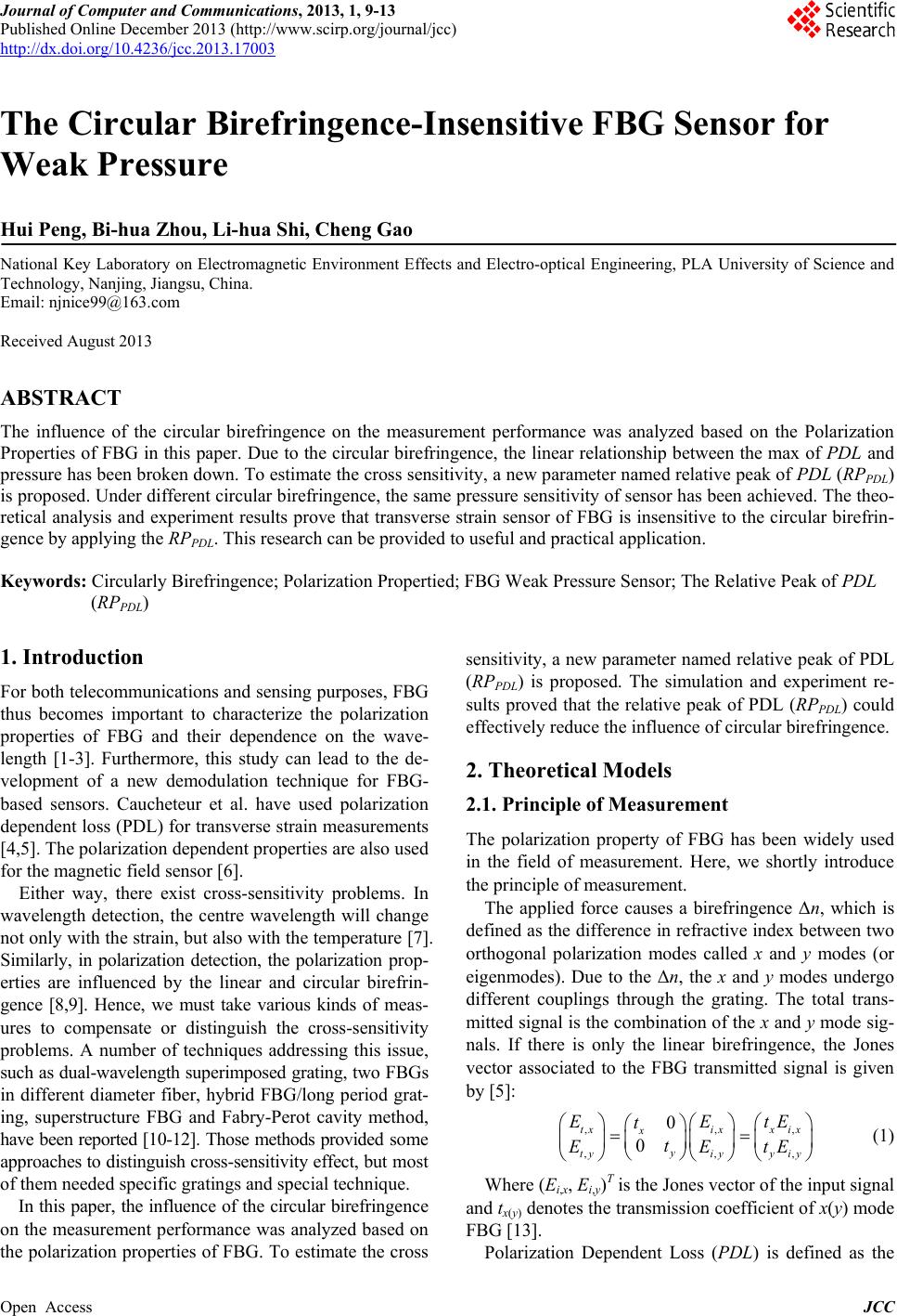
|