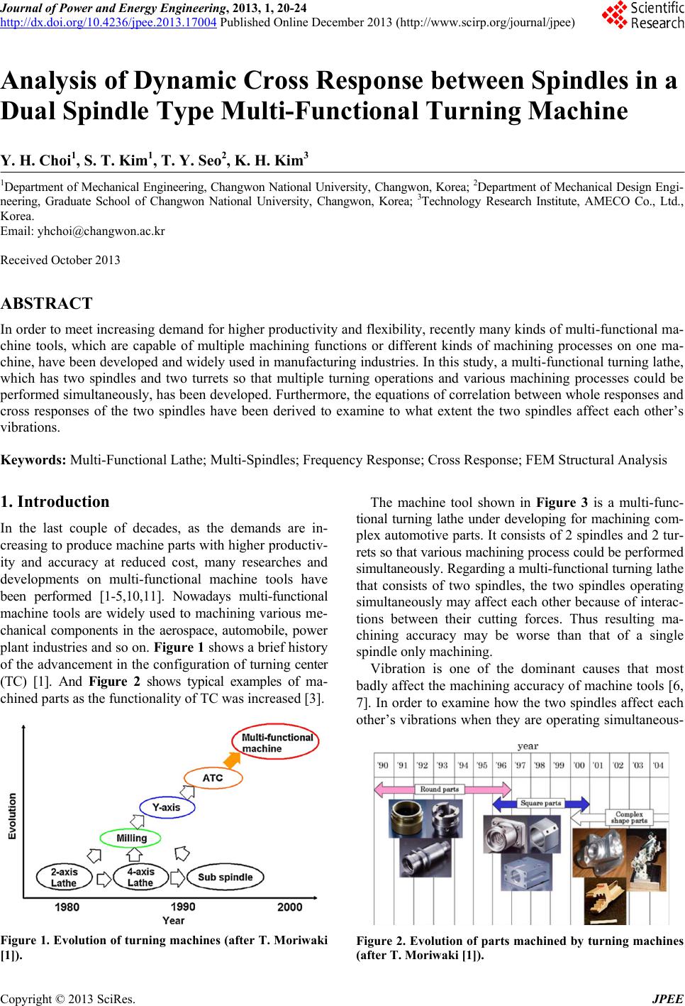
 Journal of Power and Energy Engineering, 2013, 1, 20-24 http://dx.doi.org/10.4236/jpee.2013.17004 Published Online December 2013 (http://www.scirp.org/journal/jpee) Copyright © 2013 SciRes. JPEE Analysis of Dynamic Cross Response between Spindles in a Dual Spindle Type Multi-Functional Turning Machine Y. H. Choi1, S. T. Kim1, T. Y. Seo2, K. H. Kim3 1Department of Mechanical E ngineering, Changwon National Uni versity, Changwon, Korea; 2Depart ment of Mechanical Design Engi- neering, Graduate School of Changwon National University, Changwon, Korea; 3Technology Research Institute, AMECO Co., Ltd., Korea. Email: yhchoi@changwon.ac.kr Received October 2013 ABSTRACT In order to meet increasing demand for higher productivity and flexibility, recently many kinds of multi-functional ma- chine tools, which are capable of multiple machining functions or different kinds of machining processes on one ma- chine, have been developed and widely used in manufacturing industries. In this study, a multi-fun ctional turning lathe, which has two spindles and two turrets so that multiple turning operations and various machining processes could be performed simultaneously, has been developed. Furthermore, the equations of correlation between whole responses and cross responses of the two spindles have been derived to examine to what extent the two spindles affect each other’s vibrations. Keywords: Multi-Functional Lathe; Multi-Spindles; Frequency Response; Cross Respon s e; F E M Structural An a lysis 1. Introduction In the last couple of decades, as the demands are in- creasing to produce machine parts with higher productiv- ity and accuracy at reduced cost, many researches and developments on multi-functional machine tools have been performed [1-5,10,11]. Nowadays multi-functional machine tools are widely used to machining various me- chanical components in the aerospace, automobile, power plant industries and so on. Figure 1 shows a brief history of the advancement in the configuration of turning center (TC) [1]. And Figure 2 shows typical examples of ma- chined parts as the functionality of TC was increased [3]. Figure 1. Evolution of turning machines (after T. Moriwaki [1]). The machine tool shown in Figure 3 is a multi-func- tional turning lathe under developing for machining com- plex automotive parts. It consists of 2 spindles and 2 tur- rets so that various machining process could be performed simultaneously. Regarding a multi-functional turning lathe that consists of two spindles, the two spindles operating simultaneously may affect each other because of interac- tions between their cutting forces. Thus resulting ma- chining accuracy may be worse than that of a single spindle onl y machini n g. Vibration is one of the dominant causes that most badly affect the machining accuracy of machine tools [6, 7]. In order to examine how the two spindles affect each other’s vibrations when they are operating simultaneous- Figure 2. Evolution of parts machine d by turning machines (after T. Moriwaki [1]). 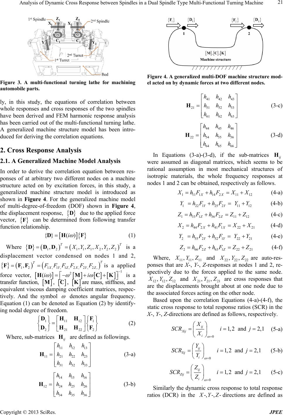 Analysis of Dynamic Cross Response between Spindles in a Dual Spindle Type Multi-Functional Turning Machine Copyright © 2013 SciRes. JPEE Figure 3. A multi-functional turning lathe for machining automobile parts. ly, in this study, the equations of correlation between whole responses and cross responses of the two spindles have been derived and FEM harmonic response analysis has been carried out of the multi-functional turning lath e. A generalized machine structure model has been intro- duced for deriving the correl a tion equations. 2. Cross Response Analysis 2.1. A Generalized Machine Model Analysis In order to derive the correlation equation between res- ponses of at arbitrary two different nodes on a machine structure acted on by excitation forces, in this study, a generalized machine structure model is introduced as shown in Figure 4. For the generalized machine model of multi-degree-of-freedom (DOF) shown in Figure 4, the displacement response, due to the applied force vector, can be determined from following transfer function relationship. (1) Where { }()() 121112 22 ,,, ,,, TT XYZXYZ= =D DD is a displacement vector condensed on nodes 1 and 2, { }() ( ) 1 21,1,1,2,2,2, , T T XYZX Y Z FFFF FF= =F FF is a applied force vector, [][][ ][] 1 2 ()ii ωω ω − =− ++ HM CK is a transfer function, , , are mass, stiffness, and equivalent viscous damping coefficient matrices, respec- tively. And the symbol denotes angular frequency. Equation (1) can be denoted as Equation (2) by identify- ing nodal degree of freedom. 11112 1 22122 2 = DHH F DHH F (2 ) Where, sub-matrices ij are defined as followings. 11 1213 1121 2223 31 3233 hhh hhh hhh = H (3-a) 14 15 16 1224 25 26 34 35 36 hhh hhh hhh = H (3-b) Figure 4. A generalized multi-DOF machine structure mod- el acted on by dynamic forces at two different nodes. 41 4243 2151 5253 61 6263 hhh hhh hhh = H (3 -c) 44 45 46 2254 55 56 64 65 66 hhh hhh hhh = H (3 -d) In Equations (3-a)-(3-d), if the sub-matrices ij H were assumed as diagonal matrices, which seems to be rational assumption in most mechanical structures of isotropic materials, the whole frequency responses at nodes 1 an d 2 c a n be obtaine d, respectively as follows. 111 11421112XX X hFhFXX=+=+ (4-a) 122 12521112 YY YhFhFY Y=+=+ (4-b) 133 13621112ZZ Z hFhFZZ=+=+ (4-c) 244241 12221XX X hFhFXX= +=+ (4-d) 255252 12221 YY YhFhFY Y=+=+ (4-e) 26626312221ZZ Z hFhFZZ=+=+ (4-f) Where, and are auto-res- ponses that are X-, Y-, Z-responses at nodes 1 and 2, re- spectively due to the forces applied to the same node. and are cross responses that are the displacements brought about at one node due to the associated forces acting on the other node. Based upon the correlation Equations (4-a)-(4-f), the static cross respon se to total response ratios (SCR) in the X-, Y-, Z-directions are defined as follows, respectively. 0 1,2 and 2,1 ij Xij i X SCRi j X ω = == = (5-a) 0 1,2 and 2,1 ij Yij i Y SCRi j Y ω = == = (5-b) 0 1,2 and 2,1 ij Zij i Z SCRi j Z ω = == = (5-c) Similarly the dynamic cross res ponse to total response ratios (DCR) in the directions are defined as 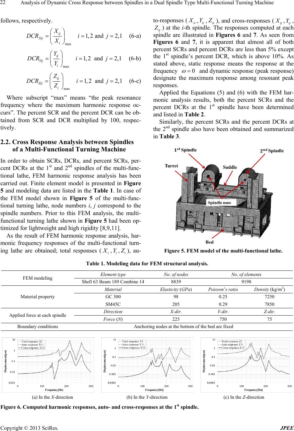 Analysis of Dynamic Cross Response between Spindles in a Dual Spindle Type Multi-Functional Turning Machine Copyright © 2013 SciRes. JPEE follows, respectively. max 1,2 and 2,1 ij Xij i X DCRi j X == = (6-a) max 1,2 and 2,1 ij Yij i Y DCRi j Y == = (6-b) max 1,2 and 2,1 ij Zij i Z DCRi j Z == = (6-c) Where subscript “max” means “the peak resonance frequency where the maximum harmonic response oc- curs”. The percent SCR and the percent DCR can be ob- tained from SCR and DCR multiplied by 100, respec- tively. 2.2. Cross Response Analysis between Spindles of a Multi-Functional Turning Machine In order to obtain SCRs, DCRs, and percent SCRs, per- cent DCRs at the 1st and 2nd spindles of the multi-func- tional lathe, FEM harmonic response analysis has been carried out. Finite element model is presented in Figure 5 and modeling data are listed in the Table 1. In case of the FEM model shown in Figure 5 of the multi-func- tional turning lathe, node numbers i, j correspond to the spindle numbers. Prior to this FEM analysis, the multi- functional turning lathe shown in Figure 5 had been op- timized for lightweight and high rig idity [8,9,11]. As the result of FEM harmonic response analysis, har- monic frequency responses of the multi-functional turn- ing lathe are obtained; total responses ( , , ), au- to-responses (ii X, , ), and cross-responses ( , , ) at the i-th spindle. The responses computed at each spindle are illustrated in Figures 6 and 7. As seen from Figures 6 and 7, it is apparent that almost all of both percent SCRs and percent DCRs are less than 5% except the 1st spindle’s percent DCR, which is above 10%. As stated above, static response means the response at the frequency and dynamic response (peak response) designate the maximum response among resonant peak responses. Applied the Equations (5) and (6) with the FEM har- monic analysis results, both the percent SCRs and the percent DCRs at the 1st spindle have been determined and listed in Table 2. Similarly, the percent SCRs and the percent DCRs at the 2nd spindle also have been obtained and summarized in Table 3. Figure 5. FEM model of the multi-functional lathe. Table 1. Modeling data for FEM structural analysis. FEM modeling Element type No. of nodes No. of elements Shell 63 Beam 189 Combi ne 14 8839 9198 Material property Material Elasticity (GPa) Poisson’s ratio Density (kg/m3) GC 300 98 0.25 7250 SM45C 205 0.29 7850 Applied force at each spindle Direction X-dir. Y-dir. Z-dir. Force (N) 225 750 75 Boundary condit ions Anchori ng nod es at the bottom of the bed are fixed (a) In the X-direction (b) In the Y-direction (c) In the Z-direction Figure 6. Computed harmonic responses, auto- and cross-responses at the 1st spindle. 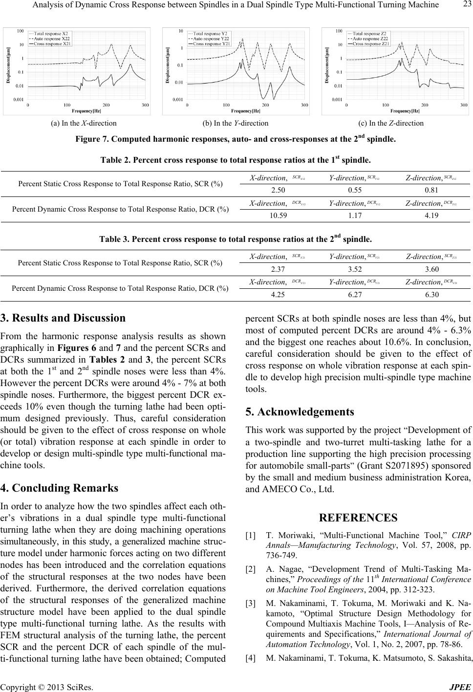 Analysis of Dynamic Cross Response between Spindles in a Dual Spindle Type Multi-Functional Turning Machine Copyright © 2013 SciRes. JPEE (a) In the X-direction (b) In the Y-direction (c) In the Z-direction Figure 7. Computed harmonic responses, auto- and cross-responses at the 2nd spindle. Table 2. Percent cross response to total response ratios at the 1st spindle. Percent Static Cross Response to Total Response Ratio, SCR (%) X-direction, Y-direction, Z-direction, 2.50 0.55 0.81 Percent Dynamic Cross Response to Total Response Ratio, DCR (%) X-direction, Y-direction, Z-direction, 10.59 1.17 4.19 Table 3. Percent cross response to total response ratios at the 2nd spindle. Percent Static Cross Response to Total Response Ratio, SCR (%) X-direction, Y-direction, Z-direction, 2.37 3.52 3.60 Percent Dynamic Cross Response to Total Response Ratio, DCR (%) X-direction, Y-direction, Z-direction, 4.25 6.27 6.30 3. Results and Discussion From the harmonic response analysis results as shown graphically in Figures 6 and 7 and the percent SCRs and DCRs summarized in Tables 2 and 3, the percent SCRs at both the 1st and 2nd spindle noses were less than 4%. However the percent DCRs were around 4% - 7% at both spindle noses. Furthermore, the biggest percent DCR ex- ceeds 10% even though the turning lathe had been opti- mum designed previously. Thus, careful consideration should be given to the effect of cross response on whole (or total) vibration response at each spindle in order to develop or design multi-spindle type multi-functional ma- chine tools. 4. Concluding Remarks In order to analyze how the two spindles affect each oth- er’s vibrations in a dual spindle type multi-functional turning lathe when they are doing machining operations simultaneously, in this study, a generalized machine stru c- ture model under harmonic forces acting on two different nodes has been introduced and the correlation equations of the structural responses at the two nodes have been derived. Furthermore, the derived correlation equations of the structural responses of the generalized machine structure model have been applied to the dual spindle type multi-functional turning lathe. As the results with FEM structural analysis of the turning lathe, the percent SCR and the percent DCR of each spindle of the mul- ti-functional turning lathe have been obtained; Computed percent SCRs at both spindle noses are less than 4%, but most of computed percent DCRs are around 4% - 6.3% and the biggest one reaches about 10.6%. In conclusion, careful consideration should be given to the effect of cross response on whole vibration response at each spin- dle to develop high precision multi-spindle type machine tools. 5. Acknowledgements This work was supported by the project “Development of a two-spindle and two-turret multi-tasking lathe for a production line supporting the high precision processing for automobile small-parts” (Grant S2071895) sponsored by the small and medium business administration Korea, and AMECO Co., Ltd. REFERENCES [1] T. Moriwaki, “Multi-Functional Machine Tool,” CIRP Annals—Manufacturing Technology, Vol. 57, 2008, pp. 736-749. [2] A. Nagae, “Development Trend of Multi-Tasking Ma- chines,” Proceedings of the 11th International Conference on Machine Tool Engineers, 2004, pp. 312-323. [3] M. Nakaminami, T. Tokuma, M. Moriwaki and K. Na- kamoto, “Optimal Structure Design Methodology for Compound Multiaxis Machine Tools, I—Analysis of Re- quirements and Specifications,” International Journal of Automation Technology, Vol. 1, No. 2, 2007, pp. 78-86. [4] M. Nakaminami, T. Tokuma, K. Matsumoto, S. Sakashita,  Analysis of Dynamic Cross Response between Spindles in a Dual Spindle Type Multi-Functional Turning Machine Copyright © 2013 SciRes. JPEE T. Moriwaki and K. Nakamoto, “Optimal Structure De- sign Methodology for Compound Multiaxis Machine Tools; II—Investigation of Basic Structure,” International Journal of Automation Technology, Vol. 1, No. 2, 2007, pp. 87-93. [5] Y. H. Choi, S. H. Jang, H. M. Park, S. J. Jang and J. Y. Cho, “A Genetic Algorithm Based Multi-Step Design Op- timization of a Machine Structure for Minimum Weight and Compliance,” Proceeding of SICE, 2005, pp. 476-481. [6] U. Heisel and M. Gringel, “Machine Tool Design Re- quirements for High-Speed Machining,” Annals of the CIRP, Vol. 45, No. 1, 1996, pp. 389-392. http://dx.doi.org/10.1016/S0007-8506(07)63087-X [7] U. Heisel and A. Feinauer, “Dynamic Influence on Work- piece Quality in High Speed Milling,” Annals of the CIRP, Vol. 48, No. 1, 1999, pp. 321-324. http://dx.doi.org/10.1016/S0007-8506(07)63193-X [8] S. H. Jang, J. H. Oh, H. S. An and Y. H. Choi, “Multi- Objective Structural Optimization of a Pin Turning De- vice by Using Hybrid Optimization Algorithm,” Pro- ceedings of the International Conference of Manufactur- ing Technology Engineers, Seoul, Korea, 2012. p. 73. [9] S. H. Jang, W. Y. Jeong, B. C. Kwon and Y. H. Choi, “A Study on the Static Optimization of Multi-Axis Milling Machine Using TMSA,” Proceedings of KSPE 2009 An- nual Spring Conference, 2009, pp. 227-228. [10] S. H. Jang, Y. H. Choi and J. S. Ha, “A Study on Analysis of Dynamic Compliance of a 5-Axis Multi-tasking Ma- chine Tool by Using F.E.M and Exciter Test,” Transac- tion of the Korean Society of Machine Tool Engineers, Vol. 18, No. 2, 2009, pp. 162-169. [11] Y. H. Choi, J. H. Oh, D. H. Kim, T. Y. Seo and K. H. Kim, “Structural Design Optimization of a 2-Spindle 2- Turret Type Multi-tasking Lathe,” Proceedings of KSME 2013 Annual Spring Conference, Jeju, Korea, 2013, pp. 535-536.
|