Journal of Power and Energy Engineering, 2013, 1, 14-19
http://dx.doi.org/10.4236/jpee.2013.17003 Published Online December 2013 (http://www.scirp.org/journal/jpee)
Copyright © 2013 SciRes. JPEE
Test and Evaluation of Stiffness of a Pin Turning Device
for Large Marine Engine Crankshafts
Y. H. Choi1, G. B. Ha2, D. H. Kim2, H. S. An3
1Department of Mechanical Engineering, Changwon National University, Changwon, Korea; 2Department of Mechanical Design
Engineering, Graduate School of Changwon National University, Changwon, Korea; 3Research Institute, HNK Machine Tool Co.,
Ltd., Haman, Korea.
Email: yhchoi@changwon.ac.kr
Received October 2013
ABSTRACT
In order to prevent unwanted excited vibrations and to secure better machining precision in large size heavy duty ma-
chine tools dynamic stiffness is one of the most desirable and critical properties. In the past decades, many researches
on machine tool stiffness test and evaluation methodology have been made. However any methodology for a Pin Turn-
ing Device (PTD), which is a special kind of turning lathe for machining big size crankshaft pins, is rarely found among
them. This study proposes a test and evaluation process of stiffness of a PTD by measuring frequency response function
at the tool center point (TCP). For conformance proving for the proposed methodology, stiffness of a PTD obtained by
the proposed method with impact hammer test (IHT) has been compared with that determined by FEM.
Keywords: Pin Turning Device (PTD); Machine Tool Stiffness; Compliance Response Function; Impact Hammer Test
1. Introduction
Recently there is an increasing demand for large scale
machine tools for large and precision parts for several
high growth industry fields like; conventional and renew-
able energy power plants, airplane structures, offshore
platforms, ships and marine engines, etc. [1,9,10]. For
large size machine tool, reduced structural stiffness com-
pared to smaller machine tool is one of problems to be
resolved because deflection of a machine structure rises
as an exponential function of its dimension while the al-
lowable deflection in creases linearly [9]. In the past de c-
ades, many researchers have studied machine tool stiff-
ness evaluation methodologies and design optimization
for high structural rigidity and lightweight [2-8]. Ma-
chine tool stiffness evaluation method [3,4] by determin-
ing the compliance frequency response function at TCP
is a more economical and analytical way than that by a
direct cutting test. Thus, this method has been broadly
applied to obtaining machine tool stiffness. Typical stiff-
ness evaluation methodologies for many different types
of machine tools have been studied by M. Weck and K.
Teipel [4] except that for a special purpose lathe like a
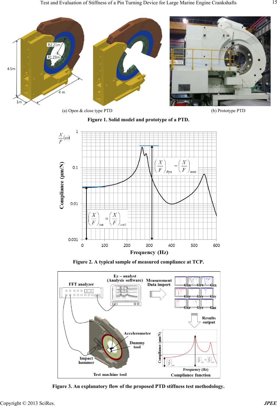
PTD for machining crankshaft pins as shown Figure 1.
The PTD has volum e t ric dimension of
4 14.5××
(
3
m
).
For turning operation of the PTD, a revolving ring
built in tool post rotates around a fixed workpiece dif-
fered from a general lathe, in which a workpiece is rotat-
ing and tool is moved (indexed) by a tool post. The tool
post of the PTD can be indexed in the radial direction
only. Thus cutting forces correspondingly occur in the
radial and tangential directions. Moreover there is a strong
possibility that the PTD does not show uniform stiffness
in the radial and tangential directions along the circum-
ference because the PTD has an asymmetric structure
and open and close type revolving ring as illustrated in
Figure 1. Therefore stiffness in the radial and tangential
directions is a critical inf luential parameter upon dynam-
ic behavior and machining accuracy of the PTD. Thus
this study proposes a proper test and evaluation metho-
dology of stiffness of a PTD.
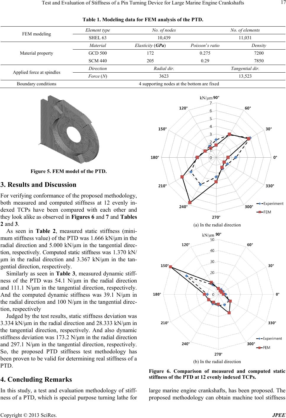
2. Test and Evaluation of a PTD Stiffness
2.1. Test Methodology a nd P rocess
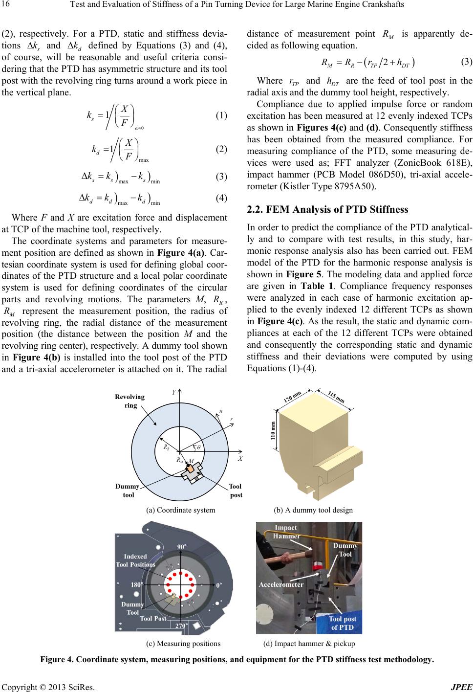
According to M. Weck and K. Teipel [4], stiffness of a
machine tool can be determined from reciprocal of the
compliance measured at TCP as shown in Figure 2.
From the view point of theoretical basis, the PTD stiff-
ness evaluation methodology in this study is almost the
same as theirs [4]. However there is not specified any
method or process for a PTD in [4], so we propose a test
and evaluation methodology of a PTD stiffness as illu-
strated in Figure 3. The static stif fness
s
k
and dynamic
stiffness
d
k
are defined by Equation (1) and Equation
Test and Evaluation of Stiffness of a Pin Turning Device for Large Marine Engine Crankshafts
Copyright © 2013 SciRes. JPEE
15
(a) Open & close type PTD (b) Prototype PTD
Figure 1. Solid model and prototype of a PTD.
Figure 2. A typical sample of measured compliance at TCP.
Figure 3. An explanatory flow of the proposed PTD stiffness test methodology.
Test and Evaluation of Stiffness of a Pin Turning Device for Large Marine Engine Crankshafts
Copyright © 2013 SciRes. JPEE
16
(2), respectively. For a PTD, static and stiffness devia-
tions
and
d
k
defined by Equations (3) and (4),
of course, will be reasonable and useful criteria consi-
dering that the PTD has asymmetric structure and its tool
post with the revolving ring turns around a work piece in
the vertical plane.
0
1
s
X
kF
ω

=

(1 )
max
1
d
X
kF

=

(2)
) )
max min
ss s
kk k∆= −
(3)
) )
max min
dd d
kk k∆= −
(4)
Where F and X are excitation force and displacement
at TCP of the machine tool, respectively.
The coordinate systems and parameters for measure-
ment position are defined as shown in Figure 4(a). Car-
tesian coordinate system is used for defining global coor-
dinates of the PTD structure and a local polar coordinate
system is used for defining coordinates of the circular
parts and revolving motions. The parameters M,
R
R
,
represent the measurement position, the radius of
revolving ring, the radial distance of the measurement
position (the distance between the position M and the
revolving ring center), respectively. A dummy tool shown
in Figure 4( b) is installed into the tool post of the PTD
and a tri-axial accelerometer is attached on it. The radial
distance of measurement point
is apparently de-
cided as following equation.
( )
2
MR TPDT
RRr h=−+
(3)
Where
TP
r
and
are the feed of tool post in the
radial axis and the dummy tool height, respectively.
Compliance due to applied impulse force or random
excitation has been measured at 12 evenly indexed TCPs
as shown in Figures 4(c) and ( d). Consequently stiffness
has been obtained from the measured compliance. For
measuring compliance of the PTD, some measuring de-
vices were used as; FFT analyzer (ZonicBook 618E),
impact hammer (PCB Model 086D50), tri-axial accele-
rometer (Kistler T ype 8795A50).
2.2. FEM Analysis of PTD Stiffness
In order to predict the compliance of the PTD analytical-
ly and to compare with test results, in this study, har-
monic response analysis also has been carried out. FEM
model of the PTD for the harmonic response analysis is
shown in Figure 5. The modeling data and applied force
are given in Table 1. Compliance frequency responses
were analyzed in each case of harmonic excitation ap-
plied to the evenly indexed 12 different TCPs as shown
in Figure 4(c). As the result, th e static and dynamic com-
pliances at each of the 12 different TCPs were obtained
and consequently the corresponding static and dynamic
stiffness and their deviations were computed by using
Equations (1)-(4).
(a) Coordinate system (b) A dummy tool design
(c) Measur ing positions (d) Impact hammer & pickup
Figure 4. Coordinate system, measuring positions, and equipment for the PTD stiffness test methodology.
Test and Evaluation of Stiffness of a Pin Turning Device for Large Marine Engine Crankshafts
Copyright © 2013 SciRes. JPEE
17
Table 1. Modeling data for FEM analysis of the PTD.
FEM modeling Element type No. of nodes No. of elements
SHEL 63 10,439 11,031
Material property
Material Elasticity (GPa) Poissons ratio Density
GCD 500 172 0.275 7200
SCM 440 205 0.29 7850
Applied force at spindles Direction Radial dir. Tangential dir.
Force (N) 3623 13,523
Boundary condit ions 4 supporting nodes a t the bottom are fixed
Figure 5. FEM model of the PTD.
3. Results and Discussion
For verifying conformance of the proposed methodology,
both measured and computed stiffness at 12 evenly in-
dexed TCPs have been compared with each other and
they look alike as observed in Figures 6 and 7 and Tables
2 and 3.
As seen in Table 2, measured static stiffness (mini-
mum stiffness value) of the PTD was 1.666 kN/μm in the
radial direction and 5.000 kN/μm in the tangential dir ec-
tion, respectively. Computed static stiffness was 1.370 kN/
μm in the radial direction and 3.367 kN/μm in the tan-
gential direction, respectively.
Similarly as seen in Table 3, measured dynamic stiff-
ness of the PTD was 54.1 N /μm in the radial direction
and 111.1 N/μm in the tangential direction, respectively.
And the computed dynamic stiffness was 39.1 N/μm in
the radial direction and 100 N/μm in the tangential direc-
tion, respectively
Judged by the test results, static stiff nes s d eviation was
3.334 kN/μm in the radial direction and 28.333 kN/μm in
the tangential direction, respectively. And also dynamic
stiffness deviation was 173.2 N/μm in the radial direction
and 297.1 N/μm in the tangential direction, respectively.
So, the proposed PTD stiffness test methodology has
been proven to be valid for determining real stiffness of a
PTD.
4. Concluding Remarks
In this study, a test and evaluation methodology of stiff-
ness of a PTD, which is special purpose turning lathe for
(a) In the radial direction
(b) In the radial direction
Figure 6. Comparison of measured and computed static
stiffness of the PTD at 12 evenly indexed TCPs.
large marine engine crankshafts, has been proposed. The
proposed methodology can obtain machine tool stiffness
Test and Evaluation of Stiffness of a Pin Turning Device for Large Marine Engine Crankshafts
Copyright © 2013 SciRes. JPEE
18
(a) In the radial direction
(b) In the tangential direction
Figure 7. Comparison of measured and computed dynamic
stiffness of the PTD at 12 evenly indexed TCPs.
Table 2. Comparison of static stiffness of the PTD.
Position (˚)
Static stiffness (kN/μm)
Radial direction Tangential direction
Measured Computed Measu red Computed
0 2.500 1.522 6.666 4.545
30 5.000 4.784 5.000 3.367
60 3.333 3.413 5.000 3.546
90 2.272 1.574 5.000 5.154
120 1.666 1.370 10.000 12.500
150 1.666 1.613 33.333 50.000
180 2.500 2.381 10.000 12.500
210 3.703 5.000 10.000 10.000
240 4.000 6.666 10.000 8.547
270 2.500 3.125 10.000 9.091
300 1.666 1.490 11.111 19.607
330 1.666 1.197 11.111 12.500
Table 3. Comparison of dynamic stiffness of the PTD.
Position (˚)
Dynamic stiffness (N/μm)
Radial direction Tangential direction
Measured Computed Measured Computed
0 69.4 40.7 192.3 185.2
30 93.5 68.0 158.7 113.6
60 133.3 109.9 119.0 100.0
90 78.1 63.7 111.1 116.3
120 61.0 40.3 161.3 169.5
150 64.1 39.5 289.9 476.2
180 120.5 52.6 370.4 476.2
210 163.9 101.0 344.8 270.3
240 227.3 256.4 208.3 243.9
270 144.2 125.0 200.0 256.4
300 54.1 54.3 309.3 434.8
330 57.5 39.1 408.2 588.2
from measured compliance response by impact hammer
test or random excitation test. Following the proposed
method and process, PTD compliance was measured at
12 evenly indexed TCPs and then the corresponding
stiffness was determined. For verifying conformance of
the proposed methodology, measured stiffness has been
compared with FEM analysis results. Thus the proposed
methodology is proven to be appropriate for evaluating
real stiffness of a PTD.
5. Acknowledgements
This work was supported by the Industrial Strategic Tech-
nology Development Program (Grant 10033509) spon-
sored by the Min istry of Tr ade, Industr y and Energy, and
HNK machine tool Co., Ltd.
REFERENCES
[1] L. Uriarte, M. Zatarain, D. Axinte, J. Yague-Fabra, S.
Ihlenfeldt, J. Eguia and A. Olarra, “Machine Tools for
Large Parts,” CIRP AnnalsManufacturing Technology,
Vol. 62, 2013, pp. 731-750.
[2] R. Umbach, “Probl ems of Stiffness and Accuracy of Large
Size Machine Tools,” Proceedings of 6th International
MTDR, 1965, pp. 99-122.
[3] M. Weck, “Handbook of Machine ToolsAutomation of
Controls,” Wiley, 1984.
[4] M. Weck and K. Teipel, (Translated into Korean by J. M.
Lee and K. J. Kim), “Dynamic Characteristics of Machine
ToolTheir Measurement and Evaluation Technology,”
Dae Gwang Mun Hwa Sa Publishing Co., 1985.
[5] D. T.-Y. Huang and J.-J. Lee, “On Obtaining Machine
Tool Stiffness by CAE Techniques,” International Jour-
nal of Machine Tools & Manufacture, Vol. 41, 2001, pp.
1149-1163.
http://dx.doi.org/10.1016/S0890-6955(01)00012-8
[6] M. Arentoft and T. Wanheim,A New Approach to De-
termine Press Stiffness,” CIRP AnnalsManufacturing
Test and Evaluation of Stiffness of a Pin Turning Device for Large Marine Engine Crankshafts
Copyright © 2013 SciRes. JPEE
19
Technology, Vol. 54, No. 1, 2005, pp. 265-268.
[7] M. Arsuaga, R. Lobato, A. Rodrigue and L. N. Lopez de
Lacalle, “Experimental Methodology for Discretization
and Characterization of the Rigidities for Large Compo-
nents Manufacturing Machine,” Procedia Engineering,
Vol. 63, 2013, pp. 623-631.
http://dx.doi.org/10.1016/j.proeng.2013.08.247
[8] S. H. Jang, J. H. Oh, H. S. An and Y. H. Choi, “Multi-
Objective Structural Optimization of a Pin Turning De-
vice by Using Hybrid Optimization Algorithm,” Pro-
ceedings of International Conference of Manufacturing
Technology Engineers, Seoul, Korea, 2012. p. 73.
[9] S. H. Jang, Y. H. Choi, S. T. Kim, H. S. An, H. B. Choi
and J. S. Hong, “Development of Core Technologies of
Multi-Tasking Machine Tools for Machining Highly Pre-
cision Large Parts,” Journal of the KSPE, Vol. 29, No. 2,
2012, pp. 129-138.
[10] H. S. An, Y. J. Cho, Y. H. Choi and D. W. Lee, “Devel-
opment of a Multi-Tasking Machine Tool for Machining
Large Scale Marine Engine Crankshafts and Its Design
Technologies,” Journal of the KSPE, Vol. 29, No. 2, 2012,
pp. 139-146.