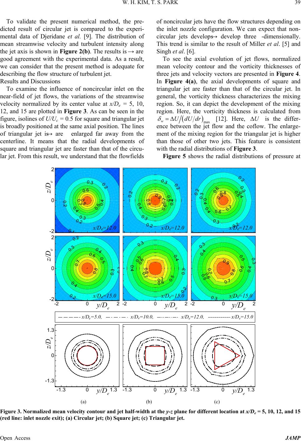
W. H. KIM, T. S. PARK
Open Access JAMP
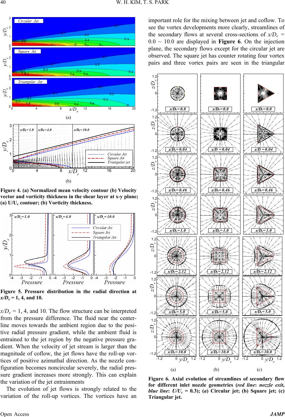
jet. These are driven by the anisotropy of turbulent
stresses. From these results, we can expect that the flow
evolution of the square jet is more three dimensional and
the square jet has a better mixing, because it has many
vortical structures. However, the streamwise velocity of
the triangular jet evo lves much faster. This represents the
weak dependency of the turbulence driven secondary
flows on the enhanced mixing. Also, it is supposed that
the jet mixing strongly depends on the roll-up vortices.
The vortex evolutions are coupled the nozzle configura-
tion, because the inflow has the radial and azimuthal
variati ons due to t he n on -circular cross-section.
As can be seen in the figure, the positive radial mo-
tions are observed in the center region, while the ambient
fluid moves to the center region. As a result, two motions
form a line. The line indicates the interface of secondary
flows between the central jet and ambient coflow. Ac-
cordingly, the interface can be used as a parameter
representing the evolution of jet flows. Near the injection
plane, the interface line nearly coincides with the nozzle
cross-section. As the flow develops down-stream, the
interface line becomes a circle. It is because the vortical
structures are declined gradually and the axial flow
spreads out radially.
On the other hand, the changes of the second ary flows
for the square and triangular jet are faster than that of the
circular jet. From a closer inspection of the figure, we
found that the interface lines nearly correspond to the
location of U/Uc = 0.3 regardless of the nozzle shapes. It
is very interesting to explain the development of jet
flows.
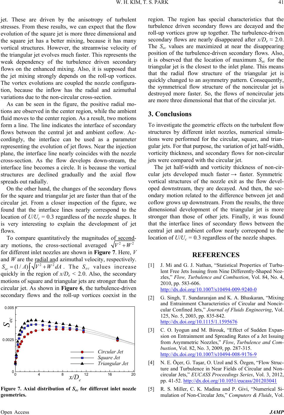
To compare quantitatively the magnitudes of second-
ary motions, the cross-sectional averaged
for different inlet no zzles are shown in Figure 7. Here, V
and W are the radial and azimuthal velocity, respectively.
. The Sec values increase
quickly in the region of x/De < 2.0. Also, the secondary
motions of square and triangular jets are stronger than the
circular jet. As show n in Figure 6, the turbulenc e-driven
secondary flows and the roll-up vortices coexist in the
Figure 7. Axial distribution of Sec for different inlet nozzle
geometries.
region. The region has special characteristics that the
turbulence driven secondary flows are decayed and the
roll-up vortices grow up together. The turbulence-driven
secondary flows are nearly disappeared after x/De ≈ 2.0.
The Sec values are maximized at near the disappearing
position of the turbulence-driven secondary flows. Also,
it is observed that the location of maximum Sec for the
triangular jet is the closest to the inlet plane. This means
that the radial flow structure of the triangular jet is
quickly changed to an asymmetry pattern. Consequently,
the symmetrical flow structure of the noncircular jet is
destroyed more faster. So, the flows of noncircular jets
are more three dimensional that that of the circular jet.
3. Conclusions
To investigate the geometric eff ects on the turbulent flow
structures by different inlet nozzles, numerical simula-
tions were performed for the circular, square, and trian-
gular jets. For th at purpose, the variation of jet half-width,
vorticity thickness, and secondary flows for non-circular
jets were compared with the circular jet.
The jet half-width and vorticity thickness of non-cir-
cular jets developed much faster → faster. Symmetric
vortical structures of the nozzle exit as the flow devel-
oped downstream, they are decayed. And then, the sec-
ondary motion related to the difference between jet and
coflow grows up downstream. From the results, the thr ee
dimensional development of the triangular jet is more
stronger than those of other jets. Finally, it was found
that the interface lines of secondary flows between the
central jet and ambient coflow nearly correspond to the
location of U/Uc = 0.3 regardless of the nozzle shapes.
REFERENCES
[1] J. Mi and G. J. Nathan, “Statistical Properties of Turbu-
lent Free Jets Issuing from Nine Differently-Shaped Noz-
zles,” Flow, Turbulence and Combustion, Vol. 84, No. 4,
2010, pp. 583-606.
http://dx.doi.org/10.1007/s10494-009-9240-0
[2] G. Singh, T. Sundararajan and K. A. Bhaskaran, “Mixing
and Entrainment Characteristics of Circular and Noncir-
cular Confined Jets,” Journal of Fluids Engineering, Vol.
125, No. 5, 2003, pp. 835-842.
http://dx.doi.org/10.1115/1.1595676
[3] C. O. Iyogun and M. Birouk, “Effect of Sudden Expan-
sion on Entrainment and Spreading Rates of a Jet Issui ng
from Asymmetric Nozzles,” Flow, Turbulence and Com-
bustion, Vol. 82, No. 3, 2009, pp. 287-315.
[4] N. E. Öçer, G. Taşar, O. Uzol and S . Özgen, “Flow Struc-
ture and Turbulence in Near Fields of Circular and Non-
circular Jets,” EUCASS Proceedings Series, Vol. 3, 2012,
pp. 41-52.
http://dx.doi.org/10.1007/s10494-008-9176-9
http://dx.doi.org/10.1051/eucass/201203041
[5] R. S. Miller, C. K. Madina and P. Givi, “Numerical Si-
mulation of Non-Circular Jets,” Com puters & Fluids, Vol.
x/D
e
S
ec
04812 16 20
0
0.0025
0.005
CircularJet
Square Jet
Triangular Jet