Journal of Applied Mathematics and Physics, 2013, 1, 26-30
Published Online November 2013 (http://www.scirp.org/journal/jamp)
http://dx.doi.org/10.4236/jamp.2013.16006
Open Access JAMP
A Parallel FEA Computing Kernel for Building Structures
Jin Duan, Yungui Li, Xiao ming Ch en, Hu Qi, Jianyun Sun
China State Construction Technical Center, Beijing, China
Email: duanjin78@126.com, duanjin78@qq.com
Received August 2013
ABSTRACT
With the rapid development of high-rise buildings and long -span structures in the recent years, high performance com-
putation (HPC) is becoming more and more important, sometimes even crucial, for the design and construction of com-
plex building structures. To satisfy the engineering requirements of HPC, a parallel FEA computing kernel, which is
designed typically for the analysis of complex building structures, will be presented and illustrated in this paper. This
kernel program is based on the Intel Math Kernel Library (MKL) and coded by FORTRAN 2008 syntax, which is a
parallel computer language. To improve the capability and efficiency of the computing kernel program, the parallel
concepts of modern FORTRAN, such as elemental procedure, do concurrent, etc., have been applied extensively in
coding and the famous PARDISO solver in MKL has been called to solve the Large-sparse system of linear equations.
The ultimate objective of d eveloping the computing kernel is to make the personal computer have the ability to analysis
large building structures up to ten million degre e of freedoms (DOFs). Up to now, the linear static analysis an d dynamic
analysis have been achieved while the nonlinear analysis, including geometric and material nonlinearity, has not been
finished yet. Therefore, the numerical examples in this paper will be concentrated on demonstrating the validity and
efficiency of the linear analysis and modal analysis for large FE models, while igno ring the verif ication of the nonlinear
analysis capabilities.
Keywords: High Performance Computing; Finite Element Analysis; Building Structure; PARDISO
1. Introduction
With the rapid development of high-rise buildings and
long-span structures in the recent years, high perfor-
mance computation (HPC) is becoming more and more
important, sometimes even crucial, for the structure de-
sign and building construction.
The traditional design softwares, such as PKPM,
ETABS, MIDAS, YJK and so on, can’t match the ad-
vanced requirements of HPC. On the other hand, the
large scale general finite element analysis (FEA) soft-
wares, such as ABAQUS, ANSYS, ADINA, etc., al-
though have the powerful computational abilities, but
they can’t be applied directly to the architectural struc-
ture analysis and design, due to the fact that their pre-
processors are inconvenient for building modeling and
their postprocessors can’t present computational results
according to the building codes in civil engineering.
To satisfy the engineering requirements for HPC, an
integrated simulation system for building structures has
been designed by the authors. This system, which is a
coalition of some secondary software developments toge-
ther with the traditional design softwares and general
FEA softwares, will provide high performance computa-
tion, simulation and technical supports for the design and
construction of the large and complex buildings.
To achieve the above objectives, there are many im-
portant technical indicators to be considered seriously,
typically the following aspects: 1) data transformation
from the structural model to FEA model; 2) parallel FEA
computing kernel developed specially for the building
structures and serving as the supplements to the general
FEA software s.
In this paper, the above mentioned computing kernel
will be presented and discussed using some numerical
examples. This FEA computing program is based on the
Intel Math Kernel Library (MKL) and coded by FOR-
TRAN 2008 syntax, a parallel computer language. To
improve its capability and efficiency, the parallel con-
cepts of modern FORTRAN, such as elemental proce-
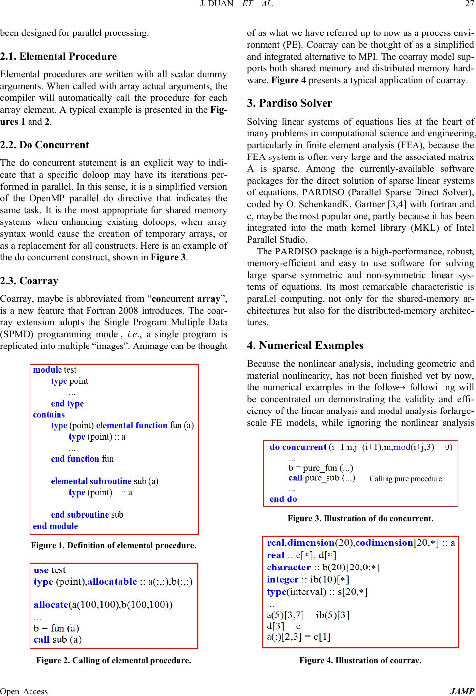
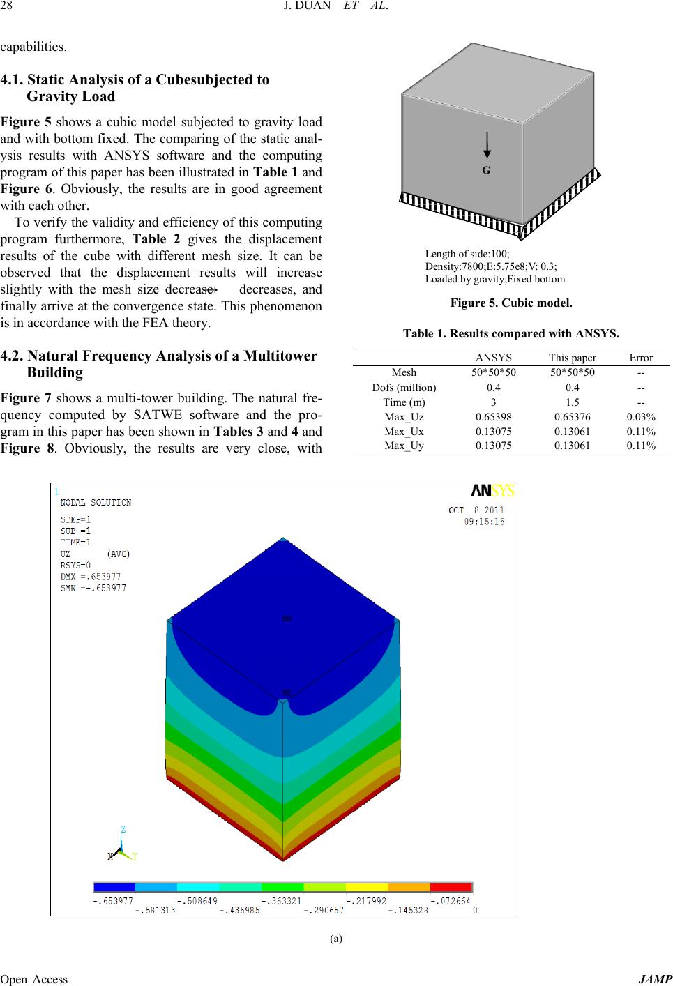
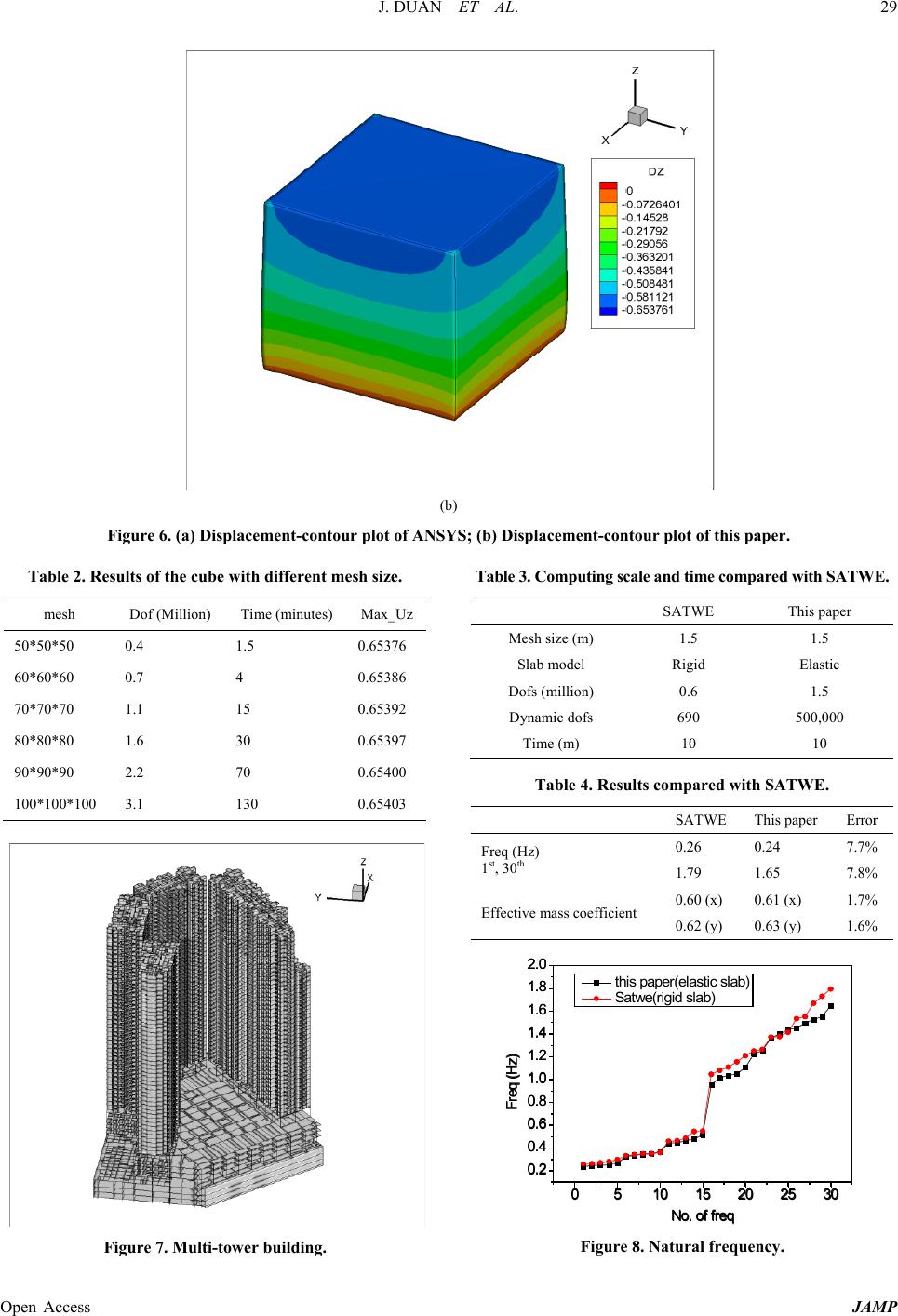
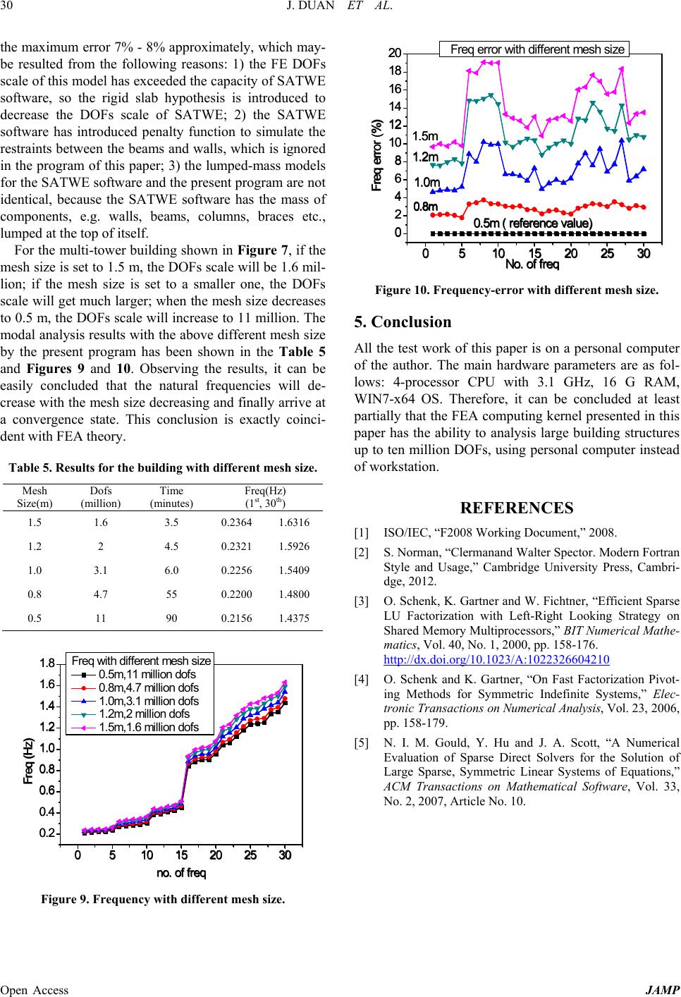
dure, do concurrent, etc., have been applied extensively
in coding. And furthermore, the famous PARDISO solv-
er in MKL will be called to solve the Large-sparse sys-
tem of linear equations.
2. Parallel Syntax in Modern Fortran [1,2]
The modern FORTRAN, i.e. FORTRAN2003/2008, has