M. SURESH ET AL.
52
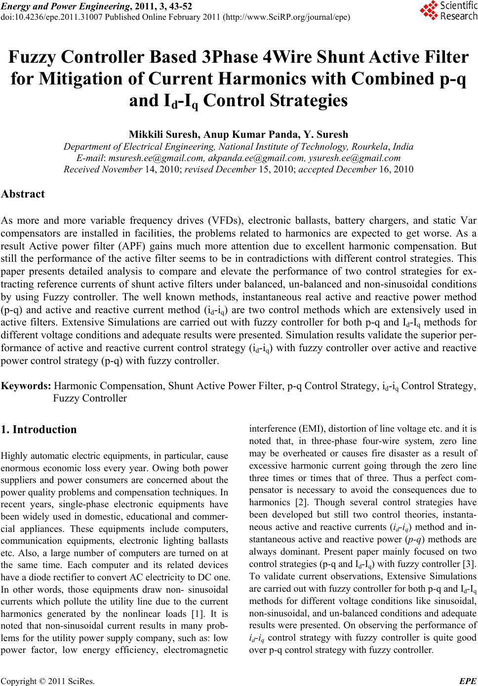
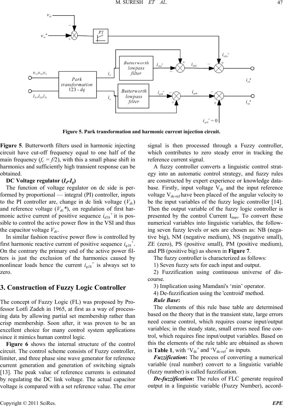
Figure 13. THD for p-q and id-iq methods with fuzzy con
troll
circuit for synchronization so p-q method is frequ
variant, where as in id-iq method angle
‘θ’ is calculated directly from main voltages and
enables the method to be frequency independent. T
large numbers of synchronization problems with un-
balanced and non-sinusoidal voltages are also avoided.
Addition to that DC voltage regulation system valid to be
a stable and steady-state error free system was obtained.
Over all, performance of id-iq theory with fuzzy control-
ler is quite good over p-q theory with fuzzy controller.
6. References
[1] H. Akagi, “New Trends in Active Filters for Power Con-
ditioning,” IEEE Transactions on Industry Applications
Vol. 32, No. 6, November-December 1996, pp. 1312-
1322. doi.:10.1109/28.556633
[2] Z. Peng, G. W. Ott and D. J. Adams, “Harmonic and
Reactive Power Compensation Based on the General
Instantaneous Reactive Power Theory for Three-P
Four-Wire Systems,” IEEE Transactions on Power Elec
tronics, Vol. 13, No. 5, November 1998, pp. 1174-1181.
K. Jain, P. Agrawal and H. O. Gupta, “Fuzzy Logic
Controlled Shunt Active Power Filter for Power Quali
Power Filters in Three-Phase Four-Wire Systems,” IEEE
Transactions on Power Electronics, Vol. 22, No. 1, Janu-
. Aredes, “Instantaneous
o. 5, May 2009, pp. 1350-1363.
0.1109/63.558748
armonics Can-
-
-
er.
ency [9] P. Rodriguez, J. I. Candela, A. Luna, L. Asiminoaei, R.
Teodorescu and F. Blaabjerg, “Current H
thus
hus
cellation in Three-Phase Four-Wire Systems by Using a
Four-Branch Star Filtering Topology,” IEEE Transac-
tions on Power Electronics, Vol. 24, No. 8, August 2009,
pp. 1939-1950.
[10] P. Salmeron and R. S. Herrera, “Distorted and Unbal
,
id
ized
hase
tronics Specialists Conference, Vol. 2, 1997, pp. 1096-
1101.
[13] P. Kirawanich and R. M. O’Connell, “Fuzzy Logic Con-
trol of an Active Power Line Conditioner,” IEEE Trans-
actions on Power Electronics, Vol. 19, No. 6, November
2004, pp. 1574-1585. doi:10.1109/TPEL.2004.836631
-
doi:10.1109/63.728344
[3] S.
ty [1
Improvement,” IEE Proceedings of Electric Power Ap-
plication, Vol. 149, No. 5, September 2002, pp. 317-328.
doi:10.1049/ip-epa:20020511
[4] L. Gyugyi and E. C. Strycula, “Active AC Power Filters,”
IEEE IIAS Annual Meeting, 1976, p. 529.
[5] M. I. M. Montero, E. R. Cadaval and F. B. González,
“Comparison of Control Strategies for Shunt Active
ary 2007, pp. 229-236. doi:10.1109/TPEL.2006.886616
[6] H. Akagi, E. H. Watanabe and M
Power Theory and Applications to Power Conditioning,”
IEEE Press/Wiley-Inter-Science, New Jersey, 2007.
[7] O. Vodyakho and C. C. Mi, “Three-Level Inverter-Based
Shunt Active Power Filter in Three-Phase Three-Wire
and Four-Wire Systems,” IEEE Transactions on Power
Electronics, Vol. 24, N
doi:10.1109/TPEL.2009.2016663
[8] M. Aredes, J. Hafner and K. Heumann,“Three-Phase
Four-Wire Shunt Active Filter Control Strategies,” IEEE
Transactions on Power Electronics, Vol. 12, No. 2,
March 1997, pp. 311-318. doi:1
anced Systems Compensation within Instantaneous Reac-
tive Power Framework,” IEEE Transactions on Power
Delivery, Vol. 21, No. 3, July 2006, pp. 1655-1662. doi:
10.1109/TPWRD.2006.874115
[11] N. G. Jayanti, M. Basu, I. Axente, K. Gaughan and. F.
Conlon, “Development of Laboratory Prototype of a 12
kVA Digital Shunt Active Filter,” Proceedings of 34th
IEEE Industrial Electronics Conference (IECON), Flor-
a, 10th-13th November 2008, pp. 3129-3134.
[12] V. Soares, P. Verdelho and G. Marques, “Active Power
Filter Control Circuit Based on the Instantaneous Active
and Reactive Current i
d-iq Method,” IEEE Power Elec-
4] C. S. Perumalla, P. C. Panda and S. Mishra, “Fuzzy Con-
trolled Harmonic Suppressor and Reactive Volt Ampere
Compensator for Enhancing Power Quality,” 2009 World
Congress on Nature & Biologically Inspired Computing
(NaBIC 2009), Coimbatore, December 2009, pp. 49-54.
doi:10.1109/ NABIC.2009.5393599
Copyright © 2011 SciRes. EPE