Journal of Power and Energy Engineering, 2013, 1, 47-52
http://dx.doi.org/10.4236/jpee.2013.15007 Published Online October 2013 (http://www.scirp.org/journal/jpee)
Copyright © 2013 SciRes. JPEE
47
Retrofit of the Heat Recovery System of a Petroleum
Refinery Using Pinch Analysis
John M. Joe, Ademola M. Rabiu
Department of Chemical Engineering, Cape Peninsula University of Technology, Cape Town 8001, South Africa.
Email: JohnJ@cput.ac.za
Received September 2013
ABSTRACT
Energy efficiency has become an important feature in the design of process plants with the rising cost of energy and the
more stringent environmental regulations being implemented worldwide. In South Africa, as elsewhere, most process
plants built during the era of cheap energy place little emphasis on the need for energy recovery due to the abundance of
cheap utilities sources such as co al. In most of these plants, there exist s ignificant potential for substantial process heat
recovery by conceptual design of the heat recovery system. By maximizing heat recovery from the processes, there will
be a reduction in the process utilities requirement and the associated environmental effects. Pinch analysis has been
demonstrated to be a simple but very effective tool for heat integration and optimization of chemical plants. This study
uses the pinch principle to retrofit the heat exchanger networks (HEN) of the crude distillation unit of an integrated pe-
troleum refinery to evolve a HEN that features optimum energy recovery. The network was further relaxed by trading
off energy cost with capital cost to obtain an optimal HEN topology not too different from the existing network. The
simulation works were implemented in AspenPlus v8.0 environment. Analysis revealed that 34 per cent saving on
energy usage per annum is realizable. This significant saving in energy also results in diminished gaseous pollutants
associated with energy usage.
Keywords: Plant Retrofit; Heat Integration; Crude Distillation Unit; Heat Exchanger Network; Pinch Analysis;
Optimization; Remaining Problem Analysis
1. Introduction
The issues of energy sustainability and security [1] and
the increasingly stringent environmental regulations have
combined to elevate the challenge of energy efficiency to
a high-priority issue [2] for energy intensive industries. It
was reported that the Chinese petroleum refining industry
consumes approximately 15% of industrial fuel oil and
10% of industrial coal [3]. Plants retrofitting towards
cost-effective energy reco ver y and h ence improv ed energy
and utilities usage become attractive and are being im-
plemented worldwide. It has become imperative to im-
prove on the overall economic and environmental foot-
prints of existing plants to enhance their competitiveness
[3] as well as sustainability. The ultimate aim is to syn-
thesize a process that is cost-effective and environmen-
tally benign [4]. It is expected that many process plants
in South Africa have inefficient heat recovery system.
Before the energy crisis, the chemical industries saw lit-
tle use of heat integration to reduce energy usage, since
energy (particularly from fossil fuels) was relatively in-
expensive and abundant [5]. Little emphasis was placed
on optimal process heat recovery because of the cheap
availability of utilities sources at the time of plant con-
struction. The sharp rise in fuel price, dwindling fossil
fuels reserves, and the growing awareness of the envi-
ronmental problems associated with fossil fuels consump-
tion, have however combined to drive the impetus for
design of energy ef ficient pla nt [6]. Ana lyse s of the energy
recovery system of plants design with rule of thumbs have
revealed potential significa nt saving s in utilities usage [7,
8] by placing better matches between the process streams.
A design that maximizes energy recovery using heat ex-
chan ger n et wor ks t o mat ch t he p roc es s hot and cold streams,
will result in minimal external heating and cooling re-
quirements to meet the energy needs of the plant. For
instance, Kemp [9] reported a potential saving of between
30 to 100 per cent in utilities usage in various units of a
petroleum refinery.
This study is motivated by the need to improve on the
energy efficiency of petroleum refineries designed with
rule of thumbs available at the time, by modifying the
existing heat exchanger networks and hence saving on
utilities usage and the emissio n of gre enhouse ga ses from
fossil fuels consumption. The Crude Distillation Unit (CDU)
Retrofit of the Heat Recovery System of a Petroleum Refinery Using Pinch Analysis
Copyright © 2013 SciRes. JPEE
48
[10] consumed the most energy in a refinery, consuming
as much as 2 per cent of the total crude oil processed [11].
It is therefore expected that the use of PT to analyze the
energy recovery system of the CDU will reveal better
matches for process energy transfer, and hence saves on
utilities usage and the associated environmental benefits,
for instance, the emission of obnoxious pollutants. It in-
vestigated the potential saving in utility usage in the crude
distillation unit of a petroleum refinery. A preliminary
energy audit of the plant was carried out using AspenPlus
v8.0 to locate the unit with highest utility requirement
and offers the most potential energy savings. The Re-
maining Problem Analysis (RPA) variant of the Pinch
Technology was applied to locate and reassigned only
the heat exchangers that are inefficiently placed.
2. Process Heat Int eg ration
A design of an efficient and cost effective process heat
recovery system employing series of heat exchangers will
promote efficient utilities usage and requirement leading
to savings in energy cost [12]. The practical importance
of HENs can be found in the fact that most industrial
processes inv olve transfer of heat, either from one process
stream to another process stream or from a utility stream
to a process stream [13,14]. Consequently, the target in
any industrial process design is to maximize the process -
to-process heat recovery and to minimize the utility re-
quirements. To meet this goal, cost-effective HEN con-
sisting of one or more heat exchangers that collectively
satisfy the energy conservation task, is of particular im-
portance.
The use of Pinch Technology (PT) for retrofitting and
grassroot designs, has been found to result in considera-
ble saving for instance in energy usage. This saving di-
rectly improves the economics of the plant. Pinch tech-
nology is one of the least complicated and most effective
technologies for Heat Exchanger Networks (HEN) de-
sign in the energy recovery and optimisation of energy
within the chemical plant. It is based on sound thermo-
dynamic principles without including heavy mathemati-
cal calculations and interpretations. The use of pinch tech-
nology for plant modification is centered on the trade-off
between the savings in utilities versus the cost of the
prop osed c hanges in the plant . The “pinc h ” point represents
the bottleneck of heat recovery. The key concept of pinch
analysis is the setting of energy targets [9] with the aim
to achieve maximum energy saving by maximising process
to process heat recovery and minimising the use of hot
and cold utilities.
3. Methods
3.1. Data Extraction and Energy Target
The design and operating data of the refinery unit were
obtained. A detailed modelling and simulation of the unit
was carried out in AspenPlus v8.0 environment for con-
vergence test to reconcile the streams enthalpy data. The
enthalpy data required were extracted. This was done in
order to scope the existing network for potential energy
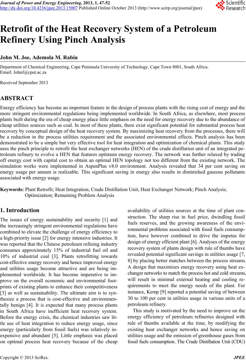
and cost savings. Thermodynamic profiles of the process
streams using the Problem Table algorithms, Composite
Curves and Grand Composite Curves were studied to
determine the targets for the hot and cold utilities and the
position of the pinch. This profile also indicated the
maximum energy recovery possible at the chosen ∆Tmin..
3.2. Maximum Energy Recovery Network Desig n
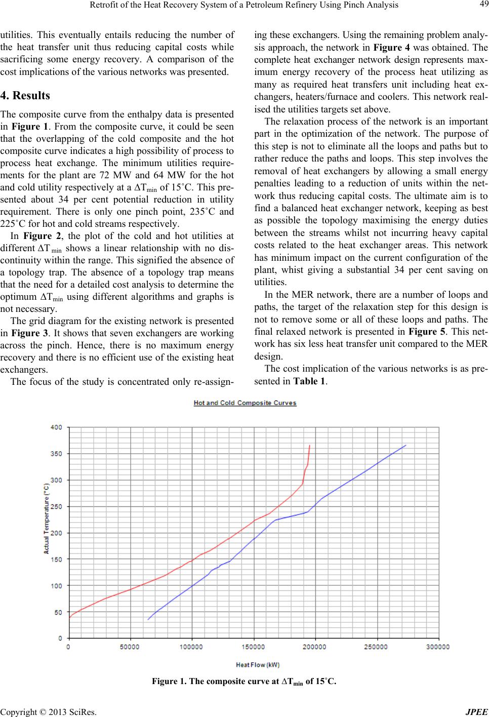
The existence of a topology trap was first investigated by
studying the influence of Tmin on the utilities require-
ment. This is also used to obtain an optimum Tmin for
the retrofitting study.
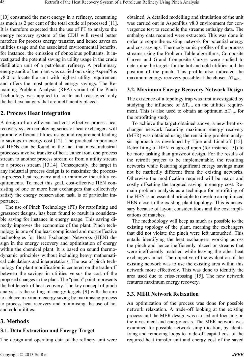
To achieve the target obtained above, a new heat ex-
changer network featuring maximum energy recovery
(MER) was obtained using the remaining problem analy-
sis approach as developed by Tjoe and Linnhoff [15].
Retroffiting of HEN is agreed upon (for instance [5]) to
be more tasking than grassroot design. For the results of
the retrofit project to be implementable, the resulting
networks while featuring significant energy savings must
not be markedly different from the existing networks.
Otherwise the modification required will be major and
costly offsetting the targeted saving in energy cost. Re-
main problem analysis as a technique for retrofitting of
the HEN is an essential principle to develop an optimized
HEN close to the existing plant topology. This is neces-
sary because of layout considerations and the cost impli-
cations of matches.
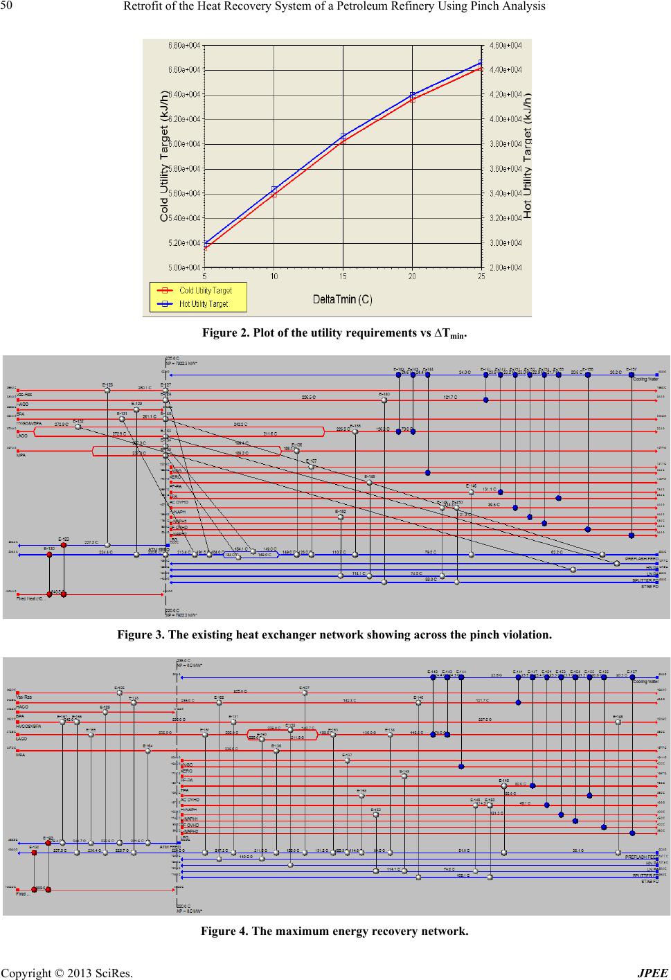
The methodology will keep as much as possible to the
existing topology of the plant, meaning the exchangers
that did not violate the pinch were left untouched. This
entails identifying the heat exchangers working across
the pinch and hence inefficiently placed or streams that
were inefficiently matched while leaving the other heat
exchangers intact. The objective of the evaluation of the
existing network was to use the existing area within this
network more effectively. This was done to identify the
area used due to criss-crossing [15]. The new network
features maximum energy recovery.
3.3. MER Network Relaxation
An optimization of the process was done for possible
network relaxation. A trade-off looking at the existing
process and the MER design was carried out focusing on
the investment and energy costs. The MER network was
examined for possible network simplification, by identi-
fying and removing loops to trade-off capital cost of the
required heat transfer unit and energy cost of the saved
Retrofit of the Heat Recovery System of a Petroleum Refinery Using Pinch Analysis
Copyright © 2013 SciRes. JPEE
49
utilities. This eventually entails reducing the number of
the heat transfer unit thus reducing capital costs while
sacrificing some energy recovery. A comparison of the
cost implications of the various networks was presented.
4. Results
The composite curve from the enthalpy data is presented
in Fig ure 1. From the composite curve, it could be seen
that the overlapping of the cold composite and the hot
composite curve indicates a high possibility of process to
process heat exchange. The minimum utilities require-
ments for the plant are 72 MW and 64 MW for the hot
and cold utility respectively at a Tmin of 15 ˚C. This pre-
sented about 34 per cent potential reduction in utility
requirement. There is only one pinch point, 235˚C and
225˚C for hot and cold streams respectively.
In Figure 2, the plot of the cold and hot utilities at
different ∆T min shows a linear relationship with no dis-
continuity within the range . This signified the absence of
a topology trap. The absence of a topology trap means
that the need for a detailed cost analysis to determine the
optimum Tmin using different algorithms and graphs is
not necessary.
The grid diagram for the existing network is presented
in Figure 3. It shows that seven exchangers are working
across the pinch. Hence, there is no maximum energy
recovery and there is no efficient use of the existing heat
exchangers.
The focus of the study is concentrated only re-assign-
ing these exchangers. Using the remaining problem analy-
sis approach, the network in Figure 4 was obtained. The
complete heat exchanger network design represents max-
imum energy recovery of the process heat utilizing as
many as required heat transfers unit including heat ex-
changers, heaters/furnace and coolers. This network rea l-
ised the utilities targets set abov e.
The relaxation process of the network is an important
part in the optimization of the network. The purpose of
this step is not to eliminate all the lo ops and paths but to
rather reduce the paths and loops. This step involves the
removal of heat exchangers by allowing a small energy
penalties leading to a reduction of units within the net-
work thus reducing capital costs. The ultimate aim is to
find a balanced heat exchanger network, keeping as best
as possible the topology maximising the energy duties
between the streams whilst not incurring heavy capital
costs related to the heat exchanger areas. This network
has minimum impact on the current configuration of the
plant, whist giving a substantial 34 per cent saving on
utilities.
In the MER network, there are a number of loops and
paths, the target of the relaxation step for this design is
not to remove some or all of these loops and paths. The
final relaxed network is presented in Figure 5. This net-
work has six less heat transfer unit compared to the MER
design.
The cost implication of the various networks is as pre-
sented in Table 1.
Figure 1. The composite curve at ∆Tmin of 15˚C.
Retrofit of the Heat Recovery System of a Petroleum Refinery Using Pinch Analysis
Copyright © 2013 SciRes. JPEE
50
Figure 2. Plot of the utility requirements vs ∆Tmin.
Figure 3. The existing heat exchanger network showing across the pinch violation.
Figure 4. The maximum energy recovery network.
Retrofit of the Heat Recovery System of a Petroleum Refinery Using Pinch Analysis
Copyright © 2013 SciRes. JPEE
51
Figure 5. The final relaxed network.
Table 1. Cost comparisons of the heat exchanger networks.
HEN Description Existing HEN MER Network Final Relaxed HEN
Utility Costs ($) 222,536 115,670 149,9 54
Capital Cost (Heat exchangers) ($) 865,045 1,199,490 1,010,176
Capital Cost (Furnace, Coolers) ($) 589,367 542,373 497,866
5. Conclusion
In the current economic climate, with the rising cost of
fuel that provides the industrial plants with their heating
and cooling needs, it has become imperative that the
plant becomes more energy efficient. This study confirmed
that Pinch Techno logy is a very practical, easy a nd intui-
tive method for attaining better process heat integration.
The existing HEN had a number of heat exchangers
working across pinch; these violations were eliminated
during the retrofitting. The final evolved HEN reveal a
potential 34 per cent energy saving in the plant section
studied. A trade-off was explored to find a balance of
utilities usage, number of exchanger units and area. This
was done by using the heat load loops and paths. The
effect of pressure in the evolved HEN network was not
investigated. This must be considered before implement-
ing the recommendations. Alternative methods must also
be used to verify the findings of this study such as math e-
matical optimisation methodologies. In conclusion, pinch
technology is still an important method for evaluating
and scoping for potential energy saving in a chemical
plant. It is particularly relevant today, due to the high
cost of utilities and the adverse environmental impact of
energy usage by industries.
6. Acknowledgements
The authors acknowledge the supports provided by Cape
Peninsula University of Technology, Nigerian National
Petroleum Corporation (NNPC) and the management of
Warri Refinery and Petrochemical Complex, Nigeria.
REFERENCES
[1] D. S. Selvakkumaran and B. Limmeechokchai, “Energy
Security and Co-Benefits of Energy Efficiency Improve-
ment in Three Asian Countries,” Renewable and Sus-
tainable Energy Reviews, Vol. 20, 2013, pp. 491-503.
[2] D. von Hippel, T. Suzuki, J. H. Williams, et al., “Energy
Security and Sustainability in Northeast Asia,” Energy
Policy, Vol. 39, No. 11, 2011, pp. 6719-6730.
http://dx.doi.org/10.1016/j.enpol.2009.07.001
[3] X. Liu, D. Chen, W. Zhang et al., “An Assessment of the
Energy-Saving Potential in China’s Petroleum Refining
Industry from a Technical Perspective,” Energy, Vol. 59,
2013, pp. 38-49.
[4] M. M. El-Halwagi, Chapter 22 Macroscopic Appr oaches
of Process Integration,Sustainable Design through Pro-
cess Integration, Butterworth-Heinemann, Oxford, 2012,
pp. 375-391.
http://dx.doi.org/10.1016/B978-1-85617-744-3.00022-9
[5] Y. Kansha, A. Kishimoto and A. Tsutsumi, “Application
of the Self-Heat Recuperation Technology to Crude Oil
Distillation,” Applied Thermal Engineering, Vol . 43, 2012,
pp. 153-157.
http://dx.doi.org/10.1016/j.applthermaleng.2011.10.022
[6] H. Zhang and G. P. Rangaiah, “One-Step Approach for
Heat Exchanger Network Retrofitting Using Integrated
Differential Evolution,” Computers & Chemical Enginee-
ring, Vol. 50, 2013, pp. 92-104.
http://dx.doi.org/10.1016/j.compchemeng.2012.10.018
[7] M. Escobar and J. O. Trierweiler, “Optimal Heat Ex-
changer Network Synthesis: A Case Study Comparison,”
Applied Thermal Engineering, Vol. 51, No. 1-2, 2013, pp.
801-826.
http://dx.doi.org/10.1016/j.applthermaleng.2012.10.022
Retrofit of the Heat Recovery System of a Petroleum Refinery Using Pinch Analysis
Copyright © 2013 SciRes. JPEE
52
[8] M. Gorji-Bandpy, H. Yahyazadeh-Jelodar and M. Khalili,
“Optimization of Heat Exchanger Network,” Applied
Thermal Engineering, Vol. 31, No. 5, 2011, pp. 779-784.
http://dx.doi.org/10.1016/j.applthermaleng.2010.10.026
[9] I. C. Kemp, Pinch Analysis and Process Integration-A
User Guide on Process Integration for the Efficient Use of
Energy,” Butterworth-Heinemann, 2007.
[10] M. Gadalla, D. Kamel, F. Ashour and H. M. El Din, “A
New Optimisation Based Retrofit Approach for Revamp-
ing an Egyptian Crude Oil Distillation Unit,” Energy
Procedia, Vol. 36, 2013, 2013, pp. 454-464.
[11] M. Errico, G. Tola and M. Mascia, “Energy Saving in a
Crude Distillation Unit by a Preflash Implementation,”
Applied Thermal Engineering, Vol. 29, No. 8-9, 2009, pp.
1642-1647.
http://dx.doi.org/10.1016/j.applthermaleng.2008.07.011
[12] S. Sieniutycz and J. Jeżowski, “12-Heat Integration with-
in Process Integration,Energy Optimization in Process
Systems and Fuel Cells, 2nd Edition, Elsevier, Amster-
dam, 2013, pp. 465-474.
http://dx.doi.org/10.1016/B978-0-08-098221-2.00012-6
[13] P. Rašković and S. Stoiljković, “Pinch Design Method in
the Case of a Limited Number of Process Streams,” Energy,
Vol. 34, No. 5, 2009, pp. 593-612.
http://dx.doi.org/10.1016/j.energy.2008.04.004
[14] S. Sieniutycz and J. Jeżowski, “13-Maximum Heat Re-
covery and Its Consequences for Process System Design,
Energy Optimization in Process Systems and Fuel Cells,
2nd Edition, Elsevier, Amsterdam, 2013, pp. 475-497.
http://dx.doi.org/10.1016/B978-0-08-098221-2.00013-8
[15] T. N. Tjoe and B. Linnhoff, “Using Pinch Technology for
Process Retrofit,” Chemical Engineering, 1986, pp. 47-
60.