Circuits and Systems
Vol.07 No.08(2016), Article ID:67422,12 pages
10.4236/cs.2016.78140
Development of Hybrid MPPT Algorithm for Maximum Power Harvesting under Partial Shading Conditions
Kannabiran Kanimozhi1, Bagarudeen Raja Mohamed Rabi2
1Department of Electrical and Electronics Engineering, ULTRA College of Engineering and Technology for Women, Madurai, India
2Department of Mechanical Engineering, ULTRA College of Engineering and Technology for Women, Madurai, India

Copyright © 2016 by authors and Scientific Research Publishing Inc.
This work is licensed under the Creative Commons Attribution International License (CC BY).
http://creativecommons.org/licenses/by/4.0/


Received 23 March 2016; accepted 20 April 2016; published 16 June 2016
ABSTRACT
In this paper, a Hybrid MPPT algorithm is proposed to improve the efficiency of photovoltaic (PV) systems under partial shading conditions. Partial shading occurs due to clouds, trees, dirt and dust in PV systems. In partial shading, multiple peaks arise in the PV characteristic curve. The Maximum power point tracking (MPPT) algorithm adjusts the duty cycle of the switch in DC-DC converter for regulating the input voltage at the Maximum power point (MPP) and to provide impedance matching i.e. input resistance of converter equal to equivalent solar resistance of PV system at MPP for the maximum power transfer. The Cuk converters have low switching losses and the highest efficiency. Therefore Cuk converter is chosen as power conditioning circuit to track maximum power using Hybrid MPPT technique. The influence of algorithm parameters on system behaviour is investigated and the various advantages and drawbacks of the technique are identified for different weather conditions. Practical results obtained using Solartech SPMO85P PV modules connected to a RL load through Hybrid MPPT controller validates the simulated results.
Keywords:
PV System, DC-DC Converter, Hybrid MPPT Controller, Tracking Efficiency, Partial Shading

1. Introduction
Maximum power is harvested in PV systems by using DC-DC converters as an interface between the PV panel and the load. Although a reliable and fast MPPT algorithm can be designed by using the approaches [1] , its efficiency is strongly affected by various disturbances. The goal of the MPPT is to match the impedance of load to the optimal impedance of PV module [2] .
PV cells connected together form a panel and a number of panels contribute to form a PV array. The PV array consists of a number of panels connected in series and parallel arrangements. The performance of the PV system depends on the operating conditions especially on solar irradiation, temperature, configuration and shading. The shading on PV panel, for instances, due to a passing cloud or neighboring buildings causes not only energy loss in the conversion, but also further non-linearity on the I-V characteristics [3] .
The effect of changing cell temperature and solar irradiance on the choice and design of different topologies of DC-DC converter commonly used in PV systems is discussed in [3] . The changes in irradiation levels during the day affect the array output power which is an expected effect. But unexpected shading effects due to dusts, clouds, leafs, branches of trees and buildings cause shading on cells or part of modules or panels. Under these partial shading conditions, the power versus voltage characteristics of the PV array will contain one global maximum along with many local maxima. The global maxima correspond to maximum power while the others correspond to much lower powers [4] .
Under fluctuation of climatic conditions, MPP changes and MPPT must adjust the converter duty cycle to track the new MPP. Therefore the converter must be chosen to be able to match the MPP under different atmospheric conditions [5] . When the duty cycle changes as a result of changed climatic conditions, the boundary of the converter design parameters will change [6] . So these parameters must be chosen to achieve the highest performance.
Under partial shading conditions, conventional MPPT methods may not be able to track maximum power irrespective of the change in irradiance conditions. At the local maximum power point, it may converge resulting in reduction of PV panel output. Due to this reason the overall PV system efficiency gets degraded. Therefore a Hybrid MPPT algorithm which can be used even under partial shading conditions is discussed in this paper.
The aim of this work is the practical implementation of Cuk DC-DC converters and Hybrid MPPT tracker to improve the PV system performance under partial shading conditions. This work is divided into the following sections: In section 2, PV system specifications and working of Hybrid MPPT controller are discussed. In Section 3 and 4, Cuk converter state space analysis and experimental validation are done. Finally a conclusion is drafted in Section 5.
2. Materials and Methods
Standalone PV systems consist of PV array, DC-DC converters, controllers and load. DC-DC converters are used as an intermediate unit to match the load characteristics with those of the PV array. DC-DC voltage con verter is selected based on the level of voltage required. MPPT algorithm is used for extracting maximum available power from PV module. Maximum power is defined as the peak power voltage at which PV module produces maximum power. Maximum power changes with solar irradiation (G) and temperature (T).
2.1. PV System Modelling
The mathematical model of PV cell shown in Figure 1 consists of a diode representing the PN junction diffusion current. Two resistors (series and shunt) are added for the losses. The unknown parameters of the models are functions of the incident solar irradiation and panel temperature.
The equation of the mathematical model is
 (1)
(1)
where IPV, VPV denote PV cell output current and voltage, Io is dark saturation current. Rse, Rsh denote series and shunt resistance and VT = nKT/q is thermal voltage. Here n is emission coefficient factor of PV cell, K is Boltzmann constant and T is cell temperature.
A PV array (Table 1) is formed with 36 PV cells connected in series and parallel arrangement Individual PV cell has an open circuit voltage Voc = 22.2 V and short circuit current Isc = 5.45 A solar panel is formed from the

Figure 1. Mathematical model of PV cell with one diode.

Table 1. PV Panel specifications.
combination of such modules. A solar array is formed with maximum power of 85.2 W at VMPP = 25.2 V and IMPP = 9.1 A
2.2. Development of Hybrid MPPT Algorithm for Partial Shading Effect
The PV array has nonlinear characteristics. So MPP is tracked using an iterative technique, P&O that involves PV voltage, current and changes in load resistance. MPPT is used to calculate the equivalent duty signal to obtain the maximum output voltage. The conventional P&O algorithm has best performance with load changes, while has poor performance with changes in climatic conditions and partial shading effect.
Under partial shading conditions multiple local maxima will appear on the power-voltage characteristics of solar PV system in that only one will be global maximum power point. The above mentioned situation is shown in the power-voltage curve of partially shaded array in Figure 2. The conventional MPPT methods converge at local maximum power points and the efficiency of the solar PV system reduces considerably.
During partial shading, global and local maximum power points are produced. The, MATLAB analysis in [7] has revealed the ineffectiveness of described conventional MPPT techniques to locate the absolute maximum in P-V graph. Once the local maximum is reached, P&O methods fluctuate around that point. To overcome the issue, an innovative MPPT solution has been developed based on Improved P&O [8] [9] , Incremental Conductance and Fractional Open-Circuit Voltage based MPPT techniques. Fractional Open-Circuit Voltage (FOCV) based MPPT technique utilizes the linear relationship between maximum power point voltage (VMPP) and open circuit voltage (Voc)
 (2)
(2)
k1 is proportionally constant (0.71 - 0.78).
 (3)
(3)
 (4)
(4)
where  is constant Therefore to enhance the performance of conventional P&O algorithm due to climatic changes under constant load (RL), load value (RL) has to be computed in every perturbation step to ensure changes in load and the changes in power as a result of irradiation changes. The load changes (ΔRL) are also considered in the algorithm under constant weather conditions.
Figure 3 shows the flowchart for Hybrid MPPT algorithm. The steps in Hybrid MPPT method are:
1) A sudden decrease or increase of irradiance causes PV system short circuit current to alter. Therefore whenever the current difference sensed is higher than the specified threshold, the MPP is determined by FOCV technique. As k1 determines on the characteristics of the PV array, it is calculated by determining VMPP and VOC for the PV system at various irradiance and temperature levels. Otherwise, difference in the availability of power is calculated.
2) To improve both tracking speed and algorithm accuracy, the variable perturbation size concept has been introduced. As the operation point is closer to the desired point, a smaller perturbation size is produced while the produced perturbation is larger for operation point located far from the absolute MPP. Thus, the energy loss due to the fluctuation of the tracker near MPP is also reduced.
3) During perturbation K suppose that, the solar irradiance is increased under fixed load RL. MPP moves from a lower point to upper point in the I-V curve. Hence voltage perturbation increases.
4) Both increasing of PV power and voltage under constant load from lower to upper I-V and P-V curves will give positive change in power ΔP > 0 where  and positive change in voltage ΔV > 0,
  without change in load resistance. Both positive change in power (ΔP > 0) and voltage (ΔV > 0) under constant load (ΔRL = 0) will orient algorithm to decrement voltage perturbation to obtain new MPP.
5) If solar irradiance is decreased from during next instant of perturbation K + 1 of P&O algorithm voltage level reduces and move the MPP from upper I-V curve to MPP on lower I-V curve. The transferring of operating point will also decrease the PV power under fixed load with negative change in power ΔP < 0, and negative change in voltage ΔV < 0, Both negative change in power (ΔP < 0) and voltage (ΔV < 0) under constant load (ΔRL = 0) will orient algorithm to increment voltage perturbation to reach MPP.
6) When the load is varied under constant weather condition, the conventional P&O algorithm will track MPP of PV system with best performance.
Therefore, the load resistance (RL) will orient the algorithm to recognize the cause of power variation which is either coming from weather or load. The combination of both weather and load change techniques and FOCV, will result in a Hybrid MPPT algorithm. These steps continue till MPP is reached. Thus the voltage at which MPP is reached is tracked.
3. Implementation of Hybrid MPPT Algorithm
The Cuk converter is a converter based on a switching boost-buck topology. Essentially, the converter is composed of two sections, an input stage and an output stage. The schematic of the Cuk converter is presented in

Figure 2. Power vs. voltage characteristics of partially shaded PV system.
Figure 4, where Vin is input voltage source, Vo is output voltage, input inductor L1, controllable switch S, energy transfer capacitor C1, diode D1, filter inductor L2, filter capacitor C2, and load resistance RL. An important advantage of this topology is a continuous current at both the input and the output of the converter due to an inductor in series with both the input and the output of the switch. Unlike the Buck-Boost converter has a discontinuous input current, which adversely affects on the tracking efficiency of the MPP.
The three basic components in MPPT design are: a switch-mode DC-DC converter, a control circuit, and tracking algorithm. The heart of the MPPT hardware is a DC-DC converter. MPPT uses the converter for regulating the input voltage at the MPP and to provide load matching for the maximum power transfer.
During the range of load variation, there is only one point at which the PV module provides its MPP. This point is when RL equal to the resistance at MPP (Ropt) RL = Ropt. But it is very difficult to select a fixed load which matches this value, and even if this is done, this point changes under changed climatic conditions. On the other hand, when a DC-DC converter is connected between the PV module and the load, the operating point depends on the impedance seen by the module (Ri), which depends on two parameters: RL and duty cycle (D). Thus

Figure 3. Hybrid MPPT algorithm.
under different loads, the duty cycle can be adjusted to change Ri to match Ropt at any atmospheric conditions. By changing the duty cycle of the PWM control signal, the load impedance as seen by the source varies and matches the point of the peak power of the source so as to transfer the maximum power to load. Hybrid MPPT algorithm is implemented using Cuk converter as shown in Figure 5.
Cuk Converter Analysis
In the state switch S is on 0 < t < DT the input inductor L1 stores energy from the source over S during the time interval. The energy storage capacitor C1 is now in the right hand mesh and it transfers stored energy, over S, to the load R, and energy storing elements L2 and C2. Due to the inappropriate voltage polarity of the charge on the capacitor C1, diode D1 is reverse biased and therefore off.
When switch S is off, DT < t < T the energy storage capacitor C1 in the left hand mesh is charged through L1 and D in this time interval. Diode D common to both meshes is forward biased in this time interval. L2 and C2 in the right hand mesh transfer their stored energies, left from the previous time interval during the steady-state operation, to the load RL over D again.
In the steady state, the average values of VL1 and VL2 (with the switch duty cycle in range (0 < D < 1) are
 (5)
(5)
 . (6)
. (6)
Since VL2 = VC1 − VC2 when S is on and VL2 = −VC2 when S is off. By letting the both voltages to go to zeros in the steady state, since the voltage across the capacitor cannot change instantaneously when the switching speed is high.

Figure 4. Cuk converter schematic circuit.

Figure 5. Block diagram representation of implementation Hybrid MPPT controller.
 . (7)
. (7)
When a Cuk converter works in CCM it has high efficiency. The choice of circuit elements plays a major role in determining the dynamic characteristics of the converter. Inductor L1 is the minimum value of inductance to guarantee working of DC-DC converter in CCM. Cmin is the minimum value of capacitance to reduce the ripple voltage. Consider Cuk converter works in CCM mode.
In the state space, with the state variables x1, x2, x3 and x4 represented by currents iL1, iL2 and voltages VC1, VC2 the model of Cuk converter can be expressed as follows with  as switching state.
During on state when u = 1 the state space equation can be obtained as
 . (8)
. (8)
During off state when u = 0 the state space equation can be obtained as
 . (9)
. (9)
Using state space averaging technique
 (10)
(10)
 (11)
(11)
where γ is the status of the switches, and  and
and  are the state variables of currents iL1, iL2 and voltages VC1, VC2 and their derivatives, respectively.
The inductor value, required to operate the converter in the CCM is calculated such that the peak inductor current at maximum output power does not exceed the power switch current rating. Taking into account that the ripple of the PV output current must be less than 2% of its mean value, the output capacitor value is calculated.
The input capacitor value is calculated to give the desired peak-to-peak output voltage ripple.
When the Cuk converter is used in PV applications, the input power, voltage and current change continuously with the atmospheric conditions, thus the converter conduction mode changes since it depends on them. Also, the duty cycle is changed continuously in order to track the MPP of the PV array. The choice of the converter switching frequency and the inductor value is a compromise between converter efficiency, cost, power capability and weight. For example, the higher the switching frequency, the lower the inductor core size, but the power switch losses are higher. Also, by using a large value, the peak-to-peak current ripple is smaller, requiring lower current rating power switches, but the converter size is increased substantially because a larger inductor core is required. The value of L1 and L2 decreases with the increase in frequency .The value of C1 and C2 decreases with the increase in frequency. The values of circuit parameters are chosen as follows.
Switching frequency is selected 25 KHz frequency for design as more switching losses occur with higher frequency. The switching frequency must be low enough to keep the efficiency high.
f = 25 K, D = 50%, RL = 10 Ω
 ,
, 
The circuit parameters are calculated and tabulated in Table 2.
4. Results and Discussion
The performance of Cuk converter used as an interface between PV array and load is simulated using MATLAB in this section. The specification of solar panel used is given in Table 1. The efficiency of Hybrid MPPT algorithm is verified by comparing simulation results with conventional P&O algorithm.
4.1. Simulation Results for Two Partially Shaded Series Connected PV Modules
The simulated system is composed of series connected PV module each with 85 W power rating, Hybrid MPPT controller, DC/DC Cuk converter and RL load. The simulations were performed on a Cuk converter circuit with values shown in Table 2. Simulation results are obtained for irradiation changes and changes in load to validate the performance of Hybrid MPPT algorithm.
The simulation model is composed of two Solartech SPM085P solar model with each with a power of 85 watts. The solar irradiance level is stepped from high to low level to check for partial shading. The initial level is set at G = 1000 w/m2. At t = 0.5 sec, the irradiance is suddenly stepped down to G = 500 w/m2. The temperature is kept constant at 25˚C for all irradiance levels. Figure 6 and Figure 7 show the simulation results of extracted maximum power as compared with conventional P&O MPPT controller. The P&O based MPPT controller converges after 300 ms shown in Figure 6 and the power profile changes from 100 w to 90 w. The Hybrid MPPT controller extracts a peak power of 180 w and the power profile changes from 140 w to 130 w. Moreover, the converter’s input power follows the radiation change almost immediately. It is notable that the converter’s input power raises in some 15 ms. It can be seen that, the Hybrid MPPT algorithm is more accurate, powerful and responsive than conventional P&O based MPPT controller. The I-V curves simulated without shading and simulated with shading for P&O MPPT controller are respectively shown in Figure 8. The IV curves for Hybrid
Table 2. Cuk converter parameters.
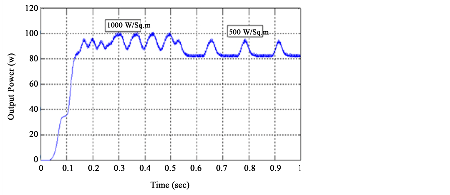
Figure 6. Simulated output power for Cuk converter with conventional P&O MPPT controller for step irradiation.

Figure 7. Simulated output power for Cuk converter with Hybrid MPPT controller for step irradiation.

Figure 8. Simulated IV curve with and without shading with P&O MPPT controller.
MPPT controller shows that global and local MPPs are easily detected (Figure 9).
4.2. Experimental Validation
The experimental set up to test the performance of the proposed MPPT algorithms is shown in Figure 10. The circuit consists of two PV panels, a DC/DC converter, a PIC16F877A microcontroller kit, voltage sensor and current sensor as well as other peripherals for ensuring the robustness of the system. The voltage and current sensors are used to periodically sample the panel’s voltage and current. These sensors are passed to signal conditioning to improve the quality of the signal. Followed by that, these signals are fed into the microcontroller through the analog to digital (A/D) channels.
MPPT is designed using MATLAB for simulations and implemented practically by using a microcontroller that is programmed to execute the Hybrid MPPT algorithm. The program senses the panel voltage (VPV) and current (IPV) to determine the single operating point (IMPP, VMPP) at which maximum power output is produced. The goal of the MPPT is to match the impedance of the load to the optimal impedance of the panel. The algorithm is written using C# programming language on an interface known as Micro C. The program built generates a “.hex” file which is burned onto the microcontroller by means of a lock burner. The output of the microcontroller is the PWM signal to control the Cuk DC/DC converter. The partial shading configuration for two PV panels connected in series for experimental verification with G1 = 1000 W/m2 and G2 = 500 W/m2 is shown in Figure 11.
Figure 12 shows the results of voltage and current under changing solar irradiation levels from 500 watt/m2 to 1000 watt/m2 to create a partial shading effect by hiding PV module. It can be seen that the time taken to reach

Figure 9. Simulated IV curve with and without shading with Hybrid MPPT controller.

Figure 10. Prototype model of Cuk converter with Hybrid MPPT controller.

Figure 11. Partial shading configuration.

Figure 12. PV voltage profile for step irradiation.
MPP is approximately 250 ms, and even if the solar irradiation is changed, the MPP scheme is not giving false results. Also, the experimental and simulation results are almost similar, except the steady state oscillation is invisible in simulation. It is due to the fact that dP/dV is much less.
For a step change in irradiation the voltage changes from first level, open circuit voltage, second level of power tracking and third level of steady state condition as shown in Figure 12. Thus the three-level perturbation is satisfied. A constant output power of 140 W is obtained after 250 ms. A comparison between conventional P&O controller and Hybrid MPPT controller shown in Table 3 validates the performance of Hybrid MPPT controller.
Table 3 shows the effectiveness of the proposed algorithm, resulting in an improvement in the transient response. The tracking time is improved to 130 ms and hence it settles fast. The MPPT tracking efficiency of PV system with Cuk converter is 93.2%. This is a good advantage of proposed P&O MPPT controller when the
Table 3. Comparison between MPPT controllers.
atmospheric conditions change rapidly during partially shaded condition.
5. Conclusion
In discussing the results of the simulation and experiment, a conventional Cuk converter could be a good choice for a standalone PV system that operated in low irradiation conditions. Also, a conventional Cuk converter can be selected if the key consideration is to have a low cost Cuk converter that is a non-complicated circuit to operate and the efficiency and current ripple are not the main priority. The Hybrid MPPT algorithm was simulated using Cuk converter in MATLAB Simulink and experimental prototype was developed using PIC16F877A microcontroller. The Hybrid MPPT algorithm improves steady state stability, dynamic response and tracks the maximum power of 150 Watts with tracking efficiency of 93.2%. Duty ratio control using Hybrid MPPT algorithm offers better energy utilization efficiency and better stability characteristics at a slower transient response and improved performance at rapidly changing irradiance.
Acknowledgements
The author would like to thank the management and Principal of ULTRA College of Engineering and Technology for Women for their continuous support.
Cite this paper
Kannabiran Kanimozhi,Bagarudeen Raja Mohamed Rabi, (2016) Development of Hybrid MPPT Algorithm for Maximum Power Harvesting under Partial Shading Conditions. Circuits and Systems,07,1611-1622. doi: 10.4236/cs.2016.78140
References
- 1. Tajuddin, M.F.N., Arif, M.S., Ayob, S.M. and Salam, Z. (2015) Perturbative Methods for Maximum Power Point Tracking (MPPT) of Photovoltaic (PV) Systems: A Review. International Journal of Energy Research, 39, 1153-1178.
http://dx.doi.org/10.1002/er.3289 - 2. Haroun, R., Aroudi, R.A., Cid-Pastor, A. and Garica, G. (2015) Impedance Matching in Photovoltaic Systems Using Cascaded Boost Converters and Sliding-Mode Control. IEEE Transactions on Power Electronics, 30, 3185-3199.
http://dx.doi.org/10.1109/TPEL.2014.2339134 - 3. Patel, H. and Agarwal, V. (2008) Maximum Power Point Tracking Scheme for PV Systems Operating under Partially Shaded Conditions. IEEE Transactions on Industrial Electronics, 55, 1689-1698.
http://dx.doi.org/10.1109/TIE.2008.917118 - 4. Mastromauro, R.(2012) Control Issues in Single Stage Photovoltaic Systems: MPPT, Current and Voltage Control. IEEE Transactions on Industrial Informatics, 8, 241-254.
http://dx.doi.org/10.1109/TII.2012.2186973 - 5. Woyte, A., Nijsa, J. and Belmansa, R. (2003) Partial Shadowing of Photovoltaic Arrays with Different System Configurations Literature Review and Field Test Results. Solar Energy, 74, 217-225.
http://dx.doi.org/10.1016/S0038-092X(03)00155-5 - 6. Koutroulis, E. (2012) A New Technique for Tracking the Global Maximum Power Point of PV Arrays Operating Under Partial-Shading Conditions. IEEE Journal of Photovoltaics, 2, 1655-1663.
http://dx.doi.org/10.1109/JPHOTOV.2012.2183578 - 7. Kanimozhi, K. and Shunmugalatha, A. (2015) Maximum Peak Power Tracking of Photovoltaic Systems Using Adaptive Sliding Mode Controller. International Journal of Applied Engineering Research, 10, 3073-3078.
- 8. Kanimozhi, K. and Shunmugalatha, A. (2015) Optimal Choice of DC-DC Converter for Enhancement of Power Tracking Efficiency in Photovoltaic System. Proceedings of IEEE International Conference on Computational Intelligence and Computing Research, Vickram College of Engineering, Madurai, Tamilnadu, India, 10-12 December 2015, 816-822.
- 9. Kanimozhi, K. and Shunmugalatha, A. (2016) Photovoltaic Systems with Passive Lossless Cuk Converter Using Hybrid Sliding Mode Control. Journal of Circuits Systems and Computers, 25, Article ID: 1650036(22).