Journal of Electromagnetic Analysis and Applications
Vol.07 No.05(2015), Article ID:56653,9 pages
10.4236/jemaa.2015.75019
A Low Profile Four-Way Directional Antenna with Dual Polarization
Rohani Bakar1, Shumpei Fuse1, Hiroyuki Arai1, Yuki Inoue2, Keizo Cho3
1Department of Electrical and Computer Engineering, Yokohama National University, Yokohama, Japan
2Research Laboratories, NTT DOCOMO INC, Yokosuka, Japan
3Department of Electrical, Electronics and Computer Engineering, Chiba Institute of Technology, Chiba, Japan
Email: harshaz002@yahoo.com, fuse.shumpei@sharp.co.jp, arai@ynu.ac.jp
Copyright © 2015 by authors and Scientific Research Publishing Inc.
This work is licensed under the Creative Commons Attribution International License (CC BY).
http://creativecommons.org/licenses/by/4.0/


Received 24 March 2015; accepted 23 May 2015; published 26 May 2015
ABSTRACT
This paper presents a low profile dual polarized directional antenna composed of loop and dipole arrays mounted on a ground plane with each loops and dipoles being fed independently. Each loop antenna is paired with a reflector while each dipole antenna is paired with a director and a reflector. The proposed antenna is intended for an indoor base station (BS) with resonance frequency of 2.4 GHz and capable of producing four orthogonal directional pattern with downward elevation angle equals to 30˚ and half power bandwidth (HPBW) less than 80˚ in both vertical and horizontal polarization. The reflection characteristics of the loop and dipole arrays are less than −10 dB and the mutual coupling between the vertical and horizontal polarization elements is nearly less than −20 dB. In later progress, the dipole antenna was substituted with printed dipole antenna to achieve a better performance. Both the calculated and measured results demonstrated that the desired radiation patterns were achieved, and the measured results agreed well with the calculated ones. Consequently, a low profile antenna with a thickness of 0.16 λ (20 mm) having the expected radiation pattern is successfully designed.
Keywords:
Directional Antenna, Dual Polarization, Dipole Antenna, Loop Antenna, Reflector

1. Introduction
The communication systems today is facing an ever-increasing demand on providing a wireless system that is the capable of enabling higher voice and data rates while at the same times supporting higher capacity users. Especially for indoor communication systems, various researches regarding channel capacity enhancement were done to oversee this situation [1] - [4] . High channel capacity can be developed using MIMO technology, and a handful of studies on maximizing channel capacity have been reported [5] - [7] . In multi antennas environment, optimizing the radiation pattern and polarization are very effective especially in enhancing the channel capacity. For example, Dietrich et al. [8] empirically demonstrated that a low correlation coefficient was obtained using pattern and polarization diversity. An optimized radiation pattern can be delivered by adjusting the electrical length of parasitic elements of Yagi-Uda thus enhancing channel capacity and improving antenna performance as reported by Honma et al. [9] . In addition, Kyritsi et al. [10] showed that the channel capacity of a hybrid polarization system outperformed a single polarization system due to the independence of the propagation paths of the two polarizations. Qin et al. [11] also reported that the capacity of the system could be improved significantly by using antennas radiating different polarizations compared with antennas with the same polarization.
One of an important design consideration aside from high performance characteristics is miniaturization. A low profile structure is desirable because of easy installation and low costing. However, a notable problem regarding miniaturization of antenna is mutual coupling. As the arrangement of the antenna elements especially the spacing between the elements will be narrow, the mutual coupling between the elements will increase instead. One of the methods to address this issue is by using a matching network [12] . However, this method will cease to unnecessary when we can design an antenna that is small enough in size without reducing the channel capacity by effectively utilizing the polarization [13] - [17] . At the moment however, only few studies have examined miniaturization with consideration of radiation patterns, particularly the design of low profile antenna with directive patterns.
In this paper, we present a novel low profile directional antenna intended for an indoor base station (BS). Although few researches have been reported regarding this topic [13] - [16] , this antenna is designed with an emphasis on radiation pattern instead. And unlike the MIMO antenna that is previously designed considering radiation pattern in [17] , our priority is to produce a more directive pattern in both vertical and horizontal plane. Previously, we have evaluated a BS MIMO antenna mounted on the ceiling for downlink transmission and demonstrated that directive radiation patterns with a tilted angle in downward direction are effective for enhancing signal-to-noise ratio (SNR) and channel capacity compared with a sleeve antenna configuration [18] . The MIMO antenna used in [18] , which 30 mm in height was constructed using cavity-backed slot antenna as vertical element and dipole antenna as horizontal element was proposed in [19] .
Although dual polarization was achieved in [19] , partitions needed to be used inside the cavity in 4 elements adaptation to suppress mutual coupling. In this paper however, we utilize a dipole as the horizontal element and loop antenna as the vertical element with a much lower height of 20 mm. By using a loop, we eliminated the need for cavity and partition and the design became much simpler and with low mutual coupling too. The antenna configuration also was fed independently, which eradicated the need for complex feeding circuit such as phase shifter for example. The design also provides a space in the middle of the structure where we can utilize it according to desirable applications. Although we have already reported this antenna characteristic briefly in [20] , we did not elaborated in details on the process of the structure itself. Therefore, in this paper we explain the process and present the summary of the structure, operation principle and antenna characteristic performance of the proposed antenna.
2. Antenna Design
Channel capacity can be enhanced efficiently by utilizing the radiation pattern and the polarization of designed antenna [9] . In this paper we propose an antenna configuration consists of arrays of loops and dipoles, with operating frequency of 2.4 GHz that gives the lambda, λ equals to 125 mm. The proposed antenna has dual polarization elements, vertical and horizontal with downward elevation angle at 30˚ and half power bandwidth (HPBW) less than 80˚. Each of the arrays will be discuss in details sequently.
2.1. Vertical Polarization Element
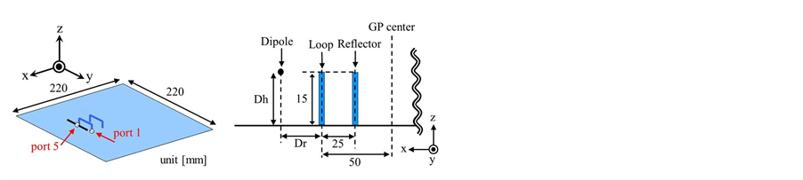
In the initial stage of the research, we designed a single loop with a reflector as shown in Figure 1(a). A loop was mounted on a square ground plane with dimension 220 ´ 220 mm, 55 mm from the edge of one side of the ground plane to make room for other arrays. The height and the length of the loop antenna are 15 mm and 34 mm respectively. The loop structure is actually similar to two monopoles with similar radiation pattern as shown in Figure 1(b), which shows the radiation pattern when the loop was fed without a reflector. But unlike mono-

 (a) (b) (c)
Figure 1. (a) Layout of a single loop antenna with a reflector mounted on a ground plane. Radiation pattern of a single loop antenna in the xz-plane (b) without and (c) with a reflector. V- and H-polarization represent vertical and horizontal polarization respectively.
pole, simply by adding a reflector with the same height to the loop antenna we managed to suppress and shape the radiation pattern into beam-like pattern and tilt it into an angle. From Figure 1(c) we confirmed that not only the pattern has been tilted to 56˚, the HPBW also has been reduced to less than 80˚ with the gain of 8.9 dBi at resonance frequency of 2.4 GHz. The black line in both Figure 1(b) and Figure 1(c) also show that the loop array gives the vertical polarization element to the structure.
Another three pairs of loop and reflector arrays were added and arranged symmetrically to each other as shown in Figure 2(a) produce another 3 additional patterns, realizing 4 beams in vertical polarization in 4 different directions. Each loop was denoted as 1 to 4 indicating their respective ports where they were fed independently but simultaneously. Comparing the result between Figure 1(c) and Figure 2(c), we found similar patterns are obtained where there is only slight difference in performance. Similar results are also obtained for other loop arrays (port 2, 3 and 4) with low mutual coupling at 2.4 GHz between each port as shown in Figure 2(b). From this graph we confirmed that the resonance frequency has increases and mutual coupling became stronger when the identical configurations were arranged in four directions. The reflection characteristic of S11is less than −10 dB at 2.4 GHz, while the mutual coupling S21 and S31 between adjacent and facing elements are less than −30 dB and approximately −20 dB, respectively. The reason for the observed low mutual coupling in Figure 2(b) is due to the suppression of backward radiation in the 270˚ direction by the reflector.
These output performances are able to be maintained simply by adjusting the length of the loop antenna and the distance between this feeding element and the edge of the ground plane to 60 mm, without altering the height of the element. As a result, an antenna of 15 mm in height representing vertical polarization element is achieved. By just adding a reflector, a directional radiation pattern is achieved while at the same time, a lower mutual coupling compared to without reflector is delivered as confirmed in Figure 2(b).
2.2. Combination of Vertical and Horizontal Polarization Elements
Successfully confirming the characteristics of vertical polarization element with desired results, the next following step was to add the horizontal element into the structure to produce dual polarization elements as targeted. This was done initially by extracting just one element of the loop arrays (port 1) from the four arrays shown in Figure 2(a) and added a dipole antenna, denoted as port 5 to serve as horizontal element in the structure as illustrated in Figure 3(a). Combination of dipole antenna and another antenna such as slot or even loop is not exactly a new approach in designing a dual polarization antenna especially when dipole antenna easily deliver good performance with simple configuration as horizontal element. However in this design, the loop and dipole antenna is fed independently to produce dual polarization elements which can be achieve by using just a simple feeding circuit. A distance of Dr was set between the dipole and the loop while adjusting the length of the dipole to match the input impedance at resonance frequency. The reflection characteristic S55 of the dipole as a function of Dh, which represents the height of the dipole from the ground plane are shown in Figure 3(c). As Dh becomes smaller, the resonance frequency shifts to a higher frequency making it more difficult to match the impedance properly. When Dh is greater than 15 mm, which a distance higher than the vertical polarization elements given by the loop array, the performance becomes better where S55 read below-10 dB. From these results we con-
 (a) (b) (c)
Figure 2. (a) Layout of four loop arrays mounted on a ground plane; (b) Reflection characteristics for port 1 and mutual coupling between ports; (c) Radiation pattern for port 1 in xz plane.

 (a) (b) (c)
Figure 3. (a) Layout of a dual-polarized antenna constructed using a loop array (port 1) and a single dipole antenna (port 5) mounted on a ground plane; (b) Two-dimensional view in the yz plane; (c) Reflection characteristics of dipole antenna for each Dh values raging from 5 to 20 mm.
cluded that to obtain a good reflection characteristic, we need to set the dipole at a height of between 18 and 20 mm.
Figure 4 shows the reflection characteristics for the loop and dipole array evaluated at several Dr values ranging from 5 mm to 35 mm, which represents the distance between the loop and dipole antenna at the Dh fixed at 18 mm. This parameter analysis is important to confirm the influence of both vertical and horizontal elements against each other. From Figure 4(a) we confirmed that although the loop antenna has a component parallel to the dipole, the reflection characteristics show that the element resonant at 2.4 GHz regarding the value of Dr and the impedance is matched well below −10 dB. From these results we concluded that the added dipole element only has a very small effect on the loop element. This is one of the important benefits of using dipole as horizontal polarization element aside from simple and easy configuration. With respect to the dipole, the resonance frequency increases and shifted to higher value as the Dr gets smaller. Although the dipole antenna has been influenced a little bit by the loop array, from this parameter analysis we were able to conclude that a Dr greater than 25 mm is preferable where the reflection characteristic read at below −10 dB.
Upon completing the analysis, we proceeded to add other 3 dipoles antennas to the structure in Figure 2(a) to achieve 4 radiation patterns in 4 directions for horizontal element similar to vertical element process before as illustrated in Figure 5. Vertical polarization element is constructed using four loop antenna and reflectors, while four dipole antennas with added directors were used for horizontal polarization element. A dipole without a director gave a half circle untilted pattern that would not satisfy our target. Similar to reflector, a director was added into the structure to change the radiation pattern to the desired angle. A few parameters of the elements were optimized to produces the best performance of this structure. Both the height of the loop and dipole arrays was maintained at 15 mm and 18 mm respectively. The length of the loop antenna and reflector is 35 mm and 40 mm while for dipole antenna and director is 55 mm and 53 mm respectively. Figure 6(a) and Figure 6(b) show the radiation pattern for the loop array and dipole array calculated at port 1 and port 5 respectively. Although both the patterns tilted at the same angle, the HPBW of the dipole is larger and the gain is slightly lower than the loop. From Figure 6(c) also we confirmed that the reflection characteristic for dipole, S55 is higher than −10 dB. From these results we concluded that the HPBW and reflection characteristic of the dipole need to be improved.
 (a) (b)
Figure 4. Reflection characteristic of (a) the loop and (b) dipole arrays for several Dr values.
 (a) (b)
Figure 5. Layout of antenna structure consists of four loops and dipoles arrays in (a) two-dimensional view and (b) three- dimensional view.
 (a) (b) (c)
Figure 6. Radiation patterns of (a) loop and (b) dipole antennas. (c) Reflection characteristics for the antenna configuration.
The results also show that dipole array exhibits a back lobe problem as opposed to radiation pattern for loop array.
When only the feeding element of the dipole was mounted, it radiation pattern forms a half circle shape pointing to z-direction due to the reflection from the ground plane. To obtain obliquely upward beam tilted, we first consider mounting director, which location was optimized by analyzing a few parameters. We confirmed that a director operated well when the distance between a director and a feeding element was 30 mm. For the distance between a feeding element of the dipole and that of loop, more than 25 mm was found to be desirable, as indicated from the results in Figure 4(b). However, to improve the undesirable performance of dipole array, a reflector is added to each dipole array. In consideration of the above results, the director was positioned at the edge of the ground, and the feeding element were positioned 30 mm inside the edge of ground plane. Subsequently, reflector was also mounted to improve the HPBW that is larger than the desired value when we used structure in Figure 5.
Figure 7(a) shows the reflector was positioned 30 mm from the dipole antenna, exactly on the top of the loop antenna. All the parameters for the loop arrays were maintained while the height of the dipole arrays was adjusted to 20 mm to match the impedance properly at 2.4 GHz. The radiation patterns show in Figure 7(b) shows an increasing in cross polarization for the loop although other parameters are maintained. On the other hands, the tilted angle for dipole becomes worse, reading at 79˚ even though the HPBW has improved slightly to 78.8˚ and the gain maxed at 9.1 dBi as show in Figure 7(c). We also confirmed that there is a back lobe problem from the figure. Again, parameters with low elevation angle combining with slightly poor S55 and big back lobe have to be improved to produce a good antenna performance.
After simulating the structure, we were able to decide the working position for the reflector. When the reflector of the dipole antenna was positioned outside the loop antenna, nearer to the edge of the ground plane than the loop antenna, impedance matching is difficult to achieve and unfortunately the tilted angle is larger than the desired value. However, when the reflector was moved and positioned closer to the feeding element of the loop antenna, horizontal polarization is generated in dipole array. Therefore, reflectors of the dipole antennas need to be located inside the feeding elements of the loop antennas, positioned nearer to the center of the ground than the feeding elements of the loop antennas.
Figure 8 shows the optimized configuration of the proposed antenna with 4 arrays of loops and dipoles arranged in 4 directions symmetrically towards each other with port assignments as numbered. The vertical polarization element was constructed with a loop antenna and by adding a reflector, a directional radiation pattern with tilted angle of 60˚ is produced. On the other hand, the horizontal polarization element was constructed using a dipole antenna, a director and a reflector. Similar to loop array, director and reflector are used to shape and direct the radiation pattern into desired results. Each of the parameters of these elements especially the length and the position, was optimized to produce a good antenna performance especially the tilted radiation pattern in both vertical and horizontal polarization. In Figure 8(b), we show that the height of loop arrays was set at 15 mm while the height of dipole arrays was fixed at 20 mm. Furthermore, we illustrate the adjustment of the reflector for the dipole towards the center of the ground plane to optimize the antenna performance.
The added reflector gave benefit to dipole where the reflection characteristic is improved and the back lobe problem is eliminated as shown in Figure 9(b). The distance between the reflector and the loop is just 0.04 λ (5 mm) which is very small as shown in Figure 8(b). Interestingly, the added reflector influenced the performance of the dipole array only, without affecting the performance of the loop array at all considering the small distance between the two. This was achieved because in radiation pattern for the loop array, the null pointed towards z-direction is small enough and not affected by the existence of the reflector.
Figure 9 shows the performance of the optimized antenna structure calculated using port 1 for loop array and port 5 for dipole array. Figure 9(a) and Figure 9(b) show the radiation patterns in the xz plane for both loop and dipole arrays respectively with the radiation patterns tilted at similar angle. For both the loop and dipole arrays, cross polarizations are sufficiently low, and directional radiation patterns with suppressed backward radiation
 (a) (b) (c)
Figure 7. (a) Two-dimensional view of xz plane for added reflector in dipole array. Radiation patterns for (b) loop (port 1) and (c) dipole (port 5) in xz plane.
 (a) (b)
Figure 8. (a) Two-dimensional view of optimized structure of proposed antenna; (b) Reflector position after the adjustment.
 (a) (b) (c)
Figure 9. Radiation patterns of (a) loop array and (b) dipole array. (c) Reflection characteristics of the optimized antenna configuration.
are obtained. The HPBWs for loop and dipole arrays are 57.1˚ and 70.9˚ respectively, while the tilted angles of the beam and gains are 61˚ and 52˚, and 8.4 dBi and 9.1 dBi respectively. The radiation patterns for the other ports also display the same characteristics due to the symmetrical property of the structure.
On the other hand, the reflection characteristics result as illustrated in Figure 9(c) shows that the reflection characteristics for the loop array (S11) and dipole array (S55) are less than −10 dB at 2.4 GHz. Furthermore, the mutual coupling between the vertical and horizontal polarization elements (S51) is less than −30 dB at resonance frequency, which is sufficiently low due to the orthogonal polarization. For the mutual coupling between vertical polarization elements, although S31 is slightly higher than −20 dB, S21 and S41 is less than −30 dB which are sufficiently low as the backward radiation are suppressed by the reflectors of the loop arrays. Table 1 presents the comparison between the loop antenna and dipole antenna to summarize the performance of the proposed optimized configuration.
3. Design Improvement and Measurement Results
In Figure 8 the feeding line structure of the dipole antenna was not considered for simplicity especially when we want to make a prototype out of the design. However, it is necessary to examine a more detailed simulation model to accurately evaluate the antenna performance characteristics. Therefore, in the final stage of the design we replaced the dipole antenna structure which is a straight wire with a printed dipole antenna as illustrated in Figure 10(a). A dipole antenna was printed on both side of a glass epoxy with dielectric substrate of ɛr = 4.8 and a thickness of 1.6 mm. On the ground side of the substrate, the conductor increases in width form 4 to 12 mm forming a tapered shape, functioning as balun as shown in Figure 10(b). The height of the printed dipole antenna was maintained at 20 mm as for dipole antenna.
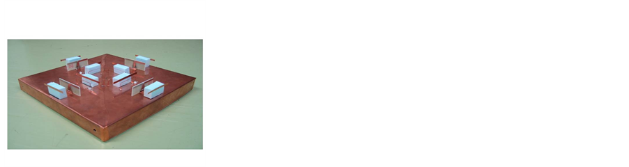
Figure 10(c) shows a fabricated model of the proposed antenna configuration with printed dipole replacing the dipole as horizontal polarization element. The location was as before as shown in Figure 8(a) and the

 (a) (b) (c)
Figure 10. (a) Layout of the final proposed antenna configuration with dipole antenna being replaced with the printed dipole antenna; (b) The front and back view of the printed dipole antenna; (c) Photo of the fabricated antenna design.

Table 1. Performance comparison between loop arrays (port 1) and dipole arrays (port 5).
dimension of each parameter is shown in Figure 10(b). The feeding elements and reflectors for the loop arrays are 1 mm in thickness, while the directors and reflectors for dipole antennas were 4 mm instead. All of the elements were made of perfect conductors, with the height of the loop and dipole arrays were 15 and 20 mm respectively. In the fabricated antenna shown in Figure 10(c), a copper plate was used for the ground plane, loop antennas, directors, and reflectors. All the feeding for both loops and dipoles antenna were conducted by feed pins from beneath the ground. The directors and reflectors of dipole antenna were easily fixed using the styrene foam to make them stay in the designated position and height.
After fabricating the proposed antenna, we measured it for both reflection characteristic and radiation pattern to compare it with calculated results. Figure 11(a) and Figure 11(b) show the comparison of reflection characteristics between the calculated (a) and measured (b) results for the proposed antenna. From these graphs we confirmed that at resonance frequency of 2.4 GHz, both the loop array (S11) and dipole array (S55) readings are below −10 dB in both calculated and measured data. In term of mutual coupling between the vertical and horizontal elements (S51), as expected the measured value is increased considering the feeding structures of the dipole antennas. However, the reading of approximately −20 dB at 2.4 GHz is sufficiently low and acceptable. Moreover, although the mutual coupling between the facing vertical polarization elements (S31) is a little bit higher in the calculated data, we confirmed that all of the isolation characteristics including mutual coupling between the adjacent vertical elements are nearly less than −20 dB in the measured data.
Finally, we compared the calculated and measured radiation patterns in the xz plane for both loop and dipole arrays as shown in Figure 11(c) and Figure 11(d). The above patterns are for calculated results while the below patterns are for measured results. From these results we found that the cross polarizations are sufficiently low and the directional radiation patterns with suppressed backward radiations are obtained. According to the calculation, the tilted angles of the loop and dipole arrays are 61˚ and 52˚ respectively and HPBWs are 55.5˚ and 70.9˚ respectively. Although the calculated radiation patterns are normalized with the maximum value, the gains for the loop and dipole elements are 8.0 dBi and 8.2 dBi respectively. Notably, the measured radiation patterns are similar to the calculated radiation patterns. The tilted angles for the loop and dipole arrays are 63˚ and 50˚ respectively and he HPBW are 61˚ and 78˚ respectively.
As indicated by these results, the desired radiation patterns are achieve based on the design guidelines of 60˚ to 80˚ HPBW and a 60˚ tilted angle, and a low profile directional antenna with a thickness of 0.16 λ (20 mm) has been achieved.
4. Conclusions
We have proposed a low profile dual polarized directional antenna, consisting of loop and dipole arrays for an

 (a) (b) (c) (d)
Figure 11. Reflection characteristics of the (a) calculated and (b) measured proposed antenna. Radiation patterns for (a) loop array (port 1) and (b) dipole array (port 5) with both calculated (above two) and measured (below two) results.
indoor base station. The proposed antenna has four directional radiation patterns in four orthogonal directions in the horizontal plane. A narrow HPBW of approximately 60˚ to 80˚ and a tilted angle from the z-direction close to 60˚ were set as the target parameters of each radiation pattern. Both the calculated and measured results demonstrated that the desired radiation patterns were achieved, and the measured radiation pattern agreed well with the calculated ones. The reflection characteristics of the loop and dipole antennas are less than −10 dB and mutual coupling between vertical polarization elements, and between vertical and horizontal polarization elements is nearly less than −20 dB in the measured data. Consequently, we successfully developed a low-profile directional antenna with a thickness of only 0.16 λ (20 mm).
In this paper, the proposed antenna design is capable of transmitting up to eight beams, and up to four beams with vertical or horizontal polarization depending on the state of the mobile station. In addition, the proposed antenna can be used as a pattern diversity antenna, and vertical and horizontal polarizations can be radiated in the identical directions. Thus, the potential applications of the proposed antenna cover a wide range of possibilities.
References
- Cho, K. and Inoue, Y. (2010) Influence of Cross-Polarization Characteristics on Indoor MIMO Performance Using a Dual-Polarized Base Station Antenna. 2010 IEEE International Symposium on Antennas and Propagation and CNC- USNC/URSI Radio Science Meeting―Leading the Wave, AP-S/URSI 2010.
- Sugimura, D., Arai, M., Sakaguchi, K., Araki, K. and Sotoyama, T. (2011) A Study on Beam Tilt Angle of Base Station Antennas for Base Station Cooperation Systems. IEEE International Symposium on Personal, Indoor and Mobile Radio Communications, PIMRC, Toronto, 11-14 September 2011, 2374-2378. http://dx.doi.org/10.1109/pimrc.2011.6139945
- Wang, P., Wang, H., Ping, L. and Lin, X. (2011) On the Capacity of MIMO Cellular Systems with Base Station Cooperation. IEEE Transactions on Wireless Communications, 10, 3720-3731. http://dx.doi.org/10.1109/TWC.2011.083111.101154
- Arai, H., Abe, K., Takemura, N. and Mitsui, T. (2013) Dual-Polarized Switched Beam Antenna with Variable Phase Shifter. 2013 International Workshop on Antenna Technology (iWAT), 2, 19-22. http://dx.doi.org/10.1109/IWAT.2013.6518289
- Sayeed, A.M. and Raghavan, V. (2007) Maximizing MIMO Capacity in Sparse Multipath with Reconfigurable Antenna Arrays. IEEE Journal of Selected Topics in Signal Processing, 1, 156-166. http://dx.doi.org/10.1109/JSTSP.2007.897057
- Quist, B.T. and Jensen, M.A. (2009) Optimal Antenna Radiation Characteristics for Diversity and MIMO Systems. IEEE Transactions on Antennas and Propagation, 57, 3474-3481. http://dx.doi.org/10.1109/TAP.2009.2026922
- Matthaiou, M., Sayeed, A.M. and Nossek, J.A. (2010) Maximizing LoS MIMO Capacity Using Reconfigurable Antenna Arrays. 2010 International ITG Workshop on Smart Antennas (WSA), Bremen, 23-24 February 2010, 14-19. http://dx.doi.org/10.1109/WSA.2010.5456446
- Dietrich, C.B., Dietze, K., Nealy, J.R. and Stutzman, W.L. (2001) Spatial, Polarization, and Pattern Diversity for Wire- less Handheld Terminals. IEEE Transactions on Antennas and Propagation, 49, 1271-1281. http://dx.doi.org/10.1109/8.947018
- Honma, N., Nishimori, K., Takatori, Y., Ohta, A. and Kubota, S. (2007) Proposal of Compact MIMO Terminal Antenna Employing Yagi-Uda Array with Common Director Elements. IEEE International Symposium on Antennas and Propagation, Honolulu, 9-15 June 2007, 2405-2408.
- Kyritsi, P., Cox, D.C., Valenzuela, R.A. and Wolniansky, P.W. (2002) Effect of Antenna Polarization on the Capacity of a Multiple Element System in an Indoor Environment. IEEE Journal on Selected Areas in Communications, 20, 1227-1239. http://dx.doi.org/10.1109/JSAC.2002.801225
- Qin, P.Y., Guo, Y.J. and Liang, C.H. (2010) Effect of Antenna Polarization Diversity on MIMO System Capacity. IEEE Antennas and Wireless Propagation Letters, 9, 1092-1095. http://dx.doi.org/10.1109/LAWP.2010.2093116
- Wallace, J.W. and Jensen, M.A. (2004) Mutual Coupling in MIMO Wireless Systems: A Rigorous Network Theory Analysis. IEEE Transactions on Wireless Communications, 3, 1317-1325.
- Andrews, M.R., Mitra, P.P. and de Carvalho, R. (2001) Tripling the Capacity of Wireless Communications Using Electromagnetic Polarization. Nature, 409, 316-318. http://dx.doi.org/10.1038/35053015
- Getu, B.N. and Andersen, J.B. (2005) The MIMO Cube―A Compact MIMO Antenna. IEEE Transactions on Wireless Communications, 4, 1136-1141. http://dx.doi.org/10.1109/TWC.2005.846997
- Das, N.K., Inoue, T., Taniguchi, T. and Karasawa, Y. (2004) An Experiment on MIMO System Having Three Orthogonal Polarization Diversity Branches in Multipath-Rich Environment. Proceedings of the 2004 IEEE 60th Vehicular Technology Conference, Los Angeles, 26-29 September 2004, 1528-1532.
- Chiu, C.Y., Yan, J.B. and Murch, R.D. (2007) Compact Three-Port Orthogonally Polarized MIMO Antennas. IEEE Antennas and Wireless Propagation Letters, 6, 619-622. http://dx.doi.org/10.1109/LAWP.2007.913272
- Sarrazin, J., Mahé, Y., Avrillon, S. and Toutain, S. (2008) Investigation on Cavity/Slot Antennas for Diversity and MIMO Systems: The Example of a Three-Port Antenna. IEEE Antennas and Wireless Propagation Letters, 7, 414-417. http://dx.doi.org/10.1109/LAWP.2008.2000830
- Uchida, D., Arai, H., Inoue, Y. and Cho, K. (2010) A Low-Profile Dual-Polarized Directional Antenna for Enhancing Channel Capacity in Indoor MIMO Systems. IEICE Transactions on Communications, E93-B, 2570-2577. http://dx.doi.org/10.1587/transcom.E93.B.2570
- Suyama, A., Uchida, D., Arai, H., Inoue, Y. and Cho, K. (2009) A Dual Polarization 8-Port MIMO Antenna with Dipole and Slot Antennas. IEICE Technical Report, Macao University, Macao, 113-116.
- Uchida, D., Fuse, S., Arai, H., Inoue, Y. and Cho, K. (2010) A Low-Profile Dual-Polarized Directional Antenna for an Indoor MIMO Transmission. Proceedings of the 2010 IEEE Antennas and Propagation Society International Symposium (APSURSI), Toronto, 11-17 July 2010, 1-4.