Journal of Electromagnetic Analysis and Applications
Vol.06 No.13(2014), Article ID:51733,8 pages
10.4236/jemaa.2014.613042
Induction Heating in the Processing of Ti & Zr
Victor Demidovich1, Irina Rastvorova2
1St. Petersburg Electotechnical University (LETI), St. Petersburg, Russia
2National Mineral Resources University (University of Mines), St. Petersburg, Russia
Email: vbdemidovich@mail.ru, rastvorova@mail.ru
Copyright © 2014 by authors and Scientific Research Publishing Inc.
This work is licensed under the Creative Commons Attribution International License (CC BY).
http://creativecommons.org/licenses/by/4.0/


Received 6 September 2014; revised 2 October 2014; accepted 27 October 2014
ABSTRACT
Induction heating has important applications in science and industry. The method of induction heating can be successfully used for melting and heat treatment of titanium and zirconium alloys. Different applications using induction precise heating before plastic deformation are discussed in this paper. For alloys of many metals such as titanium, zirconium, niobium, tantalum, etc., it is important to provide precision heating with a high degree of homogeneity of the temperature field and strict adherence to the condition of heating. This is explained by polymorphism of the alloys based on these metals, their chemical activity at high temperatures and the specific thermal and electrical properties. It is very important for induction heating to define the extreme achievable unevenness of the temperature field. For special alloys it is necessary to use resistance furnaces for homogenization of billets’ temperature after heating in the inductors. Optimal control can be used for massive billets to reduce significantly the heating time, energy expenses and to improve the quality of the temperature field distribution. Optimization of induction heating process can be achieved by synchronous solution of the problem of optimal control and design with specially developed models.
Keywords:
Induction Heating, Optimal Control, The Method of Electromagnetic Processing, Electromagnetic Numerical Analysis, Precise Heating, Melting and Heat Treatment of Titanium and Zirconium Alloys

1. Introduction
Technologies of induction heating find wide application not only for the now traditional heat treatment of steel, aluminum, copper, but also for heating of the titanium and zirconium alloys. Induction installations are widely applied for heating billets and slabs before rolling, reduction, straightening, and other types of plastic deformation. The implementation of induction heating in the processing line of titanium billets is explained by the following well-known advantages: good energy characteristics, a high heating rate, simple control, the possibility of complete automation, small unit dimensions, and easy maintenance (including the case of changes in the size of billet) [1] .
For many alloys of metals such as titanium, zirconium, niobium, tantalum, and some others, it is important to ensure the accuracy of heating with a high degree of homogeneity. This is explained by polymorphism of these alloys and narrow temperature range where high quality plastic deformation can be realized. Low thermal conductivity and high temperature losses at the surface result in maximum temperature inside of the billet that could not be measured by pyrometers. At the same time precise heating with very high homogeneity of the temperature field and strong execution of the temperature profile during the heating time are essential for thermal processing of these alloys before plastic deformation. Therefore, it is very important for induction heating to determine the maximum achievable uneven temperature field under real conditions of heating. In the case of critical components, when the plastic deformation takes place in a very narrow temperature range (±5˚C - 10˚C), it is often used thermostats after heating in the inductor. Nevertheless the precise induction heating could be realized in the stage heater.
2. Specifics of Heating Non-Ferrous Alloy Billets by Induction Method
Heating of Ti & Zr alloys has features associated with the physical and chemical properties of the material and with high demands of consumers for quality products in accordance with international and national standards in aviation industry.
Requirements for heating billets from non-ferrous alloys:
・ formation of an extremely possible uniform temperature field along the length and cross section of the billet;
・ exclusion of overheating the billet;
・ minimizing the heating time.
Due to the skin effect in the billets during induction heating heat sources are distributed over the cross section of the billet non-uniformly: the maximum of heat sources are at the surface and the intensity of the heat sources is reduced with increasing distance from the surface.
Accordingly, the surface layers have a higher temperature than the inner, and this temperature difference is greater, the greater the power of heating and the higher frequency of current. Heat losses from the outer surface qualitatively affect the nature of the temperature field in the cross section of the billet: due to heat losses from the surface the zone is formed in deep of the billet which has a higher temperature than the surface. This phenomenon is taken place during induction heating of metals, but for titanium alloys, it appears very bright because of the low thermal conductivity and high heat losses. Overheating of the inner layers of metal may lead to local changes in the structure of metal, to the appearance of residual stresses, and at high heating temperatures― to melt the internal layers. The technology of melting Ti inside of the billet is under investigation [2] .
The typical temperature distribution in the cylindrical billet heated by induction method is illustrated in Figure 1. During time t1 surface temperature with a high power of heating is considerably higher than the temperature at the center. Further power of induction heating decreases and the temperature difference between the surface and the centre is decreased too.
Due to heat losses from the surface maximum temperature during induction heating every time is located inside (Figure 1). At the heating time t2 when the temperatures at the surface and in the center are equal, the temperature difference ΔT2 = εinf is the value that could not be less under this conditions of heating. The temperature difference ΔT2 = εinf depends on final temperature of heating, diameter of billet, frequency of current, thermal conductivity of alloy, heat losses from the surface (quality of refractory).
Two types of refractory were reviewed, which provide in stationary mode heating heat losses from the surface of the billet with coefficient of heat transfer α = 0.002 W/(sm2 ˚C) and α = 0.006 W/(sm2 ˚C). Actual refractory that currently can be installed in the induction heaters provide conditions of heat losses lying in the specified range.
For the comparison calculations of heating cylindrical titanium billets from alloy VT6 and diameter 120 mm in inductor were done. Simulations of heating billets were done at frequencies 500 Hz and 1000 Hz up to final temperature of heating 750˚C (Figure 2). Both options were calculated for the coefficients heat transfer α = 0.002 - 0.006 W/(cm2 ˚C). Specific power was chosen in such a way that at the end of the heating surface temperature and the temperature in the center were identical and equal.
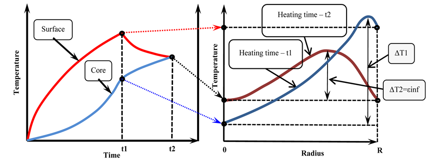
Figure 1. Typical distribution of temperature field during induction heating.
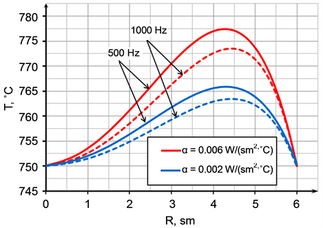
Figure 2. Temperature distribution in the titanium billet.
Figure 2 shows the temperature distribution in the titanium billet at the end of the heating. For low-tempe- rature heating (700˚C - 800˚C) and small (<120 mm) diameters it is possible implementation of high-precision heating ±15˚C (Figure 2). The Figure 2 shows that the increase in frequency reduces the temperature difference. Low frequency and bad refractory result in the lower quality of heating titanium billets.
Figure 3 shows the lowest temperature difference εinf that could be achieved by induction heating titanium billets with different diameters for different final temperatures. The more diameter and higher final temperature the more limit temperature difference εinf. These data were received by using only radial temperature distribution. In fact it is necessary to take into account real length of billets and inductors and to use 2D model.
In this case lowest temperature difference εinf could be much higher and depends additionally on value σ (Figure 4).
Figure 4 shows the dependence of lowest temperature difference εinf from the difference between length of inductor and billet σ in the stage induction heater. Power distribution along the billet strongly depends on this value σ. There is optimal σ when the temperature difference εinf in the volume of billet is minimal. This occur in the case of equality of the temperature values at three points Тs = Тc = ТЗ, где Тs―temperature in the middle of the billet on its surface, Тc―temperature in the middle of the billets on its axis, ТЗ―the temperature at the end of the billet. Tmax is a maximum temperature inside of the billet. These data were received for zirconium billet with diameter of 275 mm by using 2D-model with and without thermal refractors at the edges of inductor. The final temperature of heating is 900˚C. Thus we can see that if you do not take into account the heat losses from the ends of the billet (heat losses from the ends of the billet are small with refractory at the ends of inductor), the value of εinf in 1D and 2D models are similar at the optimal σ.
Maximum temperature Tmax is located at a certain depth from the surface and depending on the degree of end effect can change the coordinates on the length of the billet. In most real induction devices end effects of the
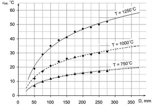
Figure 3. Lowest temperature difference εinf (maximum achievable uneven temperature field) vs. diameter at different final temperatures (1D-problem).
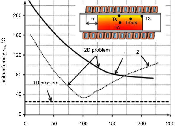
Figure 4. Maximum achievable uneven temperature field vs σ without (1) and with thermal refractory at the edges of inductor (2).
inductor and the billets are superimposed on each other and with a small length of the heated product or winding are also the imposition of distortions arising from both ends of the elements of the system.
To achieve the maximum allowable distribution of temperature field along the diameter and length of the billet different methods of optimal control are used during heating. These include the choice of frequency, the choice of the necessary power and heating time, passive and active spatial means of regulation.
The most known electrical means of temperature regulation are: using end effect of inductor and billet, the Faraday rings, additional inductors at the ends of coil, concentrators, etc. This means influences on the power distribution along length of billet and properly on the temperature field. To obtain a more uniform temperature field in the case of multi-layer coil it can be used different coil winding step on the outer layers of the heater. At the ends of the inductor denser winding is used. In this case, the power is fed more in the ends of the billet, which contributes to the heating. In some cases, such as when one coil is used for heating billets of different lengths sites with more dense and winding sections with less dense winding are symmetrically alternated on both sides of the inductor, thus provides a relatively uniform heating along the length of the billet.
When we heat solid cylindrical billets, flat heater can be installed in the end of the inductor. To control the temperature distribution power supply of the butt heater can be carried by either AC voltage, taken from the primary coil, either DC or AC voltages of any frequency. Power supply of the butt heater can be carried by electromagnetic coupling with an additional inductor winding, ends of which are attached to both ends of the resistive heater. Additional inductor may have an independent power source. The thermal compensators can be implemented in the form of closed rings from heat-resistant conductive material and can be installed inside the inductor at the end zones of the lining. During heating simultaneously with the main coil, they create a heat shield, thereby reducing heat losses from the face side billet.
3. Case Story: Precise Heating of the Zirconium Billet in a Stage Induction Heater
For heating billets of various length in one inductor, it is necessary to supply it with different methods of optimal control of billet’s temperature field. As a variant for change of flooring current density in butt-end areas of billet it is possible to use the two-layer inductor which inside layer is made with constant step of coil winding, and external has ruptures. Three areas of coil winding are thus formed: the central area and two outer, arranged symmetrically about the inductor’s center. The length of ruptures gets out such that the billet’s length with the minimum length was equal to length of the central area, and butt-end of billets with the maximum length coincided with edges of outer areas.
Thanks to such ruptures’ arrangement of the coil’s second layer distribution of current density flooring on billet’s length so that to reduce influence of inductor’s and billet’s edge effect at change of billet’s length is made.
The heating quality depends on the billet’s length. In case of short billet heating completely is provided with the coil winding of central area. For long billet the coil winding of central area provides heating only a regular zone. Heating the end zone is due to the outer areas of the coil winding of the second coil’s layer. Such design of an inductor is characterized by that the average detail’s part has the greatest temperature, and it excludes overheating and possible fusion of billet on some distance from its surface.
Figure 5 shows the distribution of final temperature field of zirconium billet with a diameter 220 mm and a length of 475 mm after induction stage heating. Final temperature is 1000˚C. It is necessary to ensure the maximum allowable accuracy of heating ±20˚C. This is achieved through the usage of optimal regime of heating, choice of optimal design of the stage induction heaters and the usage of different spatial controls temperature field means.
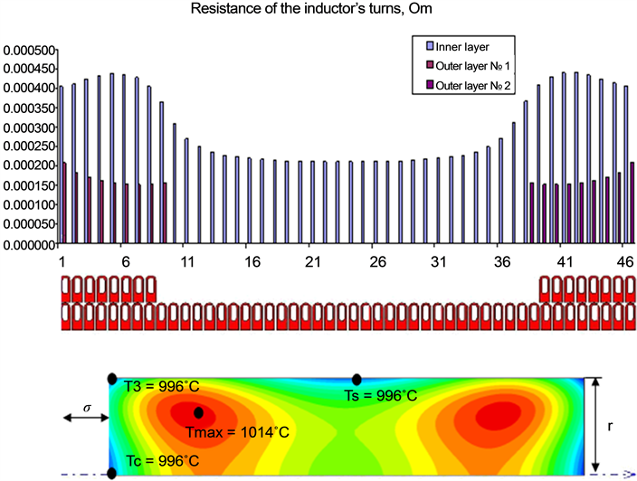
Figure 5. Resistance of the inductor’s turns and final temperature distribution in the billet.
The induction heater is a two-layer coil with a refractory to reduce heat losses from its surface. Heat shields are installed on the ends of the inductor to reduce heat losses by radiation from the ends of the billet. The second layer of the inductor consists of several symmetrically located relative to the center of turns at each end of the coil. This allows enhancing electromagnetic field at the ends of the inductor to compensate for end effects.
Heating is carried out in two stages. The first stage is accelerated heating of billets with a maximum power at 60 Hz, and then the mode of thermostatic is activated at minimum capacity to equalize the temperature field and compensate heat losses from the surface of the billet. Thus it is possible to achieve the desired heating temperature 1000˚C with a specified accuracy of ±10˚C (Figure 2).
As can be seen from the Figure 5, the absolutely homogeneous distribution of temperature field cannot be reached, but we can maintain the utmost attainable unevenness temperature distribution for a given billet in the desired range, as well as the difference between the temperatures Ts, Tc and T3 is minimal [3] .
Furthermore, using modern software package UNIVERSAL, make it possible to simulate not only the temperature field distribution along the length and cross section of the billet, but also display the values of resistance in the turns of the inductor, which contributes to greater accuracy in the model of induction heater [3] .
Distribution of the resistance of the inductor’s turns in different layers is presented in Figure 5.
Coils’ resistance of the outer layer is lower than the resistance of turn’s inner one, which explains the ring and proximity effects. Coils’ resistance inner layer, located opposite the turns of the outer layer, increases, which is also explained by the redistribution of current over the cross sections of turns.
4. Precise Induction Heating of Long Ti Billets
The method of induction heating of long billets subjected to oscillating motion in several induction heaters can be an alternative to heating a billet in one induction heater, where the billet motion along the guides is often difficult because of a large billet weight or length. In this case, a billet moves continuously and periodically changes the motion direction to the opposite one [4] . A billet is heated in several induction heaters spaced apart along one axis. Rollers are placed between the induction heaters for easy billet motion, and the billet oscillates in the induction heater zone at certain amplitude [5] (Figure 6).
Reduction of an induction heater’s dimensions s achieved by using heating of long-length titanium billets with the organization of the oscillating motion in several inductors. The given heating way is characterized by following advantages:
・ convenience of billet’s moving in a heater, including loading and an unloading;
・ rather small heater’s sizes;
・ independence of billet’s heating rate of a following technological process’ speed;
・ maintenance of the maximum achievable uneven temperature field, realization of the precise induction heating;
・ possibility of heating in protective atmosphere.
For this purpose was developed and implemented a precise heating system of long billets of titanium alloys by induction method.
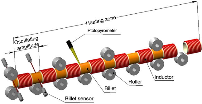
Figure 6. Schematic diagram of an induction oscillating furnace.
System of induction heating, consisting of eight identical inductors length 530 mm, mounted on one axis and equidistant from each other equal to 340 mm, was developed. There are rollers 100 mm in diameter to move the workpiece between the inductors. Billet does oscillating motion in the area of the inductors with amplitude of 870 mm (Figure 6).
For the case of heating with oscillating motion, the temperature field distribution along the billet length has a wavelike character with a certain period. To measure the temperature distribution along and across the billet, it is sufficient to measure the temperature drop at three or four points in a small segment equal to the oscillating amplitude.
Based on numerical simulations the scheme of thermocouples’ installation for an estimation of non-unifor- mity of heating has been developed (Figure 7).
Thermocouples t1, t4, t6, t8 have been established in the billet on depth 50 mm, t2, t5, t7―on depth 10 mm, t3―on depth 5 mm. In the beginning of the heating process the thermocouple t3, t4 and t5 settled down in the distance center between inductors. The thermocouple t8 is necessary for an estimation of influence of edge effects on a detail end face.
The measured temperature nonuniformity along and across the billet is within 20˚C.
5. Utilization of Induction Heaters in Line with Resistance Furnaces
For special alloys it is necessary to rich temperature field of billets or slabs with deviation not more than ±5˚C at the level of temperature 1000˚C. In this case resistance furnaces are used for homogenization of billets’ temperature after heating in the inductors. Proper choice of frequency, specific induction power is very important for minimization of the total heat processing time, i.e. time of heating in the inductor, transportation time, heating time in the resistance furnace. For the titanium billets with diameters 165…271 mm frequency was chosen 100 Hz. The proper optimization problem was solved to determine specific power. Thus taking into account production rate of the press it was designed heating line combining induction and resistance furnaces (Figure 8).
Billets are loading in the inductors and are heated up to the maximum temperature 100˚C lower then the final temperature of the resistance furnace. Then they move to resistance furnace for the heating to the final homogeneous temperature and then after that go to the press.
The mission profile of working such complex is represented at Figure 9 each resistance furnase loads with 8 billets.
6. Summary
The problems of precise induction heating of billets from alloys of non-ferrous metals such as titanium, zirconium, niobium, tantalum, and some others, are discussed in the paper. Induction heating of non-ferrous alloys has some features that it is necessary to take into account on the designing of equipment and the technology. Low thermal conductivity and high temperature losses at the surface result in maximum temperature inside of the billet that could not be measured by pyrometers. At the same time precise heating with very high homogeneity
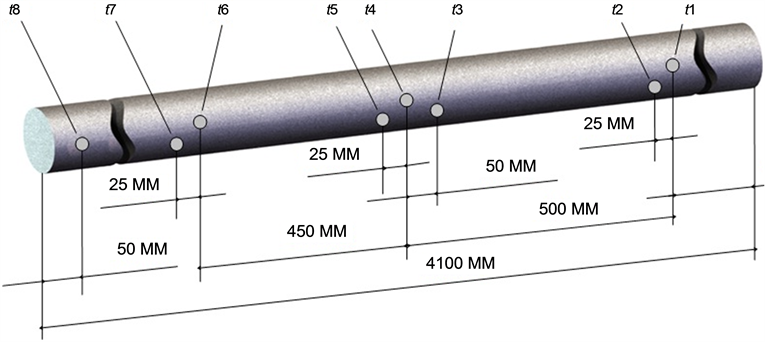
Figure 7. Scheme of thermocouples’ installation along the billet’s length in diameter of 100 mm.
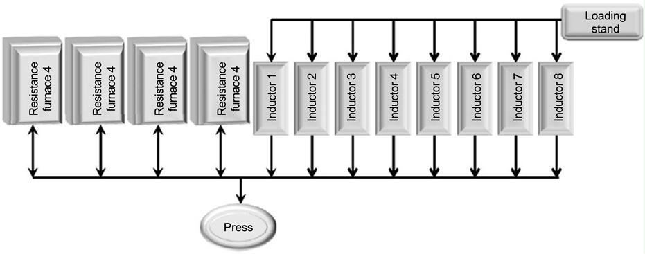
Figure 8. Schematic diagram of the line for heating billets in the induction and resistance furnaces before pressing.
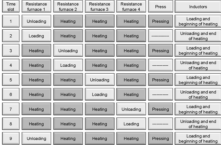
Figure 9. Mission profile of the line for heating billets in the induction and resistance furnaces before pressing.
of the temperature field and strong execution of the temperature profile during the heating time are essential for thermal processing of non-ferrous alloys before plastic deformation.
With all the known benefits of the induction heating technology it is necessary to note the impossibility of achieving absolute uniformity of temperature fields in the billets due to the difference in temperature between the environment in the inductor and the final temperature of the billet.
Specific examples of optimal heating of zirconium billet in the two-layer stage induction heater and continuous heating of long-length titanium billet in several inductors are presented in the paper.
The decision of the given problems would be impossible without numerical simulation, because mathematical simulation is necessary part of equipment’s designing and development of technology. Oscillating induction furnace is used for precise heating of long titanium billets. For special alloys it is necessary to use resistance furnaces for homogenization of billets’ temperature after heating in the inductors.
Using of the software packages UNIVERSAL and COIL [3] allows designing induction systems for precise high-temperature heating of alloys of various metals with high accuracy and low cost of time. With the help of these programs the user can receive all required characteristics of induction system, including distribution of the temperature and electromagnetic fields in loading, power, electrical efficiency, power factor, current of inductors etc.
References
- Nemkov, V.S. and Demidovich, V.B. (1988) Theory and Computation of Induction Heating Devices. Leningrad, Energoatomizdat, 280p. [In Russian].
- Demidovich, V.B. and Maslikov, P.A. (2013) Role of MHD Effects for the Development of Liquid Phase in the Titanium Ingot by Induction Melting. Induction heating, 33-36.
- Demidovich, V. (2012) Computer Simulation and Optimal Designing of Energy-Saving Technologies of the Induction Heating of Metals. Thermal Engineering, 59, 1023-1034. http://dx.doi.org/10.1134/S0040601512140030
- Demidovitch, V., Nikitin, B. and Olenin, V. (2007) Induction Installations for Heating Long Cylindrical Billets before Metal Forming. Russian Metallurgy (Metally), 98-102.
- Demidovich, V., Olenin, V. and Tchmilenko, F. (2008) Method of Induction Heating of the Long Billets. Patent RF № 2333618.