Journal of Electromagnetic Analysis and Applications
Vol.5 No.8(2013), Article ID:35491,3 pages DOI:10.4236/jemaa.2013.58052
Weakly Guiding Fibers and LP Modes in Circular and Elliptical Waveguides
![]()
Faculty of Engineering Multimedia, University Cyberjaya, Cyberjaya, Malaysia.
Email: shamini.pillay@mmu.edu.my
Copyright © 2013 Shamini Pillay et al. This is an open access article distributed under the Creative Commons Attribution License, which permits unrestricted use, distribution, and reproduction in any medium, provided the original work is properly cited.
Received April 26th, 2013; revised June 3rd, 2013; accepted July 12th, 2013
Keywords: Linearly Polarized Modes; Weakly Guiding Fibers; Circular Waveguides; Elliptical Waveguides
ABSTRACT
This paper gives the simple and logical approach of LP modes in circular and elliptical waveguides. Earlier the basic approach of modes in circular and elliptical fibers was studied by the authors. In this paper, the role of radial antinode in circular and elliptical waveguides is given clearly. Splitting of modes in circular and elliptical fiber has been discussed.
1. Introduction
Optical fibers (or waveguides) are important components of optical communication systems and information technology [1-7]. The aim of this paper is to describe LP modes in circular and elliptical waveguides. These LP modes consist of certain patterns of electromagnetic waves formed within the fiber due to structurally imposed (transverse) boundaries on the propagation fields. Each mode is a pattern of electric and magnetic field distributions that is repeated along the fiber at equal intervals. In modern communication systems we use as few modes as possible so that the interaction among several modes is minimized. Because optical fibers are used as basic mediums for transmission of optical signals, it is useful to make a detailed study of mode designation in optical waveguides.
2. Circular Waveguides
In weakly guiding fibers where In weakly guiding fibers where  is much less than 1 (n1, n2 being the core and the cladding refractive index) it is found convenient to describe the modes in terms of linearly polarised modes or LP modes.
These LP modes are due to the superposition of HE or EH modes. However, the LP modes are not exact modes of the step-index fiber and each LP-mode has many degenerate modes.
Apart from degeneracy, there is also an instability of the lobe orientations of the fields.
In weakly guiding fibers one can construct modes whose transverse fields are polarised in one direction. In elliptical fibers the fiber can suport two types of mode, one polarised predominantly in the x-direction and the other polarised predominantly in the y-direction.
In actual practice, in fibers for telecommunication purposes the relative core-cladding index difference  is usually kept less than 0.02.
This practical requirement permits us to simplify the mathematical analysis by considering what is known as the scalar wave equation in terms of a field variable y which may represent any of the cartesian components of the E and H fields. The boundary conditions also become simpler so that y and its radial derivative may be treated as continuous across the core-cladding boundary. The modes now are designated as  modes [8] the letters L and P standing for the phrase “Linearly polarised” The suffix
  stands for the
  th order Bessel function which corresponds to the cutoff condition for the mode and the other suffix m enumerates the successive zeroes of the corresponding Bessel function. If we show the positions of the field antinodes of a particular mode on the cross-section of the fiber, the mode
  will have
  antinodes in a ring of a certain radius and there will be n such rings on the cross-section thus in Figure 1 we show the antinodes of LP31 and in Figure 2 we show the antinodes of LP52. In a similar manner we can show the antinodes of LP42 and LP62 in Figure 3 and Figure 4 respectively.
The lowest order mode (fundamental mode) which is never cutoff is represented by LP01 and this corresponds to the HE11 mode of the previous section. The corre-
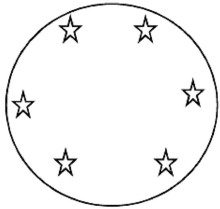
Figure 1. Antinodes for linearly polarized modes LP31.
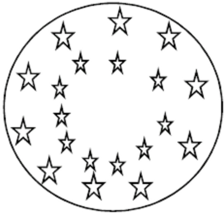
Figure 2. Antinodes for linearly polarized modes LP52.
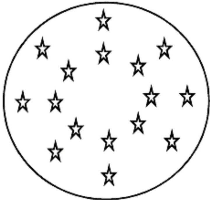
Figure 3. Antinodes for linearly polarized modes LP42.
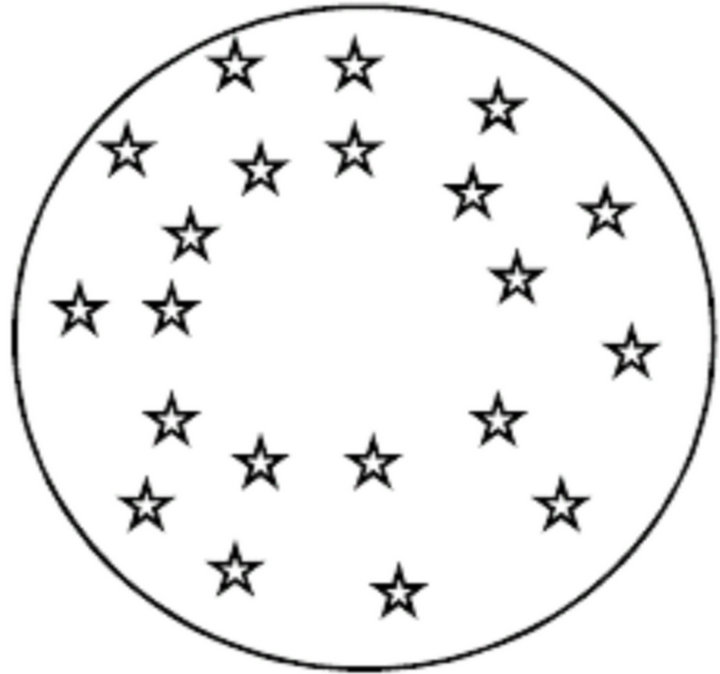
Figure 4. Antinodes for linearly polarized modes LP62.
spondence between the mode description such as HEmn etc. and the LP-modes are as follows:

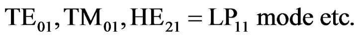
As a precaution we must note that for LP0m modes there will be no radial antinode at the center of the cross section.
3. Elliptical Waveguides
So far we have considered only fibers of circular crosssection. Now we turn to elliptical cross-sections. Since the ellipse is less symmetrical than the circle there can be two orientations for the field configuration in elliptical fibers. The fields in an elliptical fiber can be described in terms of Mathieu functions which are rather complicated functions. Mathieu functions are generally grouped in to two classes:
1) The even Mathieu functions; and 2) The odd Mathieu function.
A hybrid mode in an elliptical fiber is designated by a prescript, e or o, where e and o stand for the even mode and the odd mode respectively. The axial magnetic field of an even mode is represented by even Mathieu functions whereas the axial electric field of an even mode is represented by an odd Mathieu functions. This mode is symbolically represented as the eHEmn mode. In the case of the odd hybrid mode oHEmn the axial magnetic field is represented by an odd Mathieu function and the axial electric field is represented by an even Mathieu function.
In a similar manner, one can describe the EH modes. The axial electric field of an even mode is represented by even Mathieu functions whereas the axial magnetic field of an even mode is represented by an odd Mathieu functions. This mode is symbolically represented as the eEHmn mode. In the case of the odd hybrid mode oEHmn the axial electric field is represented by an odd Mathieu function and the axial magnetic field is represented by an even Mathieu function. Now we turn to LPlm modes in the case of elliptical waveguides. Mode which is designated by a prescript, e or o, where e and o stand for the even mode and the odd mode respectively. So in this case the mode will be symbolically represented by eLPlm mode and oLPlm mode. In eLPlm mode and oLPlm mode the letters L and P standing for the phrase Linearly polarised the suffix l stands for the lth order Mathieu function which corresponds to the cut off condition for the even mode and odd mode and the other suffix m indicates the successive zeros of the corresponding Mathieu functions.
For linearly polarized modes in elliptical fibers the hybrid LP11 mode is split in to even LP11 and odd LP11 modes with well-defined mode intensity patterns. The even LP11 and odd LP11 modes have significantly different cutoff wavelengths, which allow the existence of a wavelength range within which only even LP01 and LP11 modes are supported by the fiber. The elliptical core fibers that support two stable special modes, the LP01 and LP11 even/odd modes, are called elliptical core two-mode fibers. One important application of these fibers is to interferometric model/polarimetric sensors, which is useful to measure strain and temperature. The antinodes of even LP11 and odd LP11 are shown in Figure 5 and Figure 6 respectively.
4. Splitting of Modes in Circular and Elliptical Fibers
All guided optical modes in a circular symmetric optical fiber are fundamentally a transverse electric (TEom), transverse magnetic (TMom) or a hybrid mode (EHnm or HEnm). This is described in the weekly guiding approximation, where the solution is the well known LPnm modes. The LPnm modes are due to superpositions of the transverse and hybrid modes.
Modes splitting of higher order is due to the fact that the degeneracy of the linearly polarized modes in circular case is lifted as the fiber core is made elliptical. Thus the TEom and TMom modes become the hybrid modes oEH0m and eHE0m when it’s made elliptical. The prefix e and o indicates even or odd function. Each hybrid mode from the from the circular symmetric case splits in the elliptical case into two hybrid modes, as symmetry dictates only two field configuration in an elliptical core fiber. This can be seen by EHnm that splits into eEHnm and oEHnm. In weekly guiding approximation, there is no observable splitting in cutoff measurements between the even and odd versions of a given hybrid mode, as b/a is changed from 1 to 0.1. As a consequence only the LP1m and LPnm (n > 2) split as fibre becomes elliptical and each of these LP modes will only split into two other modes called eLP and oLP, where e and o here denotes if the LP mode is even or odd. A summary is further given in Table 1.
5. Conclusion
This paper gives the basic and logical concept of LP
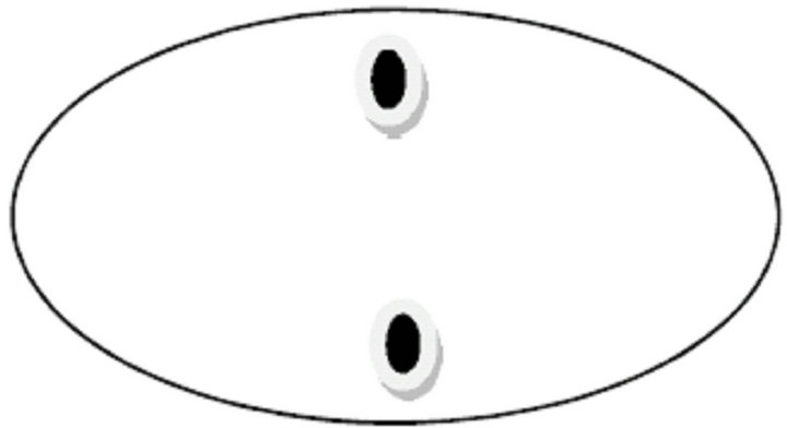
Figure 5. Antinodes for even linearly polarized modes.

Figure 6. Antinodes for odd linearly polarized modes LP11.
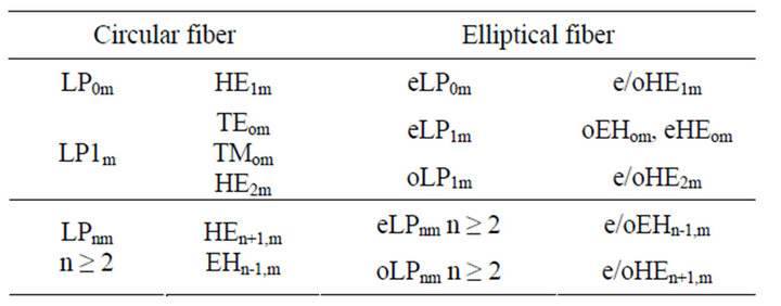
Table 1. Mode splitting in weakly guiding approximation.
modes in circular waveguides and even and odd LP modes in elliptical waveguide. Some basic figures are introduced when necessary without derivation. The application of modes is useful in illumination engineering. This helps our attention on the physical description of the problem.
REFERENCES
- C. Yeh, “Guided-Wave Modes in Cylindrical Optical Fibers,” IEEE Transactions on Education, Vol. E-30, No. 1, 1987, pp. 43-51. doi:10.1109/TE.1987.5570585
- D. Gloge, “Weakly Guided Fibers,” Applied Optics, Vol. 10, No. 10, 1971, pp. 2252-2258. doi:10.1364/AO.10.002252
- D. Kumar and O. N. SinghII, “Modal Characteristic Equation and Dispersion Curves for an Elliptical Step-Index Fiber with a Conducting Helical Winding on the CoreCladding Boundary: An Analytical Study,” IEEE Journal of Light Wave Technology, Vol. 20, No. 8, 2002, pp. 1416-1424. doi:10.1109/JLT.2002.800799
- E. Snitzer, “Cylindrical Dielectric Waveguide Modes,” Journal of Optical Society of America A, Vol. 51, No. 5, 1961, pp. 491-498. doi:10.1364/JOSA.51.000491
- M. Hashimoto, “Hybrid Modes of Graded-Index Optical Fibres,” Electronics Letters, Vol. 17, No. 18, 1981, pp. 659-661.
- A. Safaai-Jazi and G. L. Yip, “Classification of Hybrid Modes in Cylindrical Dielectric Optical Waveguides,” Radio Science, Vol. 12, No. 4, 1977, pp. 603-609.
- K. Morishita, “An Exact Analysis of Group Velocity for Propagation Modes in Optical Fibers,” IEEE Transactions on Microwave Theory and Techniques, Vol. 30, No. 11, 1982, pp. 1821-1826. doi:10.1109/TMTT.1982.1131330
- D. Kumar and P. K. Choudhury, “Introduction to Modes and Their Designation in Circular and Elliptical Fibers,” American Journal of Physics, Vol. 75, No. 6, 2007, p. 546.