Journal of Electromagnetic Analysis and Applications
Vol.5 No.2(2013), Article ID:28501,7 pages DOI:10.4236/jemaa.2013.52011
Impact of EAS Systems on Implanted Cardiac Pacemakers and Defibrillators
![]()
Institute of Health Care Engineering with European Notified Body of Medical Devices, Graz University of Technology, Graz, Austria.
Email: norbert.leitgeb@tugraz.at
Received November 24th, 2012; revised December 26th, 2012; accepted January 10th, 2013
Keywords: RFID; Interference; Electromagnetic Fields; Electromagnetic Compatibility; Safety
ABSTRACT
To investigate electromagnetic interference (EMI) of electromagnetic fields (EMF) from electronic article surveillance (EAS) systems with electronic implants numerical anatomical models of pacemaker patients were generated accounting for different implantation sites (left pectoral, right pectoral and abdominal) and body size. Induced interference voltages were calculated with a software package applying the Finite Integration Technique and analysed in dependence on frequency. Results were referred to reported maximum magnetic fields levels measured at EAS systems in the ELF, IF and RF range. With reference to electromagnetic immunity requirements of safety standards of implanted cardiac pacemakers and defibrillators, the numerical analysis showed that the relevance of interference depends on the applied EMF frequency. At EAS systems operating in the RF range, EMI and consequential inadequate pacing is rare but cannot be ruled out. The probability of such events increases at EAS systems in the IF range and even more in the ELF range. Since interference is encountered already at yet existing systems, the situation would be worse if future systems would further increase their emissions by making use of the elevated reference levels recommended in updated exposure guidelines.
1. Introduction
Worldwide Electronic Article Surveillance systems (EAS) and personal identification systems (PIS) are widely used for a variety of purposes such as protecting against theft, for object identification and access control, and passing through gates has become frequent in daily life. EAS systems may apply electromagnetic fields (EMF) at allocated frequencies in the extremely low frequency (ELF) range (using 20 - 18,000 Hz) to identify magnetic tags, in the intermediate frequency (IF) range at 58 - 60 kHz acoustomagnetic resonance and swept radiofrequency systems (1.8 - 10 MHz), as well as in the radio frequency (RF) range with microwave systems operating at 900 and 2450 MHz, respectively.
There are already several reports on measured magnetic fields of EAS systems [1-8]. They indicate large differences in amplitudes including considerable excess of reference levels as recommended by the International Commission on Non-Ionising Radiation Protection (ICNIRP) and the European Council [9-11].
In view of the omnipresence of EAS devices in daily life and the increasing number of patients with active implants there is concern about adverse electromagnetic interference with implanted cardiac pacemakers (CPM) and cardioverter defibrillators (ICD). In general, implanted CPM are able to adjust their stimulation rate to physiologic needs, and ICD identify tachycardia and/or fibrillation based on measuring patient’s (remaining) intrinsic electric cardiac activity via a sensing electrode which is contacted to the cardiac muscle of either the atrium and/or ventricle. It picks up the cardiac electric signal in terms of electric potential difference between electrode tip and pacemaker can. This allows controlling delivered pacing pulses by sensed cardiac biosignals. However, sensing cardiac activity makes CPM and ICD vulnerable to electromagnetic interference. The reason is that according to the well-known Maxwell’s equations alternating magnetic fields induce inside the body an intracorporal electric field (and hence eddy current densities) with consequential potential differences. The potential differences (=voltages) may be picked up by the pacemaker electrode tip (relative to the can potential) and add to the cardiac signal as an interference voltage. If such induced interference voltages are high enough they may cause adverse effects in terms of permanent functional changes. If they are such as to be confused with electrocardial signals, they may temporarily adversely alter functioning of CPM and ICD in terms of inadequate pacing, and hence pose health risks to patients.
There are already experimental investigations and in vivo experiments at patients with implanted CPM and ICD reporting interference of EAS devices with electronic implants with increased vulnerability of CPM compared to ICD. The reported percentage of affected implants was up to 67% CPM and 47% ICD, respectively. Encountered interactions included asynchronous pacing, tachycardia, inhibition, and paced beats, in some patients causing symptoms such as palpitation or presyncope [12- 16]. Measurements of EAS-related magnetic field exposure justify concern about adverse electromagnetic interference with implanted cardiac pacemakers (CPM) or cardioverter defibrillators (ICD), in particular since the prevalence of pacemaker patients among the general population is increasing and amounts already to about 0.8% of the general population. However, there is a wide variety of types of implantable CPM and ICD and their sensing thresholds of cardiac signals may be differently adjusted. Therefore, reported experimental findings at particular persons with particular implants and particular settings demonstrate the risk of interference but do not allow drawing any quantitative conclusions yet.
In the meanwhile, recommended reference levels of environmental EMF have been considerably increased in the ELF and IF range [10] which would allow further increasing EAS field levels and consequently may increase CPM and ICD interference probability.
To provide quantitative information, by numerical simulation at self-generated numerical-anatomical models of pacemaker patients (accounting for all typical implantation sites) this paper analyses the interference of monopolar CPM and ICD with magnetic emissions from EAS by using commercial simulation software packages. To allow conclusions independent from selected particular cases results are assessed with regard to electromagnetic immunity requirements as defined in medical device safety standards.
2. Method
To investigate interference (EMI) of electromagnetic fields from EAS systems several numerical models of pacemaker patients were generated accounting for different implantation sites and body size. An average human was represented by the well-established numerical male model NORMAN with a body mass index (BMI) of 23.6. It has been derived from series of magnetic resonance images (MRI) of an average European man (73 kg, 176 cm) with a spatial resolution of 2 × 2 × 2 mm voxels [17]. Its biologic tissues were segmented into 35 different types. Dielectric values of body tissues were taken from the literature [18]. To check for the influence of interpersonal variability the anatomical model Visible Man (103 kg, 186 cm) representing a Caucasian obese man with BMI 29.8 has also been investigated (Visible Human Projekt® National Library of Medicine, Maryland). It is separated into 31 different biologic tissues.
Numerical models of pacemaker patients were generated by numerically implanting the digital model of a cardiac pacemaker into the anatomical models with the pacemaker can below the cutis at the conventional implantation sites (left pectoral, right pectoral and abdominal). The uniopolar electrode was electrically insulated and inserted via the vena cava and vena subclavia, respectively, followed the veins and finally contacted the right ventricular apex [19-21]. In abdominal position the can was also implanted below the skin, the electrode was inserted into the vena femoralis and followed the veins until contact with the right ventricular apex (Figure 1). Since CPM and ICD devices differ mainly in the operating software and delivered electric pulses the numerical CPM model can also be used for assessing ICD interference voltages.
The intracorporal distributions of induced electric fields were calculated with the commercial software packages CST Studio® Suite 2009, depending on the investigated frequency with the Low Frequency Solver and High Frequency Solver, respectively [22] applying the Finite Integration Technique [23]. Induced CPM interference voltages were determined by integrating the electric field strength along the way between cardiac electrode tip and pacemaker can.
To allow identification of exposure variation with frequency and device type a survey of magnetic field (MF) levels generated by EAS systems has been elaborated by a literature review [1-8]. To be independent from specific EAS devices and their individual field pattern exposures to homogeneous magnetic fields have been analysed for
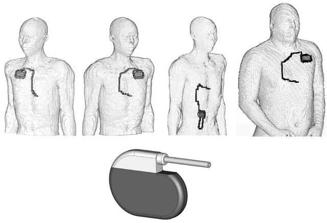
Figure 1. Numerical models of pacemaker patients representing an average European man with right pectoral, left pectoral, abdominal implantation, based on the modified model NORMAN as well as the obese model with left pectoral implantation (from left to right) and the model of the cardiac pacemaker (below).
worst case body orientation over the entire frequency range from ELF to RF. This should allow identifying frequency-specific effects, in particular the onset and impact of the RF electromagnetic skin-effect which affects the intracorporal distribution of induced electric fields. To allow concluding on EAS exposures, in a second step these results were scaled by maximum reported EAS field values. Calculated interference voltages were compared with electromagnetic immunity levels as defined in related device safety standards.
3. Results
For exposure to homogeneous fields in worst case orientation results showed only minor differences (8%) between left and right pectorial implantation while 2.5 fold lower values were encountered in case of abdominal implantation. The results of the normal and obese model indicated the magnitude of interpersonal variance with regard to induced CMP interference voltages.
At the obese model the interference voltage was 20% - 57% higher compared to the slim case. This is mainly due to different induction loop areas.
The reported spatial peak values of magnetic field strengths, measured at walk-through gates are summarized in Figure 2 together with former ICNIRP’s reference values [9] and the actual recommendation according to the revision within the ELF and IF range up to 10 MHz [10] which resulted in an elevation of reference values up to 256 fold in the ELF range and up to 287 fold in the IF range, and left a discontinuity at 10 MHz, the borderline of the two recommendations.
The profile across the gate of EAS devices is symmetric with the maximum values at the surface of gates and a minimum in the centre. Among EAS devices the maximum MF amplitudes vary considerably both at particular frequencies and over the entire frequency range. MF
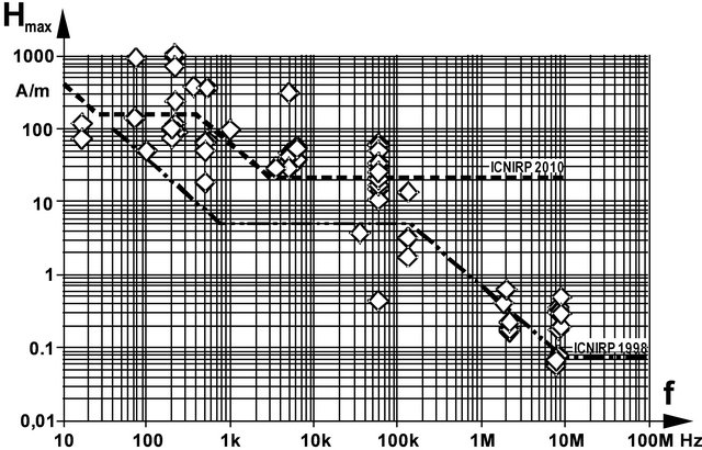
Figure 2. Summary of spatial peak values of measured maximum magnetic field strengths at EAS gates, and reference values recommended by ICNIRP 2010 and 1998, respectively.
strengths of different types of EAS exhibit a span of up to 144 fold. Reference values may be exceeded up to 13 fold compared to ICNIRP’s revised recommendation [10] and even up to 60 fold with regard to former values, respectively. Seventy-five percent of existing EAS devices exceed ICNIRP’s initial reference values [9] which are still in force in several national regulations worldwide. Even 43% EAS devices still exceed the (new) MF reference values. However, it must be stressed, that this does not necessarily mean violation of basic restrictions although this may happen for worst case exposure scenarios [1]. Since EAS generated MF are inhomogeneous, coupling within gates is less efficient than at homogeneous fields to which reference values are related to.
The analysis of exposures to homogeneous MF with constant amplitude (arbitrarily chosen as 1 mT) demonstrates that CPM interference voltage initially increases linearly with frequency, as follows from induction law. However, in the RF range the dependency deviates from linearity. This can be explained by the fact that induced eddy currents themselves generate magnetic fields acting against and, hence, weakening the initial field. In the RF range this effect can become high enough to partly compensate the initial field at central body regions which consequently shifts induced electric currents towards superficial tissue regions. This well-known mechanism (magnetic skin-effect) results in decreasing CPM interference. The onset of reduced interference due to the skin effect started at about 1 MHz and progressively increases with frequency (Figure 3).
The skin effect with shifting current densities towards superficial areas and reduction in the body centre is demonstrated by the induced intracorporal electric current densities distributions as shown in Figure 4 for 50 Hz and 500 MHz, respectively. In a worst case approach, CPM and ICD interference voltages induced by EAS gate fields can be estimated by scaling the results of homogeneous field exposure by measured EAS magnetic field strengths.
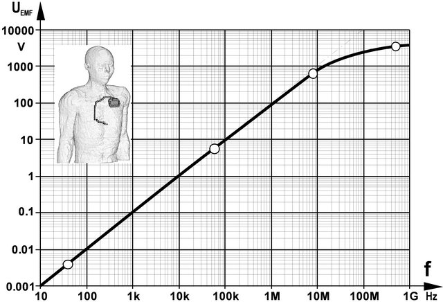
Figure 3. CPM interference voltage UEMF induced by 1 mT MF in a patient with left pectoral CPM implantation.
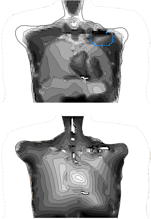
Figure 4. Current densities within a frontal plane across the CPM electrode tip induced by homogeneous magnetic fields of 50 Hz (above) and 500 MHz (below).
The overview of resulting interference voltages is presented in Figure 4 together with frequency-dependent immunity levels (straight line) as defined in safety standards of active medical implants [24-26]. It can be seen that even under this worst case approach interference voltages induced by emissions of RF EMF EAS systems remain well below immunity levels. However, voltages may exceed immunity levels by up to 28 fold in the ELF and IF range. The comparison between the slim and obese CPM patient revealed that induced interference voltages may differ by 57%.
4. Discussion
Cardiac sensing makes CPM and ICD vulnerable to EMFinduced interference signals which might be confused with cardiac activity and subsequently cause inadequate pacing.
Medical device safety standards define interference as “any harm caused by a device’s susceptibility to electric and/or electromagnetic influences, in particular any device malfunction persisting after exposure,” [24-26]. Therefore, related to a specified sensing threshold standards define EMI immunity levels of interference voltages to prevent from induced persisting malfunction. To allow general conclusions calculated interference voltages are compared with these requirements. This allows concluding on potential adverse EMI effects at patients with implanted CPM or ICD exposed to MF from EAS gates.
Published literature reports on decreasing EAS interference with time from up to 96% CPM [16] to only 6% twelve years later (Seidman et al. 2010). This can be explained by the fact that with time electromagnetic compatibility requirements have become stricter although the washout period of already implanted CPMs may be relevant. Apart from adverse events such as breakage of electrodes the lifetime of CPMs is mainly determined by battery exhaustion. By now 57% of the CPM stand 8 - 12 years and 10% even longer than 12 years [27]. The duration within the distribution chain may prolong the washout period by additional years.
In daily life implantable CPM and ICD may exhibit different settings of their electrocardial sensing threshold. Vulnerability to EMI increases if the threshold is lowered. This is possible by about the 7 fold such as in case atrial lead position is suboptimal or cardiac signals are unusual low [24]. However, it is acknowledged that such a decreased sensing threshold is a tradeoff with increased risk of adversely sensing myopotentials.
The difference between left and right pectoral site is about 8% but induction voltages are 2.5 fold lower at abdominal implantation. At the obese model the loop area and consequently the induced interference voltage was 14% larger. Based on X-ray investigations the upper limit of induction area can be supposed to be 400 cm² [24]. This would increase the induced voltages by 2.7 fold. However, some uncertainties about loop areas remain since due to its volumetric nature the pathway of the electric currents from electrode tip to CPM cannot be easily defined. In addition, it is common surgical practice to wind the electrode surplus length around the CPM can and thus generating additional loop areas and consequently increasing the overall interference area.
Orientation of the body within the EAS gate may reduce the effective induction loop area, e.g. at the NORMAN CPM model with left pectorial implantation from worst case 150 cm² (frontal orientation of the MF) to best case 52 cm² (lateral orientation of the MF) by the 2.9 fold. It could be argued that these induction loop areas refer to unipolar CPM while in most cases sensing is performed in bipolar mode which dramatically reduces EMI. In fact, 96.8% CPM start with bipolar operation at implantation time [27]. However, since tissue reaction might degrade pacing efficiency it may be necessary to change to the unipolar operation mode later on which consequently increases the percentage of CPM operating in unipolar mode.
Consequently, encountering CMP operating in unipolar mode cannot be ruled out. The increased use of bipolar devices would just reduce the probability of interference rather than preventing from interference as such. Therefore, from the patient protection’s point of view, worst case scenarios including unipolar operation remain valid.
Induced interference voltages based on maximum EAS MF emission still show a distance to required immunity levels up to 6.2 fold (1.8 MHz) and 10.3 fold (8.2 MHz), respectively (Figure 5). Accounting for the 2.7 fold increase of the interference voltage due to anatomical variance the immunity requirements would be still met, however, the remaining safety margin would allow reducing sensing thresholds only by 2.3 fold (while the reduction requirement may be 7 fold). Therefore, it can be concluded that adverse interference with CPM and ICD at existing radio frequency EAS should be rare but cannot be ruled out.
In the ELF range the maximum induced interference voltages exceed the immunity level by 28.2 fold and 3.2 - 13.5 fold in the IF range. With regard to the usual passby scenario it has to be acknowledged that the magnetic field in the centre of the EAS gate is lower than the reported maximum values. Based on reported measurements this reduction can be estimated to be about 13.9 fold [28]. In addition, passing gates is associated with a favourable orientation of the body relative to the MF vector. This makes the effective induction loop area smaller by about 2.9 fold compared to the worst case orientation when leaning with the back on the gate and the MF orientation perpendicularly oriented. Accounting for anatomical variance (2.7 fold) results in an overall reduction factor 14.9 (13.9 × 2.9/2.7).
This is larger than the 3.2 - 13.5 fold excess of the immunity level in the IF range. Consequently, pass-by exposures in the centre of existing EAS gates operating in the IF range should not cause interference problems with
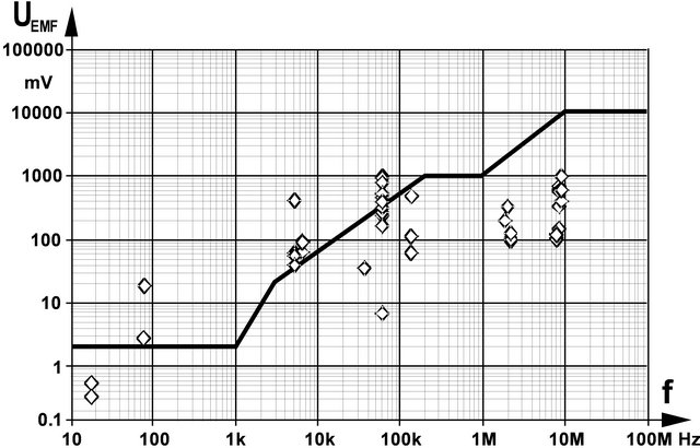
Figure 5. Interference voltage UEMF induced by EAS gate magnetic fields together with CPM immunity levels (derived from EN 45502-2 in dependence on frequency.
CPM and ICD with normal sensing threshold settings. However, adverse interference may occur under unfavourable conditions (body’s worst case orientation and low sensing threshold setting).
In the ELF range EMI cannot be excluded in case of unfavourable body orientation even in a pass-by situation. In addition, interference probability is considerably increased when leaning towards the gate and/or if the sensing is set to lower thresholds.
Not every interference might be relevant. Induced interference voltages may either be ignored if they are below the expected electrocardial signal amplitude, they may be confused with the biosignal and consequentially cause inadequate pacing, or they may be high enough to be identified as artificial and consequentially cause changing to the asynchronous safety mode.
If interference signals mimic patient’s cardiac activity this may have the following consequences:
1) In case of demand pacemakers pacing may be suppressed. This could be ignored if cardiac activity exists, anyway. Only if it coincides with a period of persisting lack of patient’s own cardiac activity suppressed pacing might lead to adverse effects if the required conditions remain fulfilled sufficiently long.
2) In case of triggered pacemakers interference signals may increase pacing rate up to the device-inherent safety limit (runaway protection) of about 180 beats/min. Cardioverter defibrillators could be misled to treat suspected tachycardia by pacing according to their anti-tachycardia program.
In a pass-by situation potential functional changes are transient and hence, may be tolerable. However, waiting next to the gates, in particular leaning at them should be avoided.
5. Conclusion
The numerical analysis of the electromagnetic compatibility of EAS systems with implanted CPM and ICD showed that inadequate pacing caused by existing EAS systems cannot be ruled out. At systems operating in the RF range, interference is rare but existent at RF systems. The probability is increased at EAS systems applying EMF in the IF range and even more in the ELF range. Since interference is encountered already at yet existing systems, the situation would be worse if future systems would further increase their emissions by making use of the elevated reference levels recommended in updated exposure guidelines.
REFERENCES
- W. Joseph, G. Vermeeren, L. Verloock and F. Goeminne, “In Situ Magnetic Field Exposure and ICNIRP-Based Safety Distances for Electronic Article Surveillance Systems,” Radiation Protection Dosimetry, Vol. 148, No. 4, 2012, pp. 420-427. doi:10.1093/rpd/ncr206
- G. Schmid, R. Überbacher, S. Cecil, A. Escorihuela-Navarro, D. Sainitzer and A. Weinfurter, “Determination of the Exposure to Electromagnetic Fields Generated by Radio Frequency Indentification (RFIF) Technologies,” 2012. http://doris.bfs.de/jspui/handle/urn:nbn:de:0221-201208089216
- M. Martinéz-Búrdalo, A. Sanchis, A. Matín and R. Villar, “Comparison of SAR and Induced Current Densities in Adults and Children Exposed to Electromagnetic Fields from Electronic Article Surveillance Devices,” Physics in Medicine and Biology, Vol. 55, No. 4, 2010, pp. 1041- 1055. doi:10.1088/0031-9155/55/4/009
- J. Trulsson, G. Anger and U. Estenberg, “Assessment of Magnetic Fields Surrounding Electronic Article Surveillance Systems in Sweden,” Bioelectromagnetics, Vol. 28, 2007, pp. 664-666. doi:10.1002/bem.20359
- W. Boivin, J. Coletta and L. Kerr, “Characterization of the Magnetic Fields around Walk-Through and Hand-Held Metal Detectors,” Health Physics, Vol. 84, No. 5, 2003, pp. 582-593. doi:10.1097/00004032-200305000-00003
- J. H. Bernhardt, A. F. McKinlay and R. Matthes, Eds., “Possible Health Risk to the General Public from the Use of Security and Similar Devices,” ICNIRP 12/2002, Munic, 2002.
- C. Harris, W. Boivin, S. Boyd, J. Coletta, L. Kerr, K. Kempa and S. Aronoiw, “Electromagnetic Field Strength Levels Surrounding Electronic Article Surveillance (EAS) Systems,” Health Physics, Vol. 78, No. 1, 2000, pp. 21- 27. doi:10.1097/00004032-200001000-00005
- G. Neubauer, H. Molla-Djaffari, K. D. Pühringer, H. Garn, N. Winkler, H. Preib and G. Schmid, “Measurement and Safety Assessment of Electromagentic Fields around AntiTheft Devices (German),” AUVA Report #23, Vienna, 1998.
- ICNIRP, “Guidelines for Limiting Exposure to Time-Varying Electric, Magnetic and Electromagnetic Fields (1 Hz to 100 kHz),” Health Physics, Vol. 99, No. 6, 2010, pp. 818-836.
- ICNIRP, “Guidelines for Limiting Exposure to Time-Varying Electric and Magnetic Fields (1 Hz to 100 kHz),” Health Physics, Vol. 99, No. 6, 2012, pp. 818-836.
- European Council, “Recommendation Limiting the Public Exposure to Electromagnetic Fields (0 Hz to 300 GHz),” Official Journal European Communities No L199/59, 1999.
- S. J. Seidman, R. Brockman, B. M. Lewis, J. Guag, M. J. Shein, W. J. Clement, J. Kippola, D. Digby, C. Barber and D. Huntwork, “In Vitro Tests Reveal Sample Radiofrequency Identification Readers Inducing Clinically Significant Electromagnetic Interference to Implantable Pacemakers and Implantable Cardioverter Defibrillators,” Heart Rhythm, Vol. 7, No. 1, 2010, pp. 99-107. doi:10.1016/j.hrthm.2009.09.071
- W. Irnich, “Electronic Security Systems and Active Implantable Medical Devices,” Pacing and Clinical Electrophysiology, Vol. 25, No. 8, 2002, pp. 1235-1258. doi:10.1046/j.1460-9592.2002.01235.x
- R. Frank, “Behaviour of 20 Pacemakers as Patients Pass through 2 Models of Theft-Detection Doors,” Annals of Cardiology and Angiology, Vol. 49, No. 3, 2000, pp. 187- 197.
- J. Mugica, L. Henry and H. Podeur, “Study of Interactions between Permanent Pacemakers and Electronic Antitheft Surveillance Systems,” Pacing and Clinical Electrophysiology, Vol. 23, No. 3, 2000, pp. 333-337. doi:10.1111/j.1540-8159.2000.tb06758.x
- M. E. McIvor, J. Reddinger, E. Floden and R. C. Sheppard, “Study of Pacemaker and Implantable Cardioverter Defibrillator Triggering by Electronic Article Surveillance Devices (SPICED TEAS),” Pacing and Clinical Electrophysiology, Vol. 21, No. 10, 1998, pp. 1847-1861. doi:10.1111/j.1540-8159.1998.tb00002.x
- P. J. Dimbylow, “FDTD Calculations of the Whole Body Averaged SAR in an Anatomically Realistic Voxel Model of the Human Body from 1 MHz to 1 GHz,” Physics in Medicine and Biology, Vol. 42, No. 3, 1997, pp. 479-490. doi:10.1088/0031-9155/42/3/003
- S. R. Gabriel, W. Lau and C. Gabriel, “The Dielectric Properties of Biologic Tissues: Measurement in the Frequency Range 10 Hz-20 GHz,” Physics in Medicine and Biology, Vol. 41, No. 11, 1996, pp. 2251-2269. doi:10.1088/0031-9155/41/11/002
- N. Leitgeb, F. Niedermayr and C. Fuchs, “Impact of a Radio Frequency Electronic Article Surveillance (EAS) System on Active Implants,” Journal of Electromagnetic Analysis and Applications, Vol. 4, No. 9, 2012, pp. 353- 357. doi:10.4236/jemaa.2012.49049
- N. Leitgeb, F. Niedermayr, R. Neubauer and G. Loos, “Risk of Pacemaker Patients by TASER X26 Contact Mode Application,” Journal of Electromagnetic Analysis and Applications, Vol. 4, No. 2, 2012, pp. 96-100. doi:10.4236/jemaa.2012.42012
- N. Leitgeb, F. Niedermayr, R. Neubauer and G. Loos, “Interference of Implanted Cardiac Pacemakers With TASER X26 Dart Mode Application,” Biomedical Engineering, Vol. 57, No. 3, 2012, pp. 201-206.
- CST Studio® Suite, CST GmbH, Darmstadt, 2009. www.cst.com
- T. Weiland, “A Method for Discretically Solving Maxwell’s Equations for Six-Component Fields (in German),” International Journal of Electronics and Communication, Vol. 31, 1977, pp. 16-120.
- EN 45502-2-1:2003, “Active Implantable Medical Devices. Part 2-1: Particular Requirements for Active Implantable Medical Devices Intended to Treat Bradyarrhythmia (Cardiac Pacemakers),” 2003.
- EN 45502-2-2:2003, “Active Implantable Medical Devices. Part 2-1: Particular Requirements for Active Implantable Medical Devices Intended to Treat Tachyarrhythmia (Includes Implantable Defibrillators),” 2003.
- ANSI/AAMI PC69:2007: “Active Implantable Medical DevicesElectromagnetic CompatibilityEMC Test Protocols for Implantable Cardiac Pacemakers and Implantable Cardioverter Defibrillators,” 2007.
- A. Markewitz, “Annual Report on the German Cardiac Pacemaker Register,” 2009. http://www.pacemaker-register.de
- U. Estenberg, G. Anger and J. Trulsson, “Mapping of Magnetic Fields Surrounding EAS and RFID Systems,” SSI Rapport #3, Stockholm, 2006.