Journal of Electromagnetic Analysis and Applications
Vol.4 No.9(2012), Article ID:22476,4 pages DOI:10.4236/jemaa.2012.49051
Vehicular Radio Scanner Using Phased Array Antenna for Dedicated Short Range Communication Service
![]()
1Department of Electronics & Communication Engineering, Dr. B. C. Roy Engineering College, Durgapur, India; 2Microwave and Antenna Research Laboratory, Department of Electronics and Communication Engineering, National Institute of Technology Durgapur, Durgapur, India; 3Department of Electronics & Telecommunication Engineering, Bengal Engineering and Science University, Shibpur, India.
Email: tapas2k@gmail.com
Received July 10th, 2012; revised August 11th, 2012; accepted August 21st, 2012
Keywords: Intelligent Transportation System; Microstrip Phased Array Antenna; Tchebyscheff Polynomial; Electromagnetic Interference
ABSTRACT
Now a day’s accidents are very common due to increased population of vehicle. In order to ensure safety measures in the vehicle this paper has proposed some methodologies regarding careful driving by automatically scanning and analyzing the blind spot area of an intelligent mobile vehicle. A vehicular antenna with minimum perturbation is proposed to be fitted on the vehicle and collect information of the concern area which would ensure visibility of the operator i.e. masked or integrated within the car body. This paper has dealt with the design of Tchebyscheff polynomial based prototype planar microstrip phased array antenna and also redesigned the same when implemented in the body of the car being considered as an electromagnetically large element. Both the design has been experimentally verified with the measurement. The simulated and the measured results in both the cases are found to be in good agreement. More than 11 dB gain was observed at perfectly 30° angles from its broad side direction as desired for blind spot detection with minimum amount of electromagnetic interference inside the car.
1. Introduction
Intelligent Transport System (ITS) ensures mobility comfort and safety in transportation system. It also absorbs the hazards due to environmental impact. With the progress of the information processing technology, control systems to minimize accidents for the roadways have also been advanced hence one approach to improve the traffic safety is found and that is automatic collection of data by scanning the blind spot area of the vehicle [1] as shown in Figure 1. Many methods were proposed to detect the blind spot area but all of them had certain limitations. Devices like dynamic angling side view mirror [2], side view camera model [3], and shadow or edge features detector [4] were used for detecting blind spot area but their performance was affected during bad weather, fog or mist. Also we know that the mechanical systems, response time is more and the system is prone to wear and tear.
A radio frequency method has been proposed in this paper to scan the blind spot zone efficiently. Four rectangular microstrip antennas (RMSA) are arranged in linear configuration with optimal spacing between the patch elements to construct the phased array radar. A corporate feed network is used to feed the patch element unequally and a progressive phase shifter is designed with 108˚ delay elements to tilt the main beam in the desired direction and then the total unit is simulated and experimented after placing it on the car body which is electromagnetically a large element. The antenna works in the Dedicated Short-Range Communication Service (DSRCS) frequency band [5]. The design of the microstrip phased array antenna is discussed in Section 2 and after that to place the antenna; the design of the entire car is given in Section 3. Results and discussion are portrayed in Section 4 along with conclusion in Section 5.
2. Design of Microstrip Phased Array Antenna
The microstrip phased array antenna is designed for Dedicated Short Range Communication Service at 5.88 GHz with dielectric constant of 2.32 and substrate thickness of 0.785 mm. Firstly the dimension of the rectangular patch is computed as 16.322 mm by 19.8 mm using the method outlined in [6]. With computed inset feed length of 3.8 mm and for the above dimensions of the rectangular patch the return loss is found to be –8.09 dB
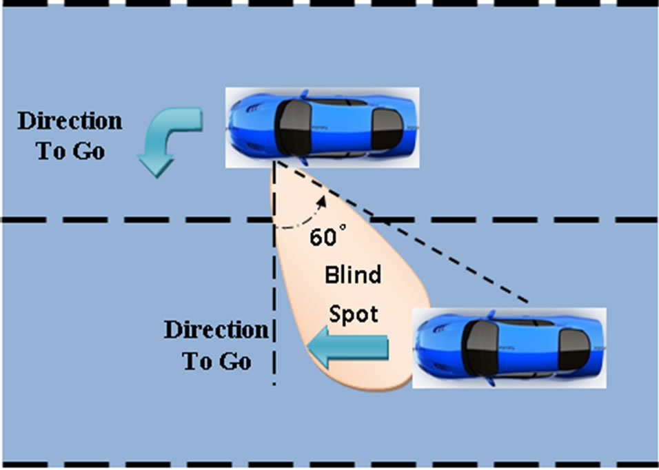
Figure 1. Surrounding regions of a vehicle.
with (30.1 + j26.7) ohm impedance at the feed position. The RMSA is simulated and optimized using Ansoft HFSSTM. After optimization the final length is found to be 16.4363 mm with inset feed length of 4.8225 mm keeping the width of the patch unchanged as shown in Figure 2.
By considering the above designed patch element, a four element linear array is realized and powered by Tchebyscheff current distribution. The spacing between the elements is kept considering the desired maximum scan angle in order to eliminate the grating lobes within the visible space of the phased array antenna. To optimize the performance of the antenna in respect of its side lobe level (SLL), mutual coupling and gain of the antenna array, the spacing between the elements is studied parametrically [7]. The results of the said study are tabulated in Table 1.
After optimization it is found that the optimum spacing between the elements is 0.6 l0 while considering, the main lobe to side lobe ratio below 20 dB, optimum mutual coupling and overall gain.
From Figure 1, it is observed that the beam of the antenna array is required to be tilted by an angle 30˚ away from the broad side direction. In view of the above a progressive phase shifter of –108˚ is designed with the help of 11.16 mm feed line length. The actual line length is considered as mt, where m = 0, 1, 2, 3.
To enhance the gain by maintaining the beam width and main lobe to side lobe ratio, the antenna elements are excited by Dolph Chebyshev current distribution. The array consist of four elements, thus third order Tchebyscheff polynomial is calculated. Hence the polynomial is solved and relative current ratio is computed as 1:1.7795:1.7795:1. Both equal and unequal power dividers are designed along with the progressive phase shifter.
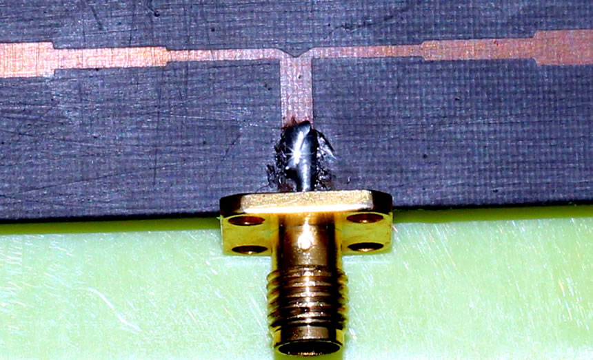
For equal power division, a 3 dB equal power divider is designed whose vertical arm is of 50 Ω line and two horizontal quarter-wavelength branch-lines are of 70.71
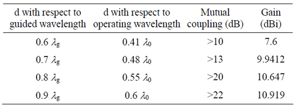
Table 1. Effect on mutual coupling and gain due to variation in spacing (d) between the elements.
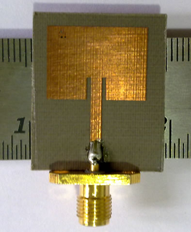
Figure 2. Photograph of the rectangular microstrip antenna element.
Ω is used [8]. It is shown in Figure 3(a).
To get the unequal current distribution, both the horizontal arm of the microstrip unequal power divider should be of different resistance and it is calculated as 46.368 Ω and 82.49 Ω. The structure is shown in Figure 3(b).
Generally for practical design purpose the gap between the corporate feed networks is taken small but the value of the gap less than 0.11 λ0 disturbs the frequency response of overall antenna array. The effects of the feed network on the side-lobes are significant in the E-plane pattern. The influence on the H-plane is less important due to the orthogonality of the drive current and the symmetry of all the other currents in this cut [9]. By maintaining the SLL and the surface wave loss, the gaps are taken as 0.11 λ0 as portrayed in Figure 4.
3. Placement of Antenna on the Vehicle
In order to compute the electromagnetic effect of the body of the car on the antenna performance, the entire structure of the car is designed in Ansoft HFSSTM. The complete structure of the car consist of hood, roof, trunk, left and right side doors, left and right side quarter panel for front and rear side which are made up of conducting material but the bumpers and wheels are assigned by layered impedance due to their hard rubber and polyester materials as shown in Figure 5.
After going through the typical requirement for scanning the blind spot, the antenna is placed just beside the side view mirror. The following problems in the designed are addressed while simulating the effect of the radiation
 (a)
(a) (b)
(b)
Figure 3. (a) Photograph of the equal microstrip power divider; (b) Photograph of the unequal microstrip power divider.
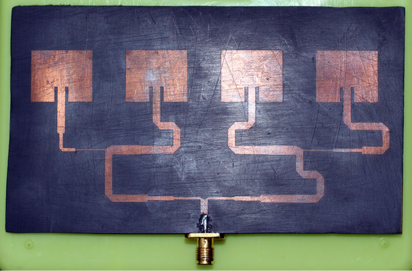
Figure 4. Photograph of the antenna array with corporate feed network.
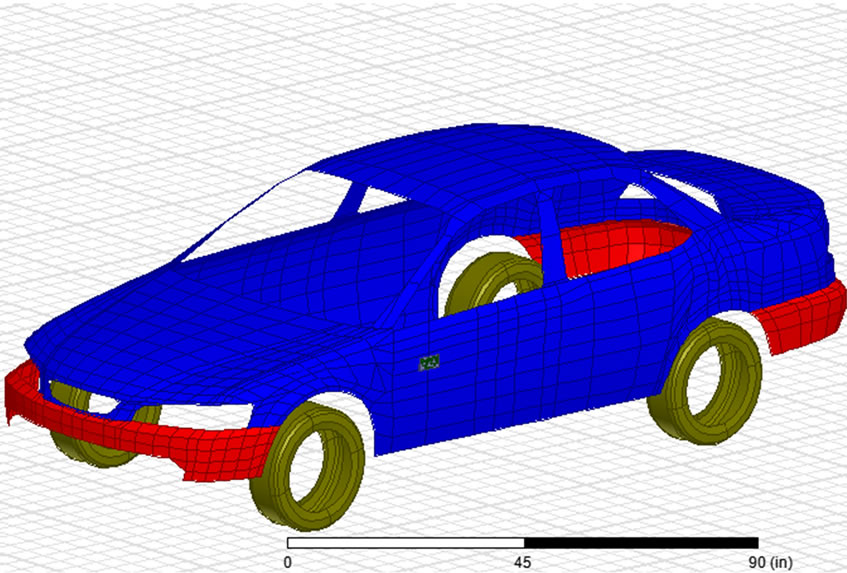
Figure 5. The entire structure of the car along with the antenna array.
characteristics of the antenna after placing it on the vehicle:
1) Spans a large computational domain compared to the wavelength;
2) Requires a fine grid resolution to resolve the detailed antenna structure;
3) Contains largely non-conformal PEC and dielectric structures.
4. Results and Discussion
For obtaining the scattering parameter characteristics, the microstrip antenna has been simulated over the frequency bandwidth ranging from 5.5 GHz to 6.5 GHz and two different circumstances is observed. The first experiments involve the design, simulation and measurement after fabrication of an individual element and then the array with the same without involving the effect of the car. Both of them should used for optimized performance.
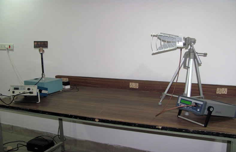
The scattering parameter is measured by Agilent Technology Vector Network Analyzer model no. N5320A (10 MHz - 20 GHz) and the radiation pattern is measured by Hittite HMC-T2100 synthesized signal generator (10 MHz - 20 GHz) and Krytar 9000 B power meter (10 MHz - 40 GHz) with 9530 B power sensor (10 MHz - 20 GHz) as shown in Figure 6. From Figure 7, it is found
 (a)
(a)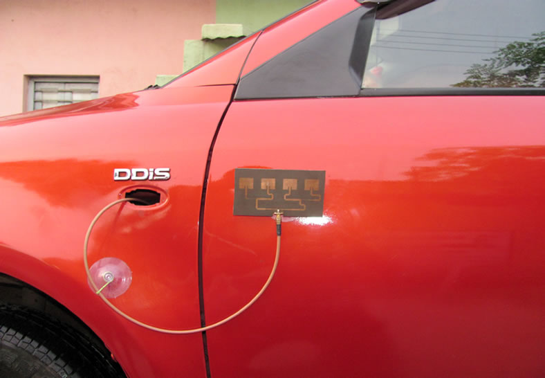 (b)
(b)
Figure 6. (a) Experimental set-up to measure the radiation pattern of the antenna array; (b) Experimental set-up to measure the radiation pattern of the antenna array after placing it on the car.
 (a)
(a)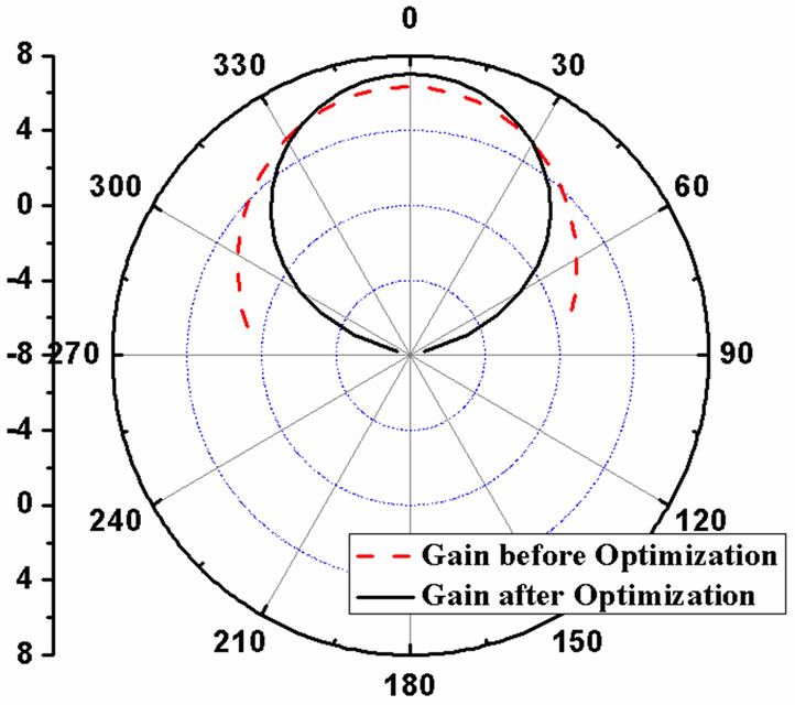 (b)
(b)
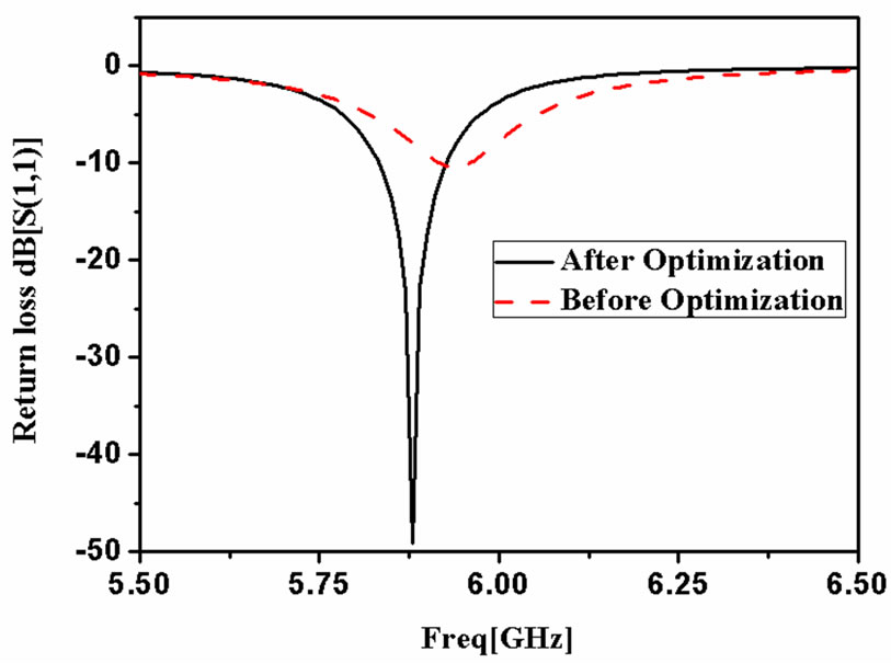
Figure 7. (a) Return loss a single patch before and after optimization; (b) Gain of a single patch before and after optimization.
that after optimization a perfect match is obtained exactly at 5.88 GHz and gain is also improved from 6.33 dB to 7.01 dB with a very good return loss of –47 dB. The current distribution and the radiation pattern of a single RMSA is portrayed in Figure 8.
A parametric study of the return loss of antenna array with different spacing between the elements of the corporate feed network is done and is compared in Figure 9. The results of the computational model of the entire antenna array with feed network were compared with the measured data and a good agreement is observed in Figure 10.
After getting the satisfactory results, next the same array antenna is experimented again with considering the electromagnetic effect of the car. In order to test the antenna array in association with the vehicle, a numerical model of the car is created using Ansoft HFSSTM and the simulated data is compared with the measured in Figure 11. Figure 12 graphically represents the 3D radiation pattern of the antenna array in presence of the computational model of the vehicle. From Figure 13, it is clear that the inside electric field strength is not more than 15 Volt per meter which is very less compare to the standard
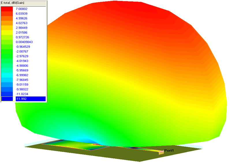
Figure 8. Current distribution and the radiation pattern of the rectangular microstrip antenna.
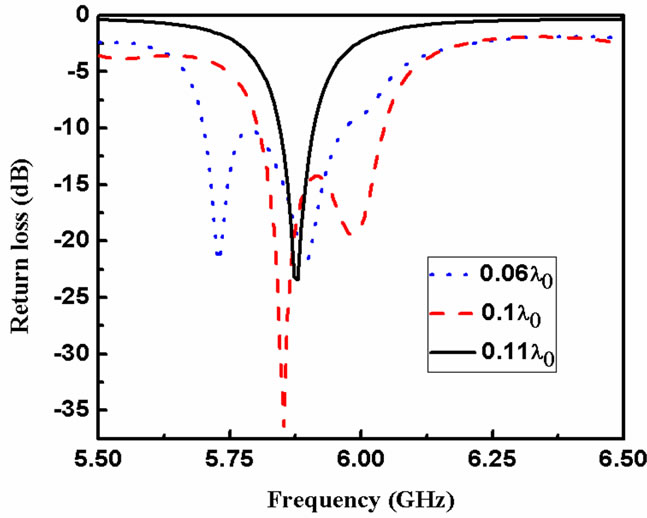
Figure 9. Parametric study of return loss of the antenna array with different spacing between the elements of corporate feed network.
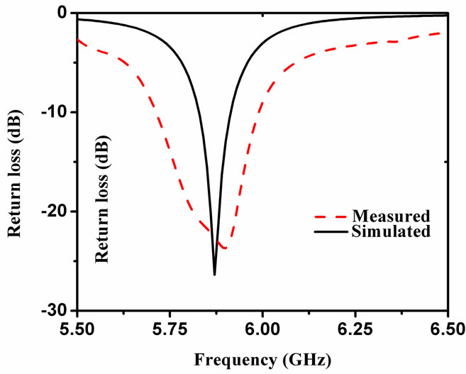 (a)
(a)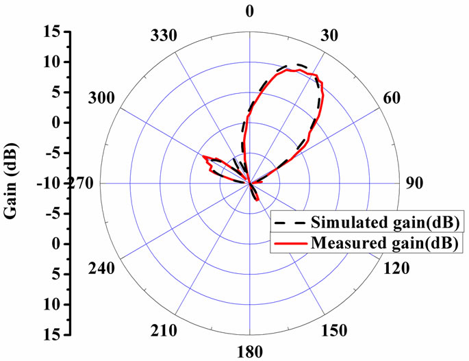 (b)
(b)
Figure 10. (a) Return loss of the antenna array; (b) Radiation pattern of the antenna array.
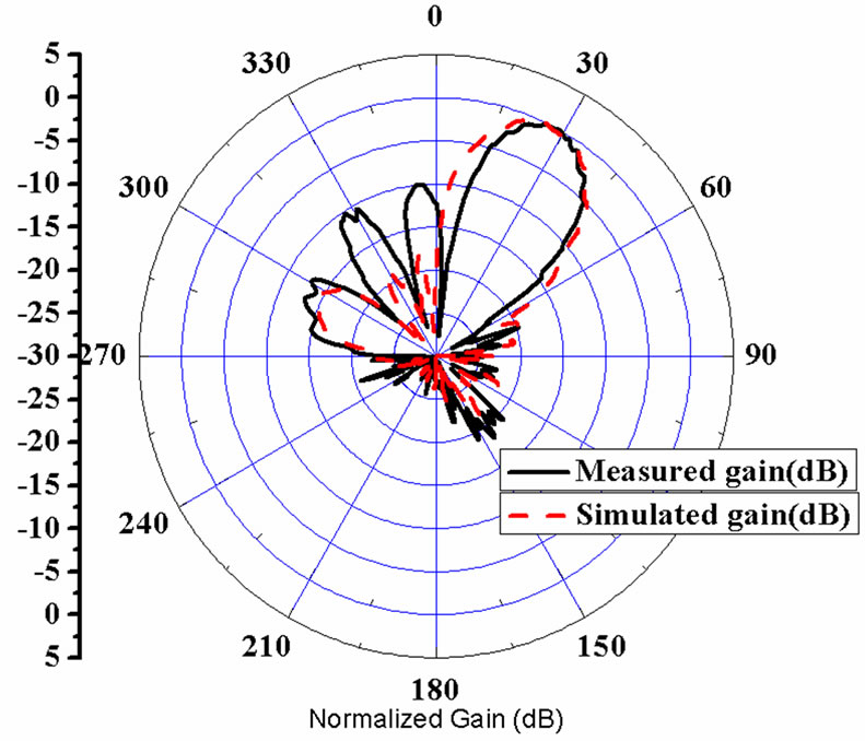
Figure 11. Normalized radiation pattern of the antenna array after placing it on the body of the car.
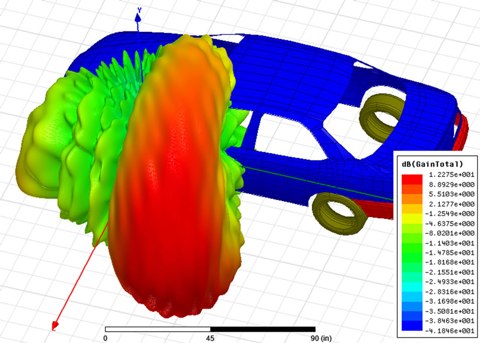
Figure 12. 3D radiation pattern of the antenna array after placing it on a vehicle body.
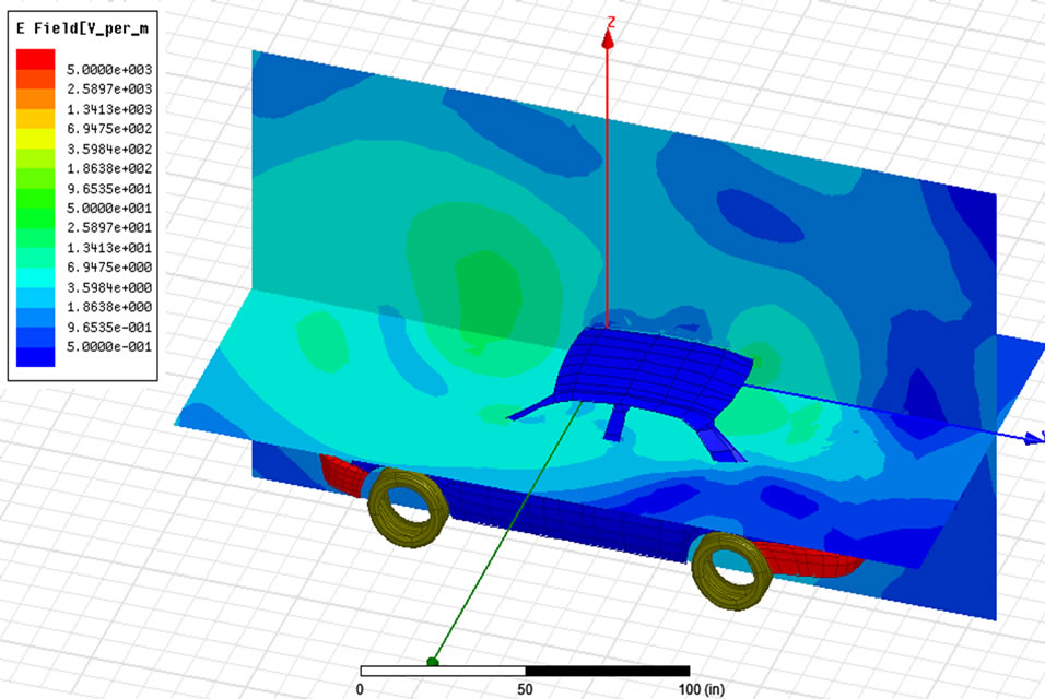
Figure 13. Inside electric field interference of the array after placing it on a vehicle body.
electromagnetic hazards.
5. Conclusion
A Tchebyscheff polynomial based microstrip phased array antenna is designed to detect the blind spot area of the intelligent mobile vehicle. The design is further simulated in Ansoft HFSSTM after placing the antenna on the body of the car and the results are observed. The result of the computational model of the entire antenna array is compared with the measured data before and after placing the said antenna array on the body of the car and found to be in good agreement. An overall 11 dB gain is obtained while measuring in the desired direction with minimum amount of electromagnetic interference inside the car.
REFERENCES
- M. Griffiths, “Intelligent Transport System,” Postnote: Parliamentary Office of Science and Technology, London, 2009. www.parliament.uk/paliamentary_offices/post/
- J. Kuwana and M. Itoh, “Dynamic Angling Side-View Mirror for Supporting Recognition of a Vehicle in the Blind Spot,” International Conference on Control, Automation and Systems, ICCAS, Seoul, 14-17 October 2008, pp. 2913-2918.
- S. Jeong, S.-W. Ban and M. H. Lee, “Autonomous Detector Using Saliency Map Model and Modified MeanShift Tracking for a Blind Spot Monitor in a Car,” Seventh International Conference on Machine Learning and Applications, San Diego, 11-13 December 2008, pp. 253- 258. doi:10.1109/ICMLA.2008.129
- B.-F. Wu, C.-C. Kao, Y.-F. Li and M.-Y. Tsai, “A RealTime Embedded Blind Spot Safety Assistance System,” International Journal of Vehicular Technology, Vol. 2012, 2012, pp. 1-15. doi:10.1155/2012/506235
- A. Tang and A. Yip, “Collision Avoidance Timing Analysis of DSRC-Based Vehicles,” Accident Analysis & Prevention, Vol. 42, No. 1, 2010, pp. 182-195. doi:10.1016/j.aap.2009.07.019
- T. Mondal, J. S. Roy and S. R. Bhadra Chaudhuri, “Phased Array Antenna Design for Intelligent Transport Systems,” IEEE International Workshop on Antenna Technology: Small Antennas and Novel Metamaterial (iWAT), Santa Monica, 2-4 March 2009, pp. 1-4.
- T. Mondal, R. Ghatak and S. R. B. Chaudhuri, “Design and Analysis of a 5.88GHz Microstrip Phased Array Antenna for Intelligent Transport Systems,” IEEE International Sumposium on Antennas and Propagation and CNC/ USNC/URSI Radio Science Meeting, Toronto, 11-17 July 2010, pp. 1-4.
- H. J. Visser, “Array and Phased Array Antenna Basics,” John Wiley & Sons Ltd., Chichester, 2005. doi:10.1002/0470871199
- E. Levine, G. Malamud, S. Shtrikman and D. Treves, “A Study of Microstrip Array Antennas with the Feed Network,” IEEE Transactions on Antennas and Propagation, Vol. 31, No. 4, 1989, pp. 426-434. doi:10.1109/8.24162