Journal of Electromagnetic Analysis and Applications
Vol.4 No.1(2012), Article ID:17149,9 pages DOI:10.4236/jemaa.2012.41004
Comparing the Quality of Power Generated from DFIG with Different Types of Rotor Converters
![]()
Power Electronics and Energy Conversion Department, Electronics Research Institute, Cairo, Egypt.
Email: eskander@eri.sci.eg
Received November 2nd, 2011; revised December 5th, 2011; accepted December 12th, 2011
Keywords: Double Fed Induction Generator; Universal Converter; 2-Level Bridge Converter; 3-Level Bridge Converter
ABSTRACT
In this paper the quality of power generated from wind energy conversion system employing a double fed induction generator (DFIG) is investigated. The DFIG performance is tested with 3 types of converters interfacing the rotor with the grid. These are: the six-step thyristor inverter with diode rectifier, six-step IGBT inverter with diode rectifier, and 3-level IGBT-PWM inverter with diode rectifier. The harmonics in current and voltage, power factor value, and the transient behavior in each system are investigated and compared. Comparison is done at sub-and super-synchronous DFIG operational speed. In the system with lowest power quality passive filters or LC filter are added and improvement in system performance is recorded. From this study the optimum system from point of view of cost and control complexity is concluded.
1. Introduction
In the last five years, a new technology has been developed in the wind power market introducing variablespeed working conditions depending on the wind speed in order to optimize the energy captured from the wind. The advantages of variable-speed wind turbines (VSWT) are that their annual energy capture is about 5% greater than the fixed-speed technology, and that the active and reactive powers generated can be easily controlled. As a disadvantage, VSWT need a power converter that increases the system cost. However, if double fed induction generator (DFIG) is used with VSWT, the overall cost of the power electronics is reduced because the rating of the converters interfacing the rotor with the grid, as shown in Figure 1, was proven to be only 10% of the DFIG rating [1].
When the wind speed changes, the rotor speed will change, and hence the rotor injection frequency should also be adjusted. A key requirement of a DFIG is to have its three-phase rotor circuit injected with a voltage at a controllable frequency and controllable magnitude. This three-phase ac voltage can be synthesized using various switching techniques, including six-step switching [2], pulsewidth modulation (PWM) [3], and space vector PWM [4].
In this paper the performance of the DFIG with three inverter techniques feeding the rotor circuit is investigated. These are the six-step switching thyristor inverter; the six-step switching inverter with passive filter, the six-step switching IGBT inverter, and the 12-pulse IGBT PWM inverter.
The DFIG generation systems for each of the 3 types of converters is modeled and simulated giving the active and reactive power, the power factor, the stator voltage and current harmonics, and the systems’ transient behavior. These results are obtained at both sub and supersynchronous speeds, since the double fed induction machine is known for its operation as a generator even at sub-synchronous speed at specific values of injected rotor voltage magnitude and phase angle [1,5-7]. Results are compared and conclusion of optimum system trading off control complexity and cost is given.
A PID controller is tuned for each system to allow the DFIG to follow the wind speed in order to extract maximum power available from wind.
2. Super Synchronous Operation of DFIG
The performance of DFIG with the 3 types of inverters is investigated at speed of 190 rad/sec (slip = –0.11).
2.1. DFIG with Six Step Switching Thyristor Inverter
While PWM technique is widely used for rotor injection
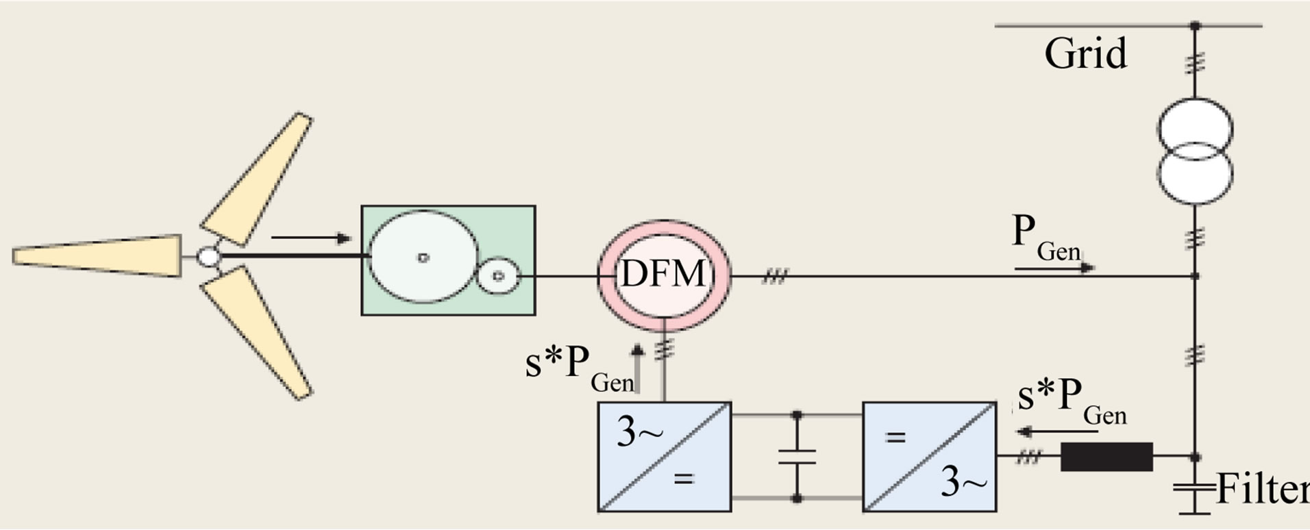
Figure 1. Doubly fed induction generator in wind energy conversion system.
[1], a six-step switching technique is another method to simplify the control circuit and reduce the switching losses. Six-step switching introduces 6n ± 1 harmonics in the voltages and the resultant output is a quasi-sine waveform. Unlike PWM, this does not need sine and triangular waves. It is easy to adjust the rotor injection frequency by simply varying a control voltage. The output line voltage of the inverter is a quasi-sine wave with levels 0, VB, and −VB as shown in Figure 2.
For the quasi-sine waveforms of Figure 2, triple-n harmonics (3, 6, 9, 15, …) are absent. The voltage waveform in phase A can be expressed in the mathematical form as [2]
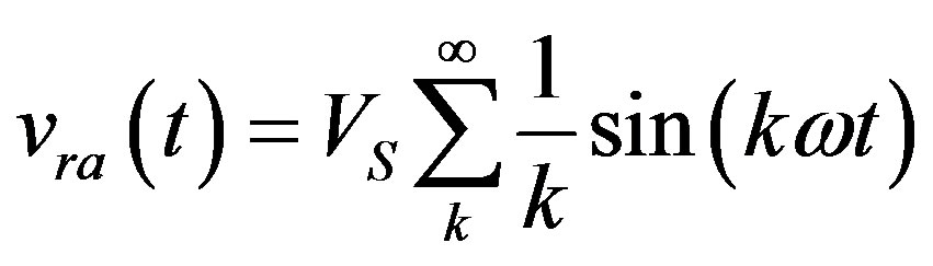 (1)
(1)
where k = 1, 5, 7, …and VS = (2/π)VB.
In a DFIG with quasi-sine rotor injection, the harmonics in stator currents and electromagnetic torque are dependent on the injected frequencies. The steady torques are developed by the reaction of harmonic air gap fluxes with harmonic rotor currents, of the same order. While the pulsating torque components, are produced by the reaction of harmonic rotor currents with harmonic rotating fluxes of different order. The steady torque can be expressed in current space vector as:
 (2)
(2)
where k = 1, 5, 7, 9, 11, …, . The q-d variables are referred to the rotating reference frame with the same speed as the frequency of the stator harmonic component.
Figures 3 and 4 show the output stator voltage & current with their harmonic content. In Figure 4, the stator current reaches stability after 0.06 sec and the value of harmonic 1.18%. Figures 5 and 6, show the system power factor and output active & reactive power (P, Q). The value of PF is nearly 0.9.
2.2. Six Step Switching Thyristor Inverter with LC Filters
Due to the poor power quality obtained with this inverter, simulation is repeated with LC filter placed at stator side.
Figures 7 and 8 show the output stator voltage & current with their harmonic content. It is clear that the value of harmonic increases compared to DFIG with six-step switching thyristor inverter. Hence multi-stage passive filter is suggested. Figures 9 and 10, show the system power factor and output active & reactive power (P, Q), which are also distorted.
2.3. Six Step Switching Thyristor Inverter with Passive Filters
Due to the poor power quality obtained with this inverter, simulation is repeated with 3-phase passive filter shown

Figure 2. 6-step inverter output voltage.


Figure 3. Stator voltage and its harmonic content for six step switching thyristor inverter.


Figure 4. Stator current and its harmonic content for six step switching thyristor inverter.

Figure 5. System power factor for six step switching thyristor inverter.
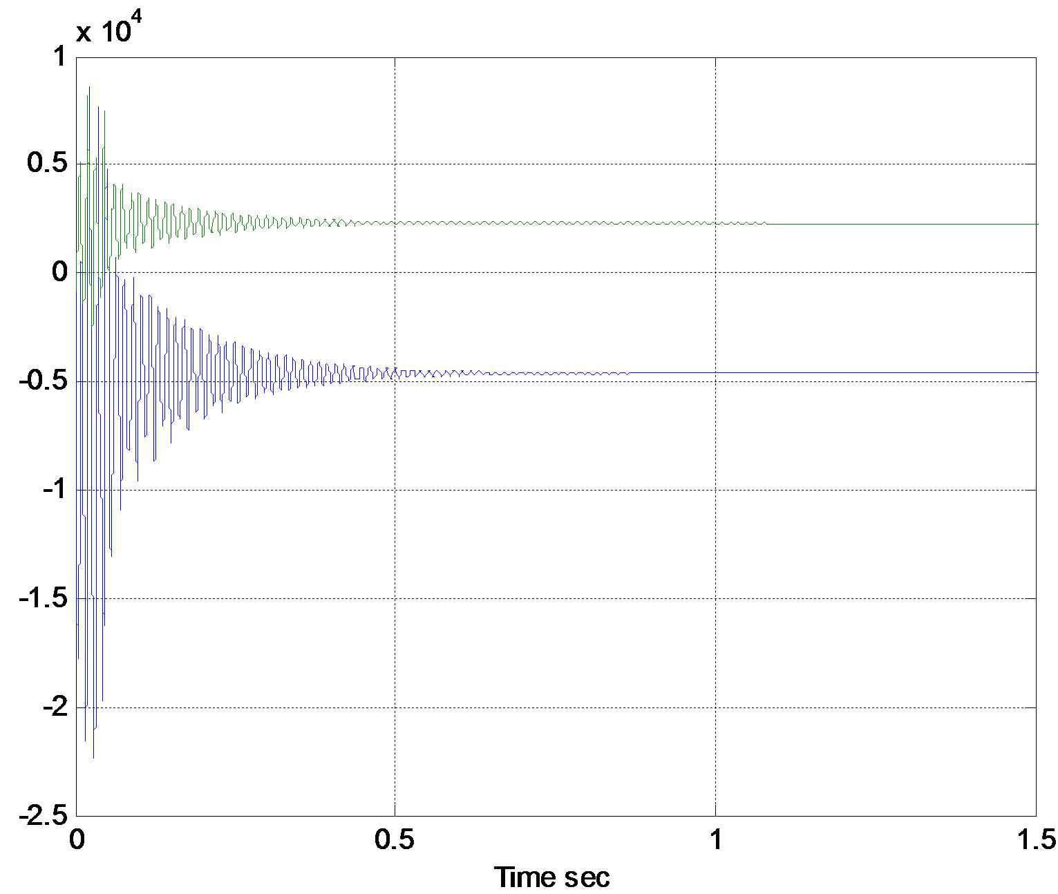
Figure 6. System active and reactive power for six step switching thyristor inverter.
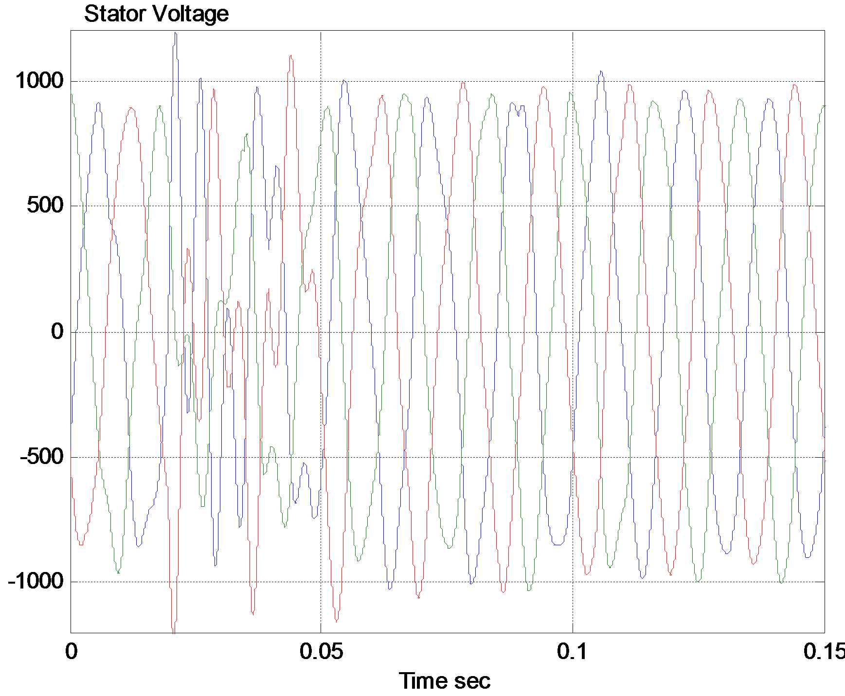
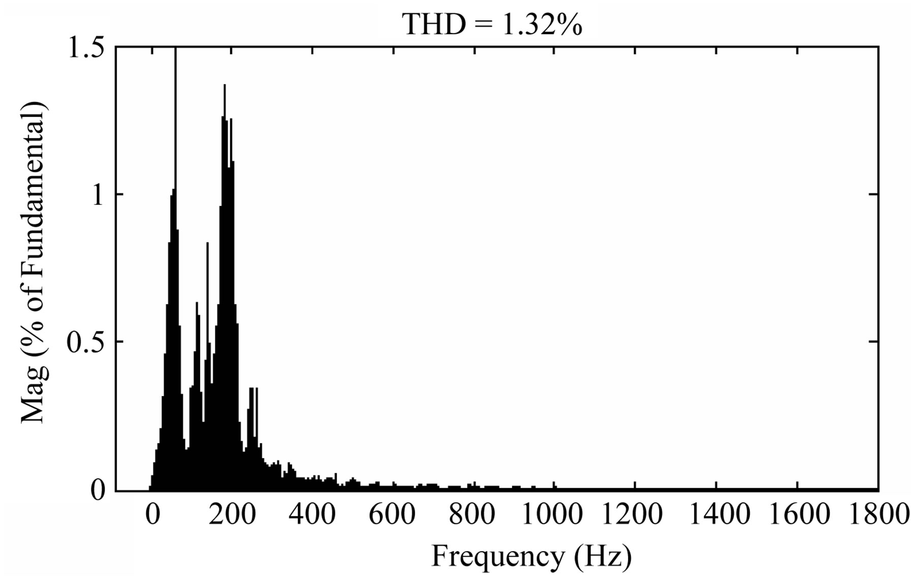
Figure 7. Stator VS & harmonic content with LC filter.


Figure 8. Stator current and harmonic content with LC filter.

Figure 9. Power factor with LC filter.

Figure 10. System P & Q with LC filter.
in Figure 11 placed at stator side.
Figures 12 and 13 show the output stator voltage & current with their harmonic content. It is clear that the value of harmonic decreases compared to DFIG with six-step switching thyristor inverter Figures 14 and 15 show the system power factor and output active & reactive power (P, Q), giving better performance than previous LC filter.
2.4. DFIG with Six Step Switching IGBT Inverter
Applying the 6-step switching technique to the inverter composed of 6 IGBT’S resulted in distorted stator voltage and current as shown by their harmonic contents in Figures 16 and 17. In these figures, it is clear that the harmonics of stator voltage and current increased than when using thyristors. Another drawback is the longer time taken to reach steady state. Also high overshoots takes place at starting in power curves shown in Figure 18.
2.5. DFIG with 3-Level Inverter
Applying 3 level inverter (12 IGBT) to the rotor circuit leads to better power quality than previous inverter types. This is obvious by the lower THD in stator voltage and

Figure 11. 3-phase AC passive filter.
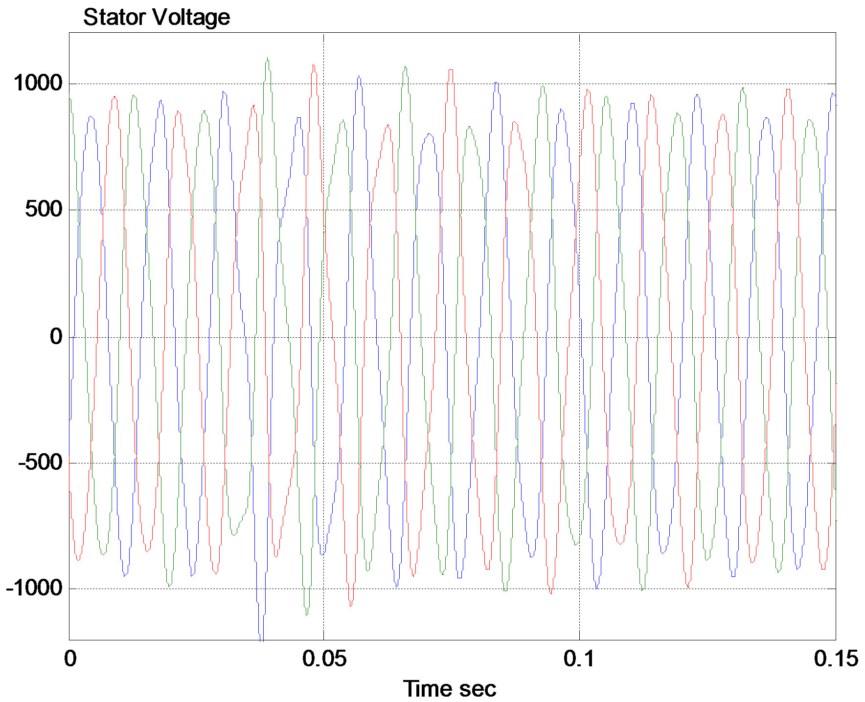
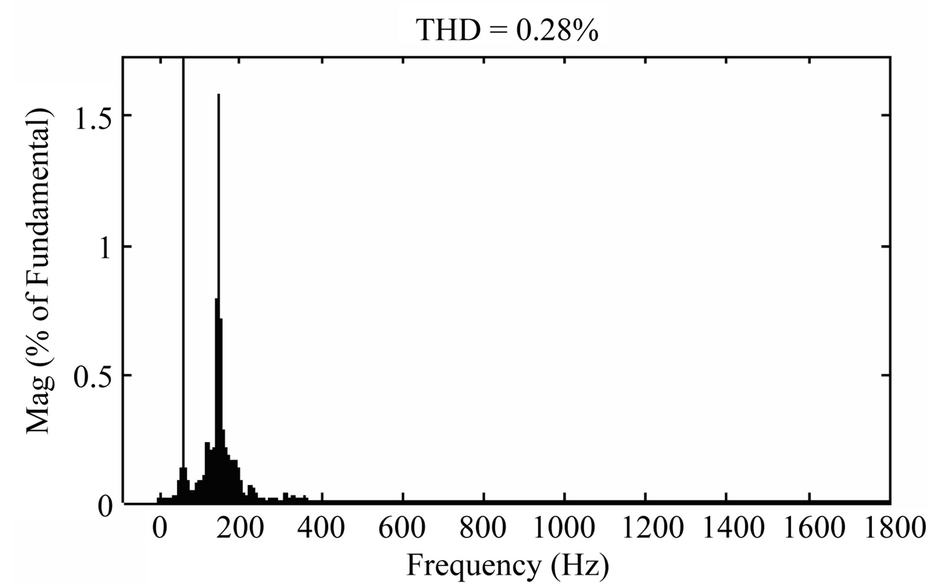
Figure 12. Stator VS & harmonic content with passive filter.
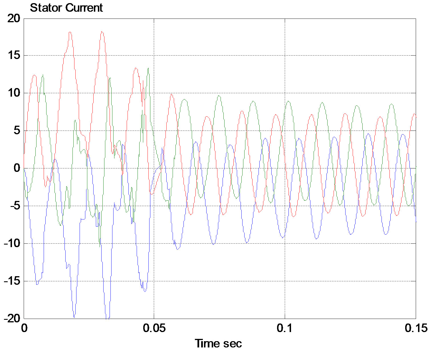
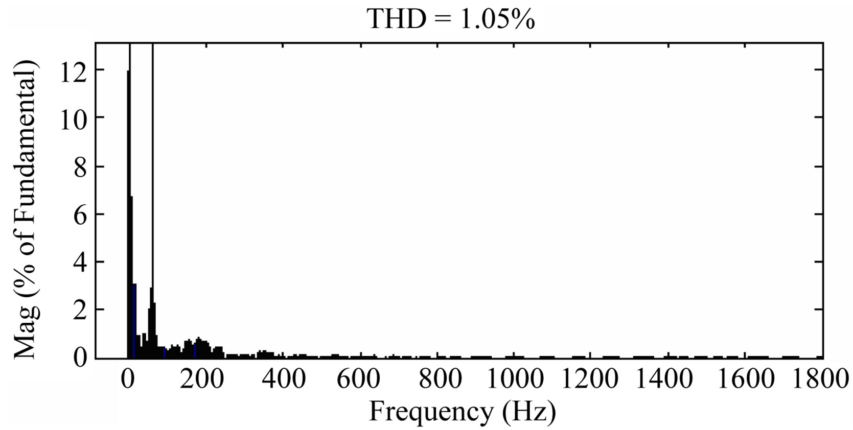
Figure 13. Stator current and harmonic content with passive filter.
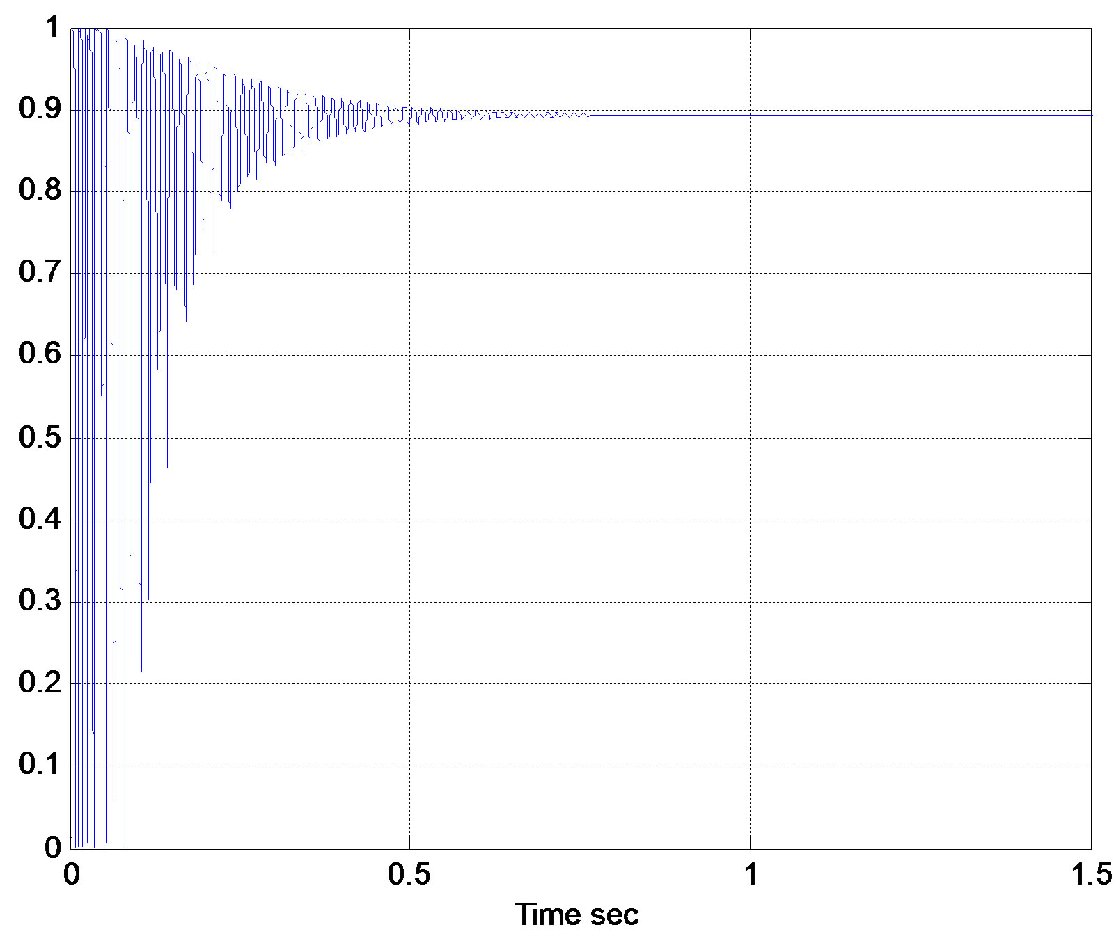
Figure 14. Power factor with passive filter.

Figure 15. System P & Q with passive filter.


Figure 16. Stator voltage and its harmonic content for six step switching IGBT inverter.
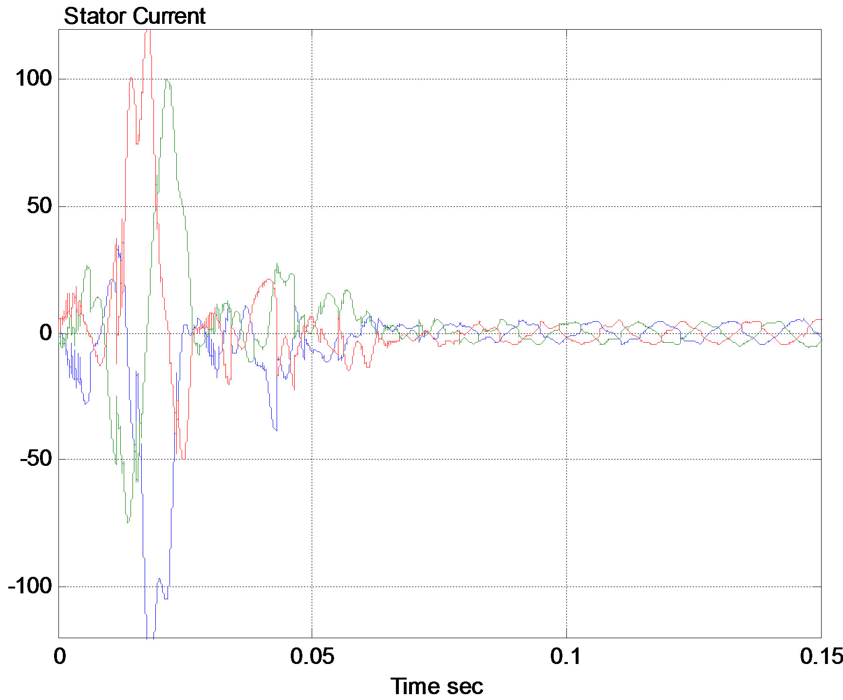

Figure 17. Stator current and its harmonic content for six step switching IGBT inverter.
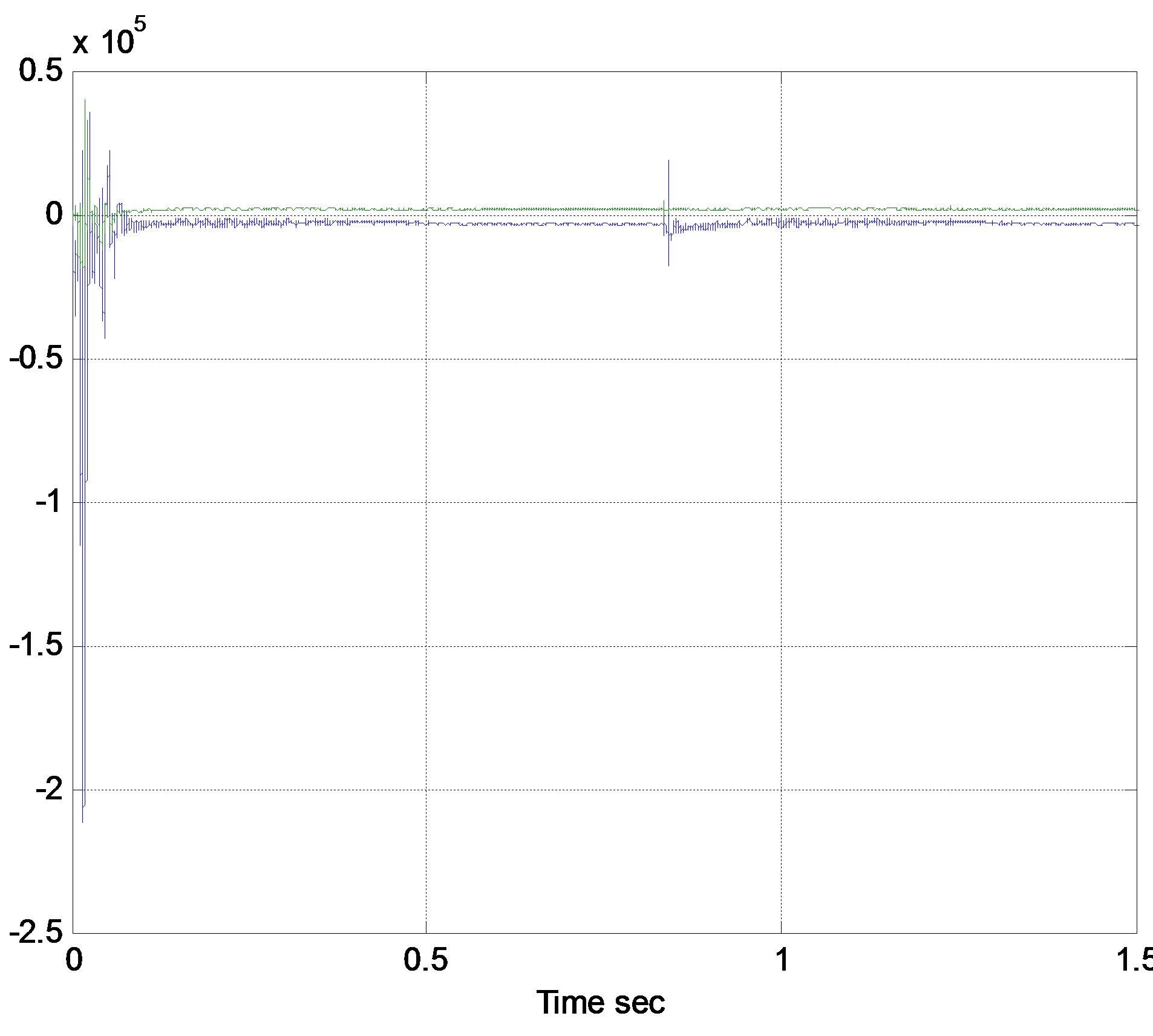
Figure 18. System active & reactive power for six step switching IGBT inverter.
currents shown in Figures 19 and 20. In these figures, the THD in stator current decreased to 0.14%, while it is only 0.1% in stator voltage. It is also clear from the fast transient response of the system power factor, and active & reactive power shown in Figures 21 and 22 respectively. In these figures the time taken to reach steady state is 0.15 sec, which is much lower than previously considered inverters.
3. Discussion of Results at Super-Synchronous Speed
From Table 1 it is clear that the 3 level inverter led to lower voltage and current harmonics. However the time for transient settling is better for the 6-step IGBT inverter. Also the overshot is minimum in case of 6-step switching thyristor inverter, and maximum when using IGBT.
4. DFIG Performance at Sub-Synchronous Speed
The performance of DFIG with the 3 types of inverters is investigated at speed of 185 rad./sec (slip = 0.11).
4.1. DFIG with Six Step Switching Thyristor Inverter
The harmonic content of stator voltage and stator current shown in Figures 23 and 24 respectively reveals the lower harmonics when operating the DFIG at sub-synchronous speed. The THD of voltage decreased from 0.31% to 0.18%, while THD of current decreased from 1.18% to 0.64%. This is roughly a 45% decrease in harmonics.
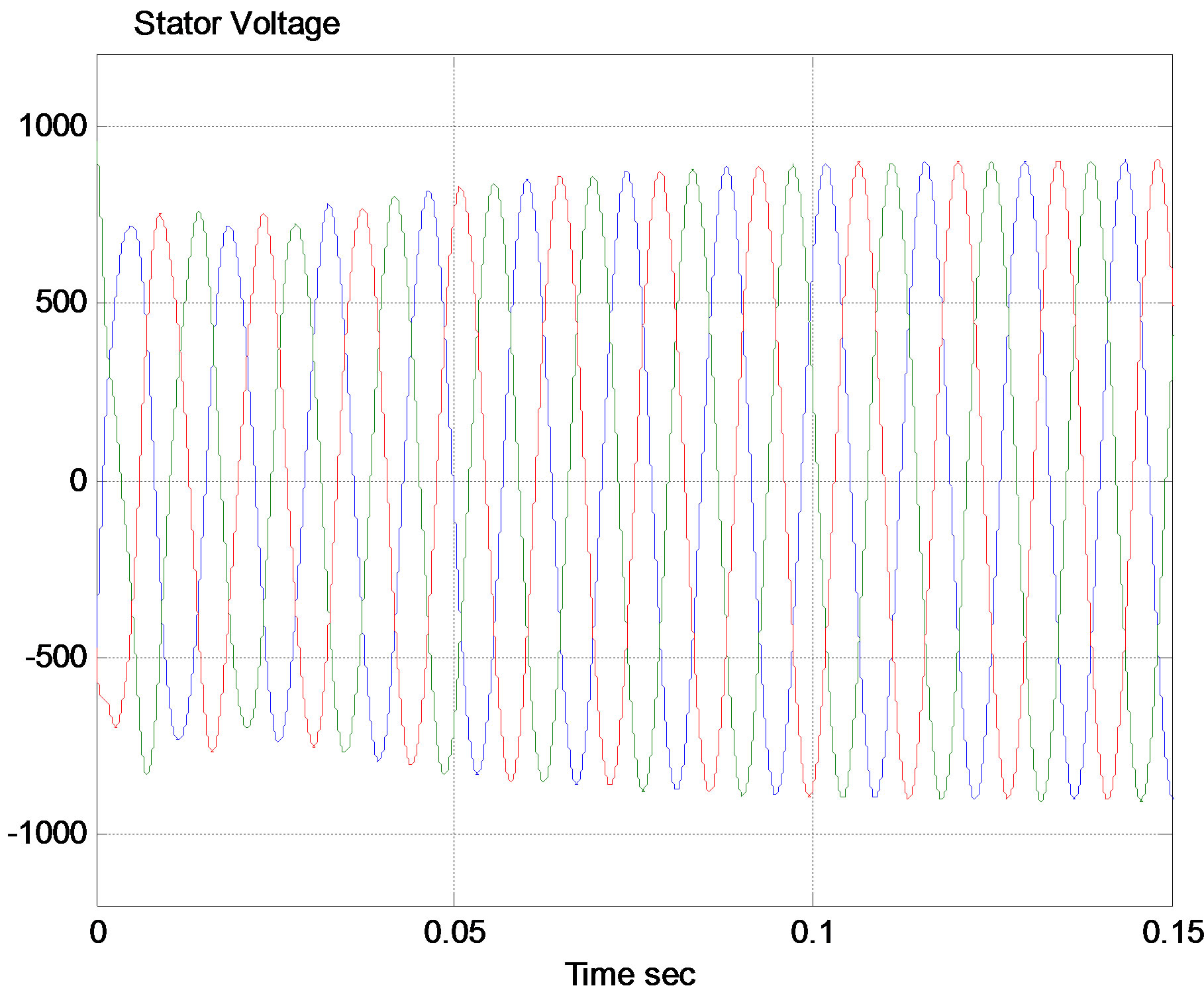
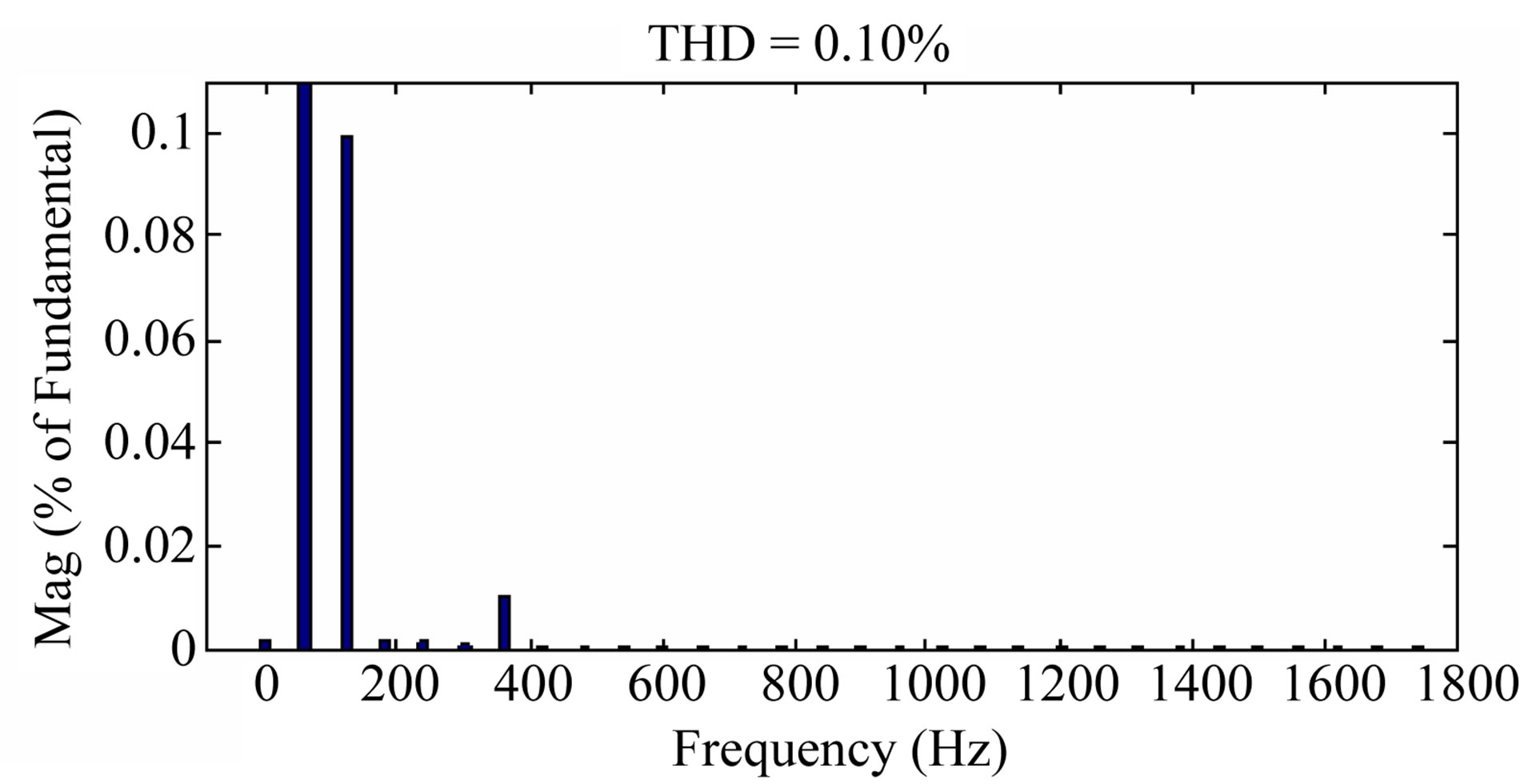
Figure 19. Stator voltage and its harmonic content for 3- level inverter.
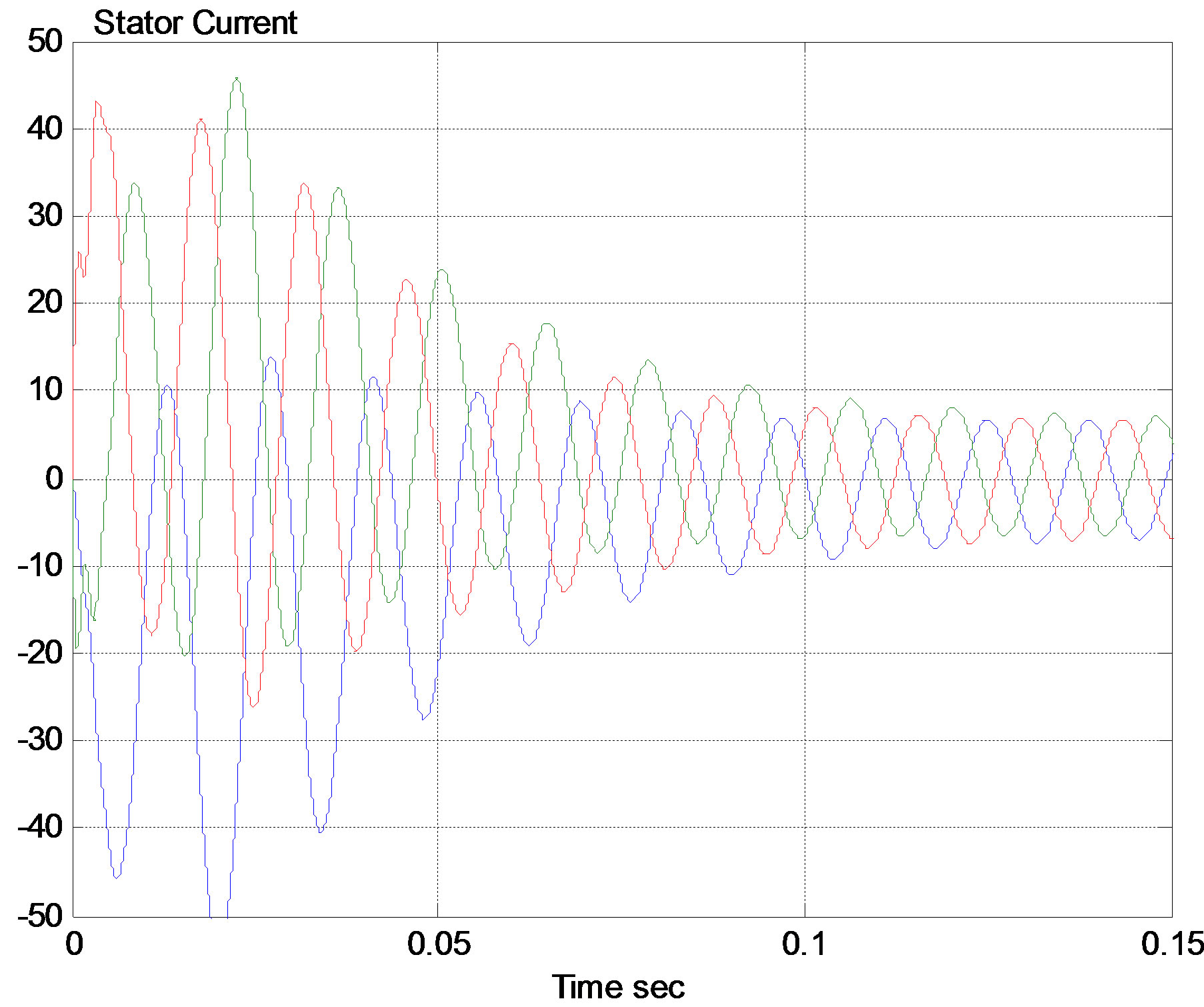
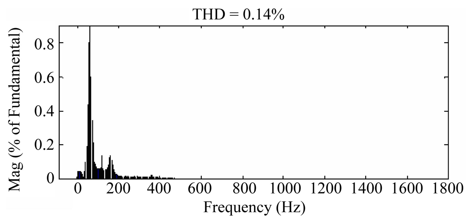
Figure 20. Stator current and its harmonic content for 3- level inverter.
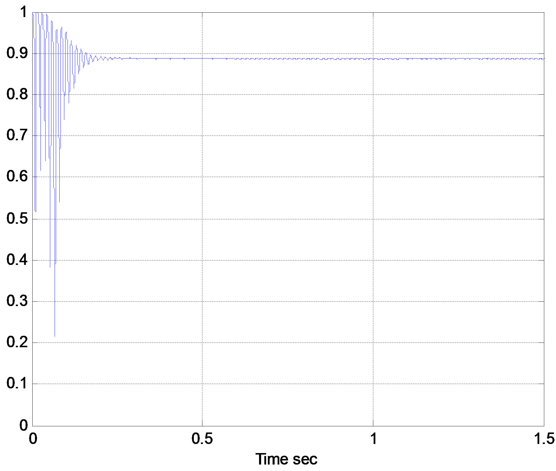
Figure 21. Power factor for 3-level inverter.

Figure 22. System active & reactive power for 3-level inverter.
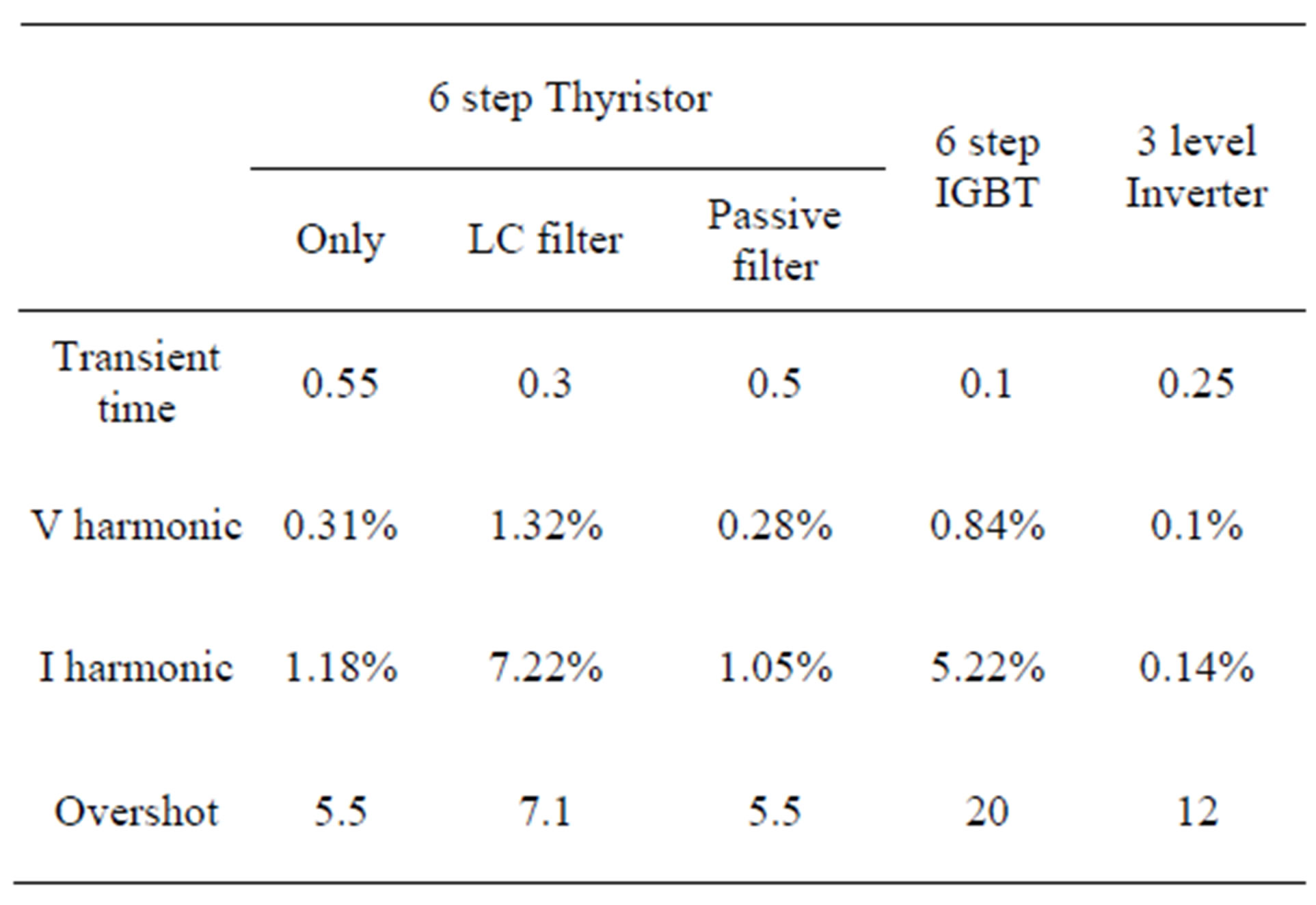
Table 1. Comparing between systems at super-synchronous speed.

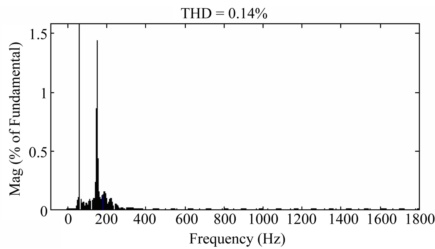
Figure 23. Stator voltage and its harmonic content for six step switching thyristor inverter.
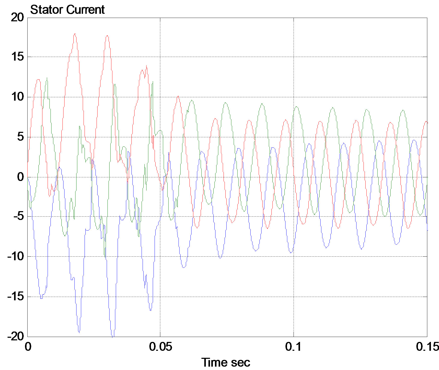
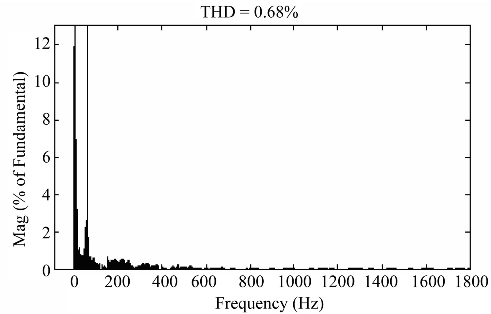
Figure 24. Stator current and its harmonic content for six step switching thyristor inverter.
4.2. DFIG with Six Step Switching IGBT Inverter
The harmonic content of stator voltage and stator current shown in Figures 25 and 26 respectively reveals the lower harmonics when operating the DFIG at sub-synchronous speed. The THD of voltage decreased from 0.84% to 0.42%, while THD of current decreased from 5.82% to 3.42%. This is roughly a 50% decrease in harmonics
4.3. DFIG with 3-Level Inverter
The harmonic content of stator voltage shown in Figure 27 reveals again the lower harmonics when operating the DFIG at sub-synchronous speed. The THD of voltage decreased from 0.14% to 0.07%, which is a 50% decrease in harmonics contents. However the harmonic content of stator current shown in Figure 28 increased.
From Table 2 it is clear that at sub-synchronous speed, the 3 level inverter led to lower voltage and current harmonics. As well as minimum time for transient settling.
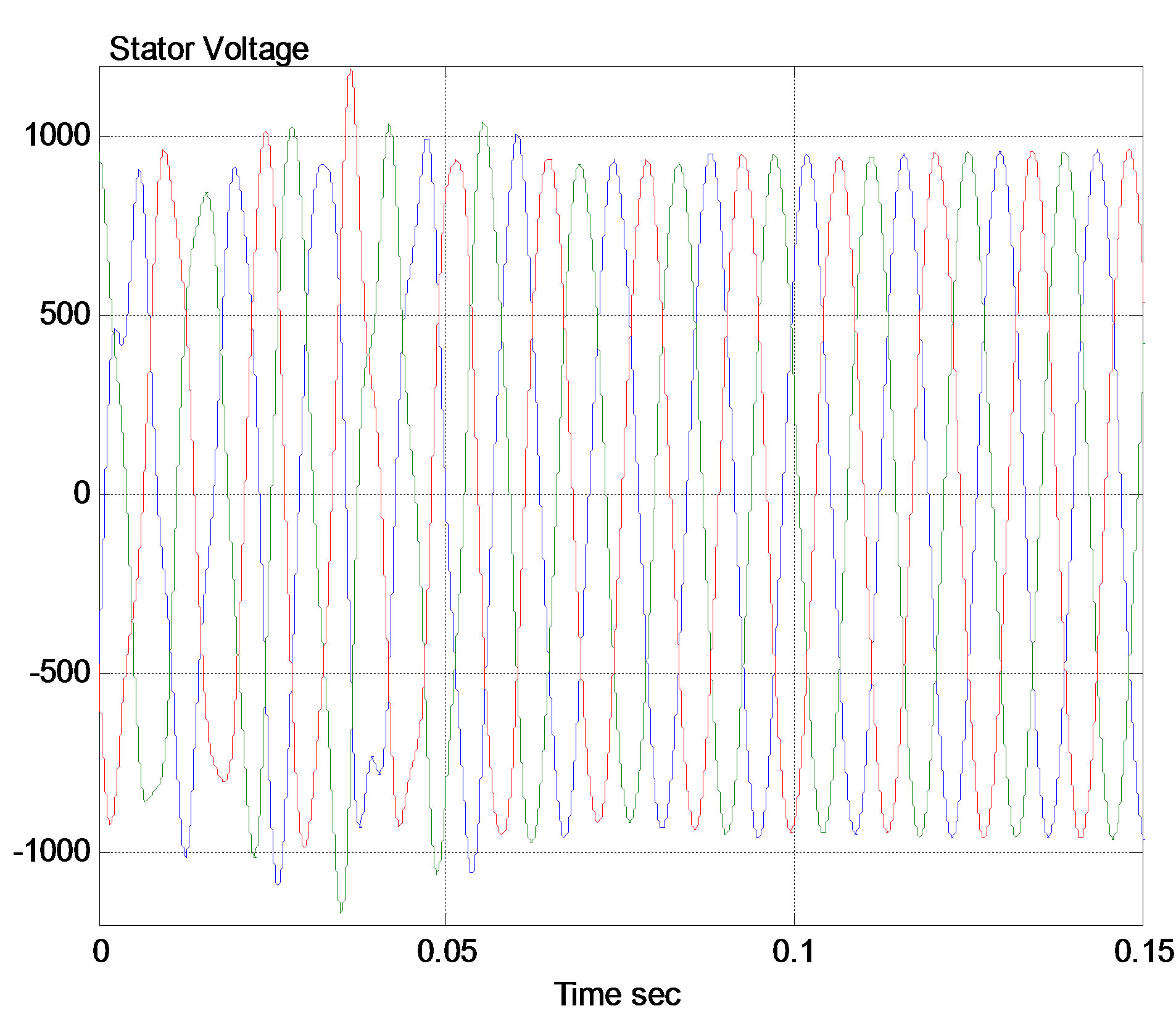

Figure 25. Stator voltage and its harmonic content for six step switching IGBT inverter.

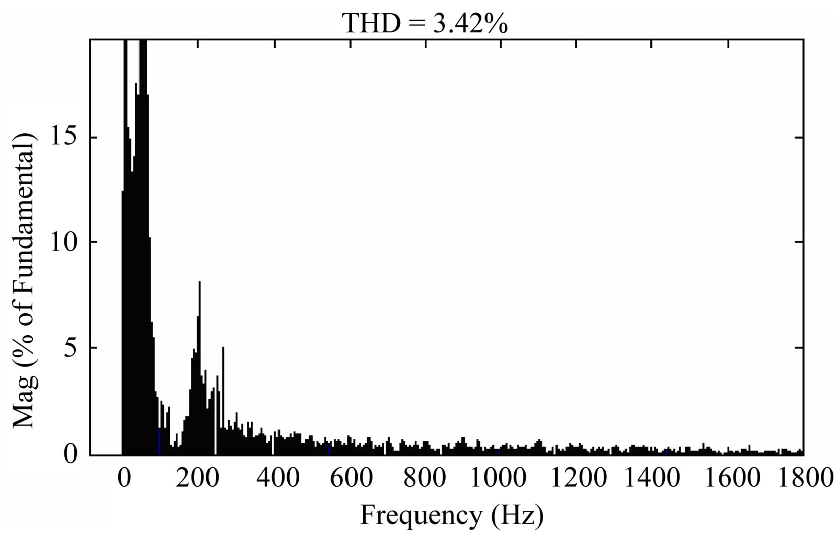
Figure 26. Stator current and its harmonic content for six step switching IGBT inverter.
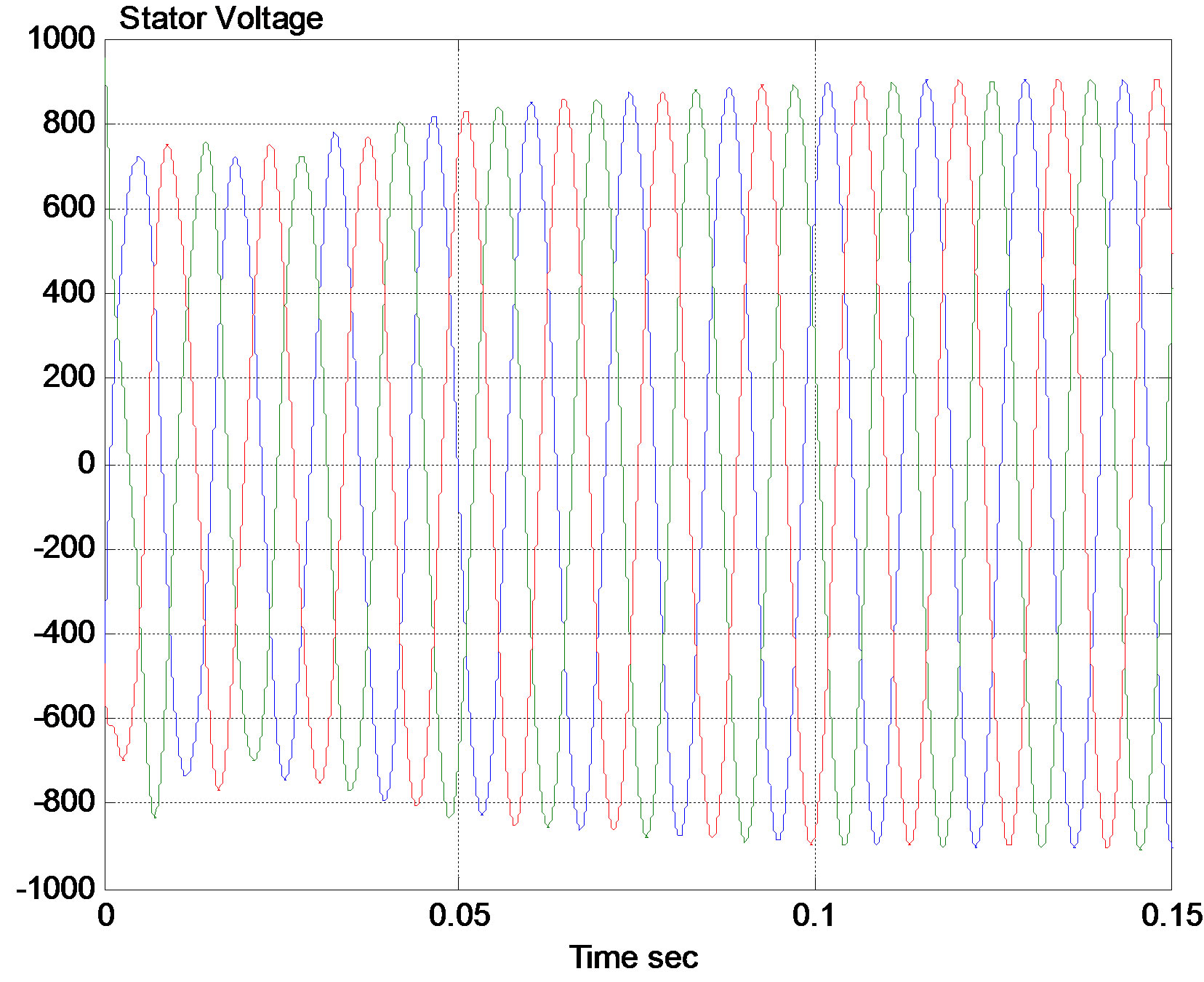
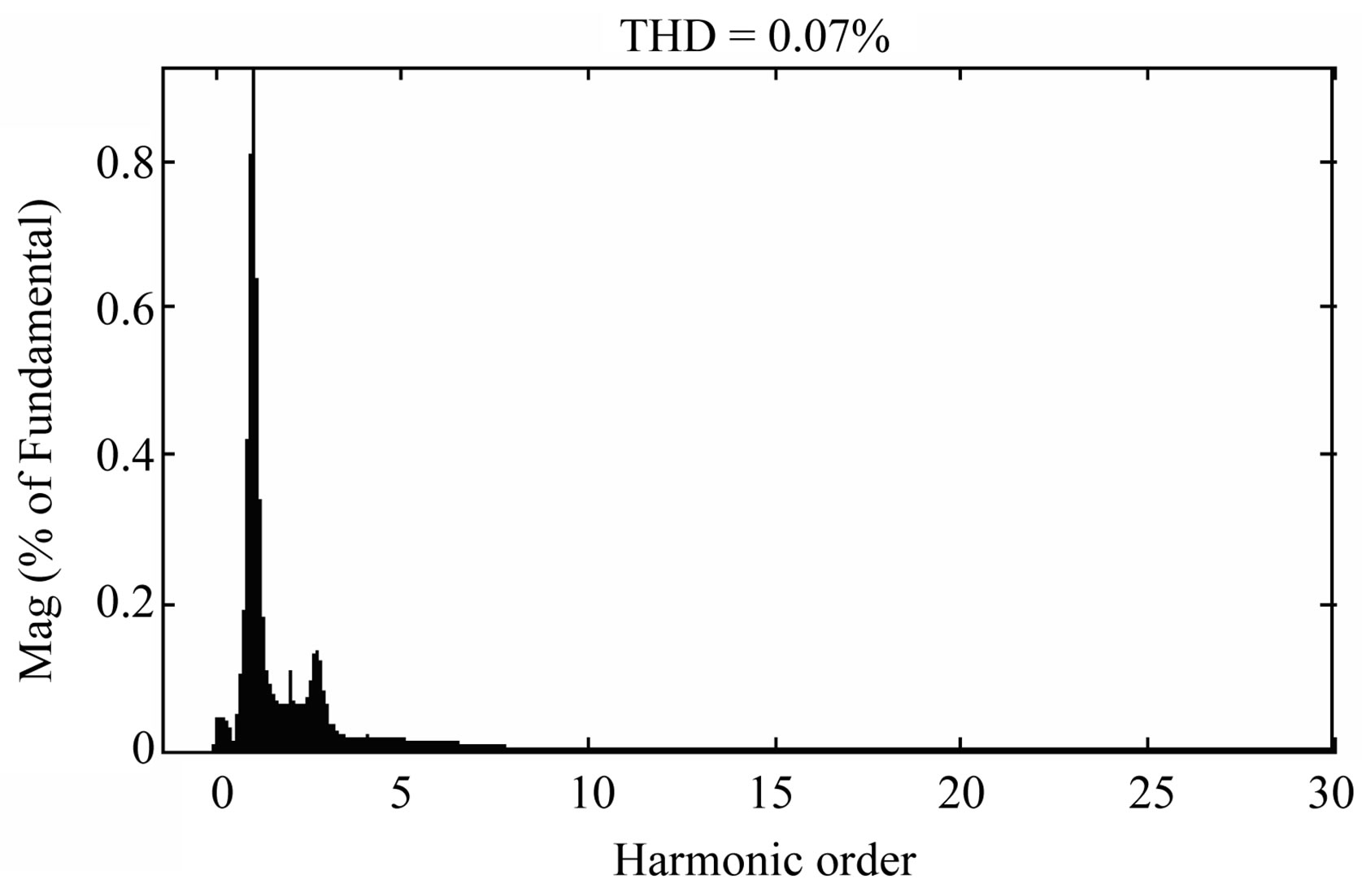
Figure 27. Stator voltage and its harmonic content for 3-level inverter.


Figure 28. Stator current and its harmonic content for 3- level inverter.

Table 2. Comparing between systems at sub-synchronous speed.
5. Conclusions
The performance of DFIG with 3 types of rotor inverters; 6-step thyristor inverter, six-step IGBT inverter, and 3-level PWM inverter is investigated at suband super-synchronous speeds. The voltage harmonics, current harmonics, system power factor, active power, reactive power, and transient time for these cases are compared. Results revealed the better quality of power generated at sub-synchronous operational speed, where the harmonic contents decreased by roughly 45% than case of super-synchronous speed for 3 inverter types. In general, comparing performances showed that the higher harmonic contents occur with the six-step IGBT inverter, which is due to low switching frequency in the rotor circuit. Applying an LC filter to the 6-step thyristor inverter did not improve its performance. However, applying a 3 phase filter to the 6-step thyristor inverter decreased voltage and current THD by only 10%. The lower harmonics contents took place with the 3-level IGBT-PWM inverter while transient time was not minimum in case of super-synchronous operation.
The power factor is approximately the same for all cases. The oscillation damping time for voltage, current, and power is minimum for 3-level inverter (about 50% of transient time for other types). However the peak value of transient current and voltage are higher for 3-level inverter.
These results recommend operating the DFIG at subsynchronous speeds, where lower wind speeds can be utilized, using the six-step thyristor inverter with passive filter. This leads to decrease cost and control complexity. Operation at sub-synchronous speed does not degrade the DFIG. On the contrary it is beneficial in sites with low wind speeds where the DFIG cannot be operated at super-synchronous speed.
REFERENCES
- M. A. Saleh and M. N. Eskander, “Sizing of Converters Interfacing the Rotor of Wind Driven DFIG to the Power Grid,” Journal of Smart Grid and Renewable Energy, Vol. 2, No. 3, 2011, pp. 300-304.
- J. Murphy and F. Turnbull, “Power Electronics Control of AC Motors,” Pergamon, New York, 1988.
- S. Muller, M. Deicke and R. W. D. Doncker, “Doubly Fed Induction Generator Systems for Wind Turbine,” IEEE Industry Applications Magazine, Vol. 8, No. 3, 2002, pp. 26-33. doi:10.1109/2943.999610
- N. Mohan, “First Course on Power Electronics,” MNPERE/ Prentice-Hall, Englewood Cliffs, 2005.
- M. N. Eskander, M. A. Saleh and M. T. El-Hagry, “Performance of Double Fed Induction Machine at Sub-and Super-Synchronous Speed in Wind Energy Conversion System,” Journal of Power Electronics, Vol. 9, No.4, 2009, pp. 575-582
- M. A. Saleh and M. N. Eskander, “Sizing of Converters Interfacing the Rotor of Wind Driven DFIG to the Power Grid,” Smart Grid and Renewable Energy, Vol. 2, 2011, pp. 300-304.
- M. A. Saleh and M. N. Eskander, “Sub-Synchronous Range of Operation for a Wind Driven Double-Fed Induction Generator,” Journal of Power Electronics, Vol. 10, No. 1, 2010, pp. 72-78.