Journal of Electromagnetic Analysis and Applications
Vol. 3 No. 3 (2011) , Article ID: 4397 , 7 pages DOI:10.4236/jemaa.2011.33016
A New Type Power Converter and Its Application Prospect in Industry
![]()
1School of Electrical & Electronic Engineering, East China Jiaotong University, Nanchang, China; 2School of Electrical Engineering & Information, Anhui University of Technology, Maanshan, China.
Email: ecjtumotor@hotmail.com
Received January 21st, 2011; revised January 28th, 2011; accepted March 14th, 2011.
Keywords: Power Converter, SLH, Performances, Nonlinear Loads, Industry.
ABSTRACT
A new type power conversion mode is structured by combining switch power conversion mode with linear amplification mode, so as to acquire their integrated optimal performances. The theoretical analyses and experimental results are presented in this paper. They are proved that the new type converter can match many kinds of loads, including nonlinear loads, with strong robustness, good waveforms and high efficiency. Its application prospect in industry can be expected, particularly for the conditions where serious static and dynamic performances are required.
1. Introduction
In some special applications and scientific researches domain, bulky low efficiency linear supplies are still operating due to its excellent performances such as high stability, accuracy and strong robustness, which is hard to be replaced by smart switch power supplies. Is there any way to change this situation? The answer is positive. This paper introduces a new power converter neither same as those of linear amplifiers nor same as those of switch converters, which combines both of them in topologies, at the same time, acquires the trade-off merits of them. Hence the novel converter is named after Switch-Linear-Hybrid (SLH) power converter [1], which is very different from [2]. Although it aims at the same purpose as the present paper, also to hybridize switch mode and linear mode conversion.
2. Initial Idea and Simulated Experiment
2.1. Initial Idea
The creation purpose is to find a new conversion way which could keep the excellent performances just similar to those of linear amplifiers, but the efficiency and volume could be similar to those of switch mode power converters. Here performances are the essential problem, so the idea is still based on linear amplifier. If the low efficiency problem of linear amplifiers can be solved, maybe a satisfactory result would be expected.
It would be better to analyze the reason why linear amplifiers get excellent performance but low efficiency. Take OCL (output capacitorless) amplifier operating in Class B mode as an example. First, the high fidelity and strong robustness are due to it operates as an Emitter Follower pair with low output resistance1. Second, its highest efficiency cannot prevail 78.5% (theoretical value, omitted device saturated voltage drop). In conventional linear amplifier systems, DC supplies are popularly adopted to feed the power device circuit, leading to a lot of energy wasted. Therefore, to break through the limitation of the original highest efficiency, also keep the excellent performances simultaneously. A good idea is to use a special AC supply replacing the DC supply to feed the power device circuit. The special AC supply should be controlled so that produce small voltage drops on power devices.
2.2. Test Circuit and Efficiency Estimate
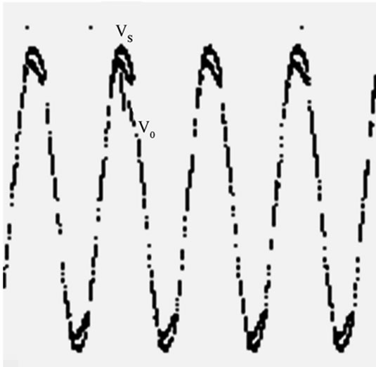
For proving above idea, an experimental circuit composed of a Source Follower pair (similar to Emitter Follower pair) where two MOSFETs are connected to the load in series so as to undertake low voltage stress(only several volts) both in positive half cycle and in negative half cycle. The electrical network is selected as the special AC supply and reference signal at the same time. Figure 1 shows the test circuit where the transformer controlled the amplitude of the AC supply voltage only a little higher than that of the gate voltage, which make the load voltage always track the gate voltage entirely with the same shape (amplitude, frequency and phase), however, the highest voltage drop on the device at the peak value transient only 3 volts. So the MOSFET pair circuit can get high efficiency, which can be calculated from Figure 2 as follows:
The loss of one active device in half a cycle is expressed by the equation.
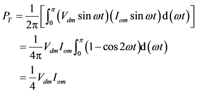 (1)
(1)
where
 : active device loss of linear unit in half a cycle.
 : peak value of voltage difference between the special ac supply voltage and the load voltage.
 : peak value of the load current.
The loss of one diode in half a cycle is expressed by the equation.
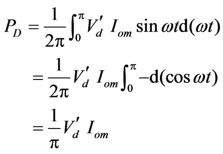 (2)
(2)
where
 : diode loss of linear unit in half a cycle.
 : the voltage dropping on the diode.

Figure 1. Simulated experimental circuit.
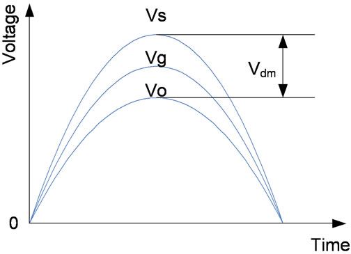
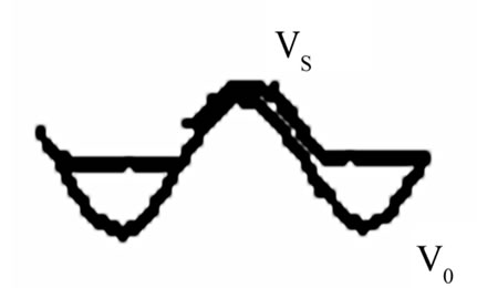
Figure 2. Supply voltage above load voltage (Vs, Vg, Vo are source voltage, gate voltage and load voltage respectively as shown in Figure 1).
Then, the efficiency of the MOSFETs linear unit can be approximately calculated as:
 (3)
(3)
where
 : power presented from the network.
 : special ac supply’s output voltage applying to the linear unit signed by RMS value.
For
 =110V,
  =3V,
=3V,  =0.7VThe rated operating efficiency of the MOSFETs linear unit can be calculated from (3) as:
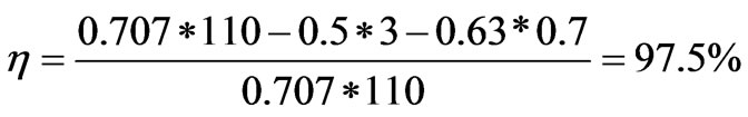 (4)
(4)
2.3. State Analyses
Indeed, the voltage controlled active device operates in a very special state while fed by the special AC supply, whose voltage is only a little higher than the gate voltage and the load voltage. Due to the low output resistance of Source Follower, the active device acts as a Source Follower getting constant output voltage regardless of the load shock, even changing the character from R to L, to C or to rectifier with a filter. It is evident that there is strong voltage feedback loop “ depends upon
 .” The current feedback function possesses the same direction as the voltage feedback function in the same loop. Also due to the high input resistance of Source Follower, any parameter change of the load is hard to interfere with the device gate voltage, so keeps the reference voltage of the gate strong robust. Furthermore, the feedback path is short enough with small time constant, leading to the fastest response in dynamic procedures among most of additional feedback loop. The above characteristics obey the regulation of Classical Electronics without doubt. However, in the present idea, it is required that the voltage drop on the active device as small as possible. If the experimental circuit is really modulated like this, the voltage controlled device will smoothly enter the adjustable resistance-region. Consequently the feedback procedure exhibits the active device to the conducting resistance. In this situation, the current adjustment corresponding to a fixed VDS still exists although the feedback action is not as strong as operating in the constant current-region. Hence the result is that in Source Follower configuration in step with a special AC supply, the active device operating in the critical region between the saturation region and the constant current region, an excellent synthetic performance as operating in conventional Source Follower with a DC supply will be expected, but the active device only undertakes the saturation voltage drop just liking operate under switch mode.
2.4. The Experimental Result of the Test Circuit
A series experiments are designed to demonstrate the performances emphasizing the robustness of a 100W/110V system in Figure 1. Because the gate voltage and the special AC supply voltage are practically feed from the same network with the same phase, which makes the load voltage firmly track the gate voltage with small voltage dropping on MOSFET devices, the waveforms on load can keep the original shape almost without change even under load shock procedures and meet the needs of different kinds of loads, including the nonlinear loads. These excellent performances are listed in Figures 3 (a-c), where (a) shows the tracking scheme and the possibility to realize high efficiency, (b), (c) show the robustness of the linear unit fed by a special AC supply.Then the question is that the above excellent performance got from the test circuit where the special AC supply directly took from the network via an adjustable transformer can not cover more practical applications. It only presents the belief results in theory and proves the possibility of implementing the new idea. Then the implementation is described as follow.
3. Implement of Switch Linear Hybrid
Taking a switch-filter unit replace the network AC supply in Figure 1, they construct a switch-linear unit hybrid circuit as shown in Figure 4, where the switch-filter unit produces the tooth-like ripple voltage feeding the serial MOSFETs, so the topology is named after SSLH (Series
 (a)
(a) (b)
(b) (c)
(c)
Figure 3. Fundamental experiments to prove initial idea. (a) Load voltage is coincide with the network with adjustable voltage; (b) Upper trace: 5 A/div., lower trace: 100 v/div., 100 ms/div. Rectifier-C-R load current & voltage (R = 100 Ω); (c) Upper trace: 0.1 A/div, lower trace: 100 v/div., 4 ms/div. Rectifier-R-L load current & voltage (R = 100 Ω).
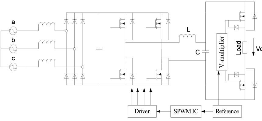
Figure 4. A kind of SSLH-topology.
Switch-Linear-Hybrid) converter while other topologies past paper described are named after PSLH (Parallel Switch-Linear-Hybrid) [1,3-6], because of the active devices connected in parallel with the supply and the load. Then the switch-filter unit produce tooth-like ripple voltage and the load voltage tracks the gate reference voltage, getting similar waveforms as in the previous simulation experiment.
It is obviously that as long as the voltage peak to peak value of the tooth-like ripples of the switch-filter unit is limited as small as Vdm in the previous simulation experiment, a satisfactory implementation of SSLH can be expected. So the switch frequency and LC parameters should be designed to satisfy Vdm. Since the tooth-like ripples will entirely drop on the active devices of linear unit, no longer appears on the load, the former stage of the switch-filter unit need not adopt too high switching frequency and too large LC values for good THD liking in the conventional switch-filter supplies. Thus the loss will be reduced in active and reactive devices of switchfilter unit at the same time. Furthermore, the efficiency of the linear unit in SSLH should be higher than that in Figure 1, because the peak to peak value is the same, the power supply in Figure 4 is the tooth-like ripple supply while in Figure 1 is the specify AC supply, so the loss on the power devices in the present linear unit is about half of that in the previous linear unit. So, it can be thought that SLH gets almost the same high efficiency as the conventional switch-filter converter with the same size.
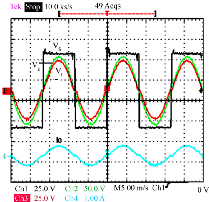
Using “Smart Wave Amplifier” to feed a MOSFET Emitter Followers as Switch-Filter unit, structuring the SSLH in Figure 4. A serie of idealized Tracking results can be obtained (See Figures 5 (a-d)). They prove obviously
 (a)
(a)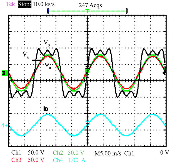 (b)
(b)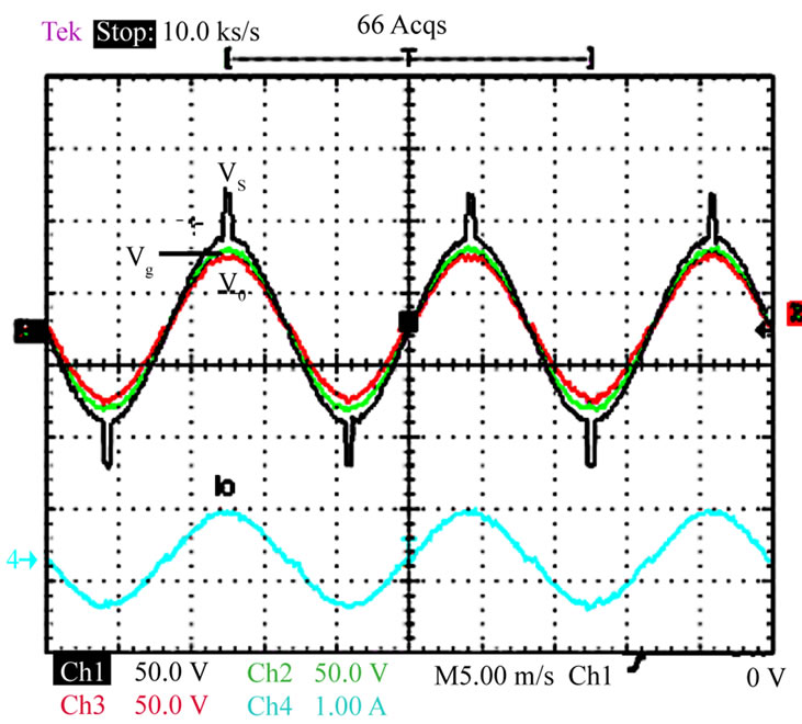 (c)
(c) (d)
(d)
Figure 5. Waveforms to show Gate-Tracked scheme of SSL. (a) Source waveform is rectangular; (b) Source waveform is the fundamental sine waveform superposed by 5 order’s harmonics; (c) Source waveform is the sine wave superposed by a spike; (d) Source waveform is step waveforms approaching to the fundamental sine waveform.
that as long as the gate voltage regulation is set up, the load voltage will track it steadily and dynamically, regardless of what kinds of sources to feed the Source Followers.
4. Extension and Application Prospect in Industry
According to the initial idea and the previous implementation, the SLH scheme can be simple expressed as in Figure 6 Various kinds of SSLH and PSLH can be extended from it and apply to industry. The switch-filter unit only operates as a power supply of the linear unit, feeding tooth-like waveform voltages to it. The linear unit operates as a voltage follower. The reference unit provides the switch-filter unit and the linear unit with the same required waveform reference signal. In this special condition, the Vs voltage value of the tooth-like ripples is controlled as small as a saturation voltage drop of active devices. And the active devices operate in a very strange state, near critical saturation, but still in linear range. So it gets both high efficiency and good load waveforms tracking the input voltage of the follower (proportional to the same reference signal controlling the switch unit).
While the reference is a standard sinusoidal reference of fixed frequency with high accuracy and stability, the high performance supply can be obtained. For instance a medical UPS often connects resistive light, thyristor-motor drive (nonlinear R-L load) and various intelligence apparatus at the same time. The SLH converter can meet the needs of complex loads and fast response. Some high efficient audio supplies adopted PSLH (Bi-BUCK circuit plus OCL circuit) has improved the audio products’ quality since 80’s of last century [7-8]. While the reference is adjustable frequency and amplitude waveform, the variable frequency supply or motor drive system will acquire better performance than PWM system under the same control strategy. Especially when they are operating at ultra-low frequencies, which is particularly beneficial to
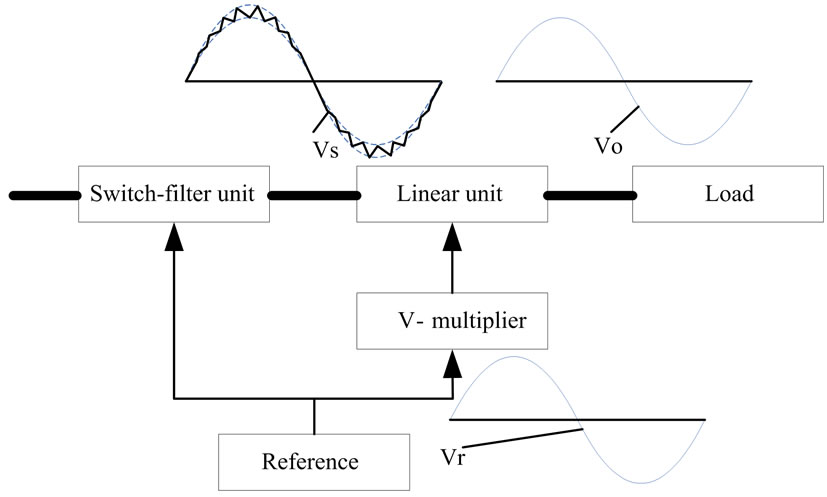
Figure 6. Unified structure block of SLH.
servo drive systems. While the reference is a smart waveform generator controlled by DSP, SLH can be used to design arbitrary waveform power amplifier with strong robustness, of course including DC supply.
Back to the simulated experiment circuit, it also can be applied directly to industry. For instance the constant voltage supplies only adjust the output voltage dynamically, but are hard to prevent the influence from the electrical network. While a lot of computers operate in a building, the voltage waveform of the building bus will be of distortion seriously. If the building network is not installed APF, connect a SLH converter with a standard sinusoidal reference in step with the network voltage to the original constant voltage supplies can solve it. Some equipments and apparatus feeding by the improved supplies can operate in good conditions. The improved constant voltage supplies can be developed into a new product series named after Wave-modified constant voltage supply.
5. Experimental Results
Typical comparison waveforms between conventional PWM-filter converters and SLH converters are list in Figures 7(a-m), where (b, c, d, e) show that the abilities of SLH converter suitable for nonlinear loads are much better than that of PWM-filter converter, and (fg) show that SLH-Inverter can feed the motor with sinusoidal voltage and current at ultra-low frequency regardless of the variation of motor parameters, while the SPWM-Invert can not if only a simple control strategy is adopted. It is obviously that the voltage and current waveforms of the latter are distorted seriously. The current spectrum in Figures 7(k, l, m) show SLH doesn’t produce 5, 7 order’s harmonic components, then reducing torque and speed ripples naturally while SPWM mode produces very high 5 order’s harmonic component.
 (a)
(a)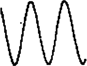 (b)
(b)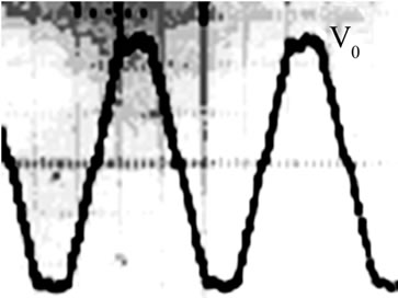 (c)
(c)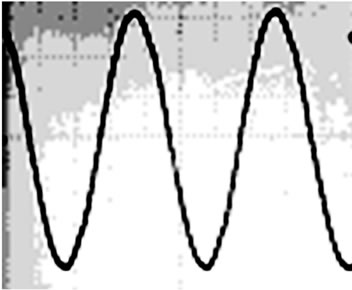 (d)
(d) (e)
(e)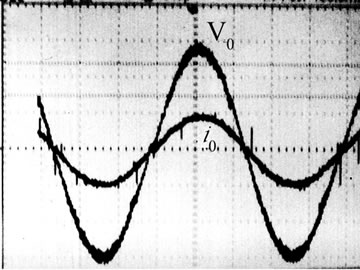 (f)
(f) (g)
(g)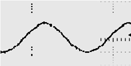 (h)
(h) (i)
(i)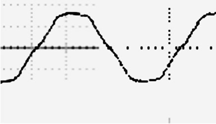 (j)
(j)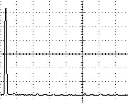 (k)
(k) (l)
(l) (m)
(m)
Figure 7. Typical comparison waveforms. (a) Vs above Vo of OCL-PSLH with 3 phase motor of 1.5 kW at 19 Hz; (b) Output voltage from a 1kVA of SSLH-UPS feeding a thyristor speed control drill of 600W, operating in full load or suddenly shut off; (c) Output voltage from a 1 kVA of SSLH-Inverter feeding a Rectifier-L-R load; (d) Output voltage of SSLH-UPS with 2 computers load, THD: 1.03%; (e) Output voltage of SPWM-UPS with 1 computer load (THD: 4.02% during with 2 computes); (f) Load phase voltage & current of SSLH with 0.6 kW motor, V/F control, 0.2 Hz; (g) Load phase voltage & current of SPWM -Inverter with 0.6 kW of motor, V/F control, at 0.2 Hz; (h) Load current of SSLH-Inverter with 0.6 kW motor, V/F control, 0.6 Hz; (i) Load current of SPWM-Inverter with 0.6 kW motor, V/F control, 0.6 Hz; (j) Load current of SPWM-LC-Inverter with 0.6 kW motor, V/F control, 0.6 Hz; (k) Load current spectrum of SSLH-Inverter with 0.6 kW of motor, V/F control, 0.6 Hz; (l) Load current spectrum of SPWM-Inverter with 0.6 kW of motor, V/F control, 0.6 Hz; (m) Load current spectrum of SPWM-LC-Inverter with 0.6kW of motor, V/F control, 0.6 Hz.
6. Conclusion
To meet the needs of integrated optimal performances, a Switch-Linear-Hybrid (SLH) power conversion is presented, which is made up of a switch-filter unit and a linear unit with Source Followers or Emitter Followers. The former feeds the latter as a power supply while the latter operates as a high efficient amplifier with good fidelity and strong robustness due to the low output resistance. Some conventional switch mode converter could make advance by means of SLH, developing various kinds of new topologies, such as SSLH and PSLH, keeping original merits, acquiring good waveform, high efficiency and strong robustness. SLH converter has a prospect future.
7. Acknowledgment
The authors gratefully acknowledge the contributions of Peng Jiang, Haibin Xu for past implementation of SLH in different topologies and the other’s continuous work.
REFERENCES
- Q. Z. Zhou and L. S. Ge, “Switch-Linearity Hybrid Power Conversion (SLH) with Low Output Resistance,” Proceedings of the 4th International Power Electronics and Motion Control Conference, Xi’an, Vol. 1, 14-16 August 2004, pp. 96-98.
- A. Barrado, R. Vázquez, E. Olías, A. Lázaro and J. Pleite, “Theoretical Study and Implementation of a Fast Transient Response Hybrid Power Supply,” IEEE Transactions on Power Electronics, Vol. 19, No. 4, July 2004, pp. 1003-1009. doi:10.1109/TPEL.2004.830034
- Q. Z. Zhou, et al., “Comparing Tracking Amplifying,” Frequency Changer, China Patent, No. 87106881.8.
- Q. Z. Zhou, Z. G. Chen and P. Jiang, et al., “A Novel High Performance Frequency Changer with Sine Waves Based on Voltage Comparing-Tracking-Amplifying Scheme,” Proceedings of the 4th European Conference on Power Electronics and Application, Florence, Vol. 4, No. 1, September 1991, pp. 324-329.
- Q. Z. Zhou, H. B. Xu and D. S. Wu, “Tracking-Type Active Power Filter,” China Patent, No. ZL00112420. X, 2003.
- Q. Z. Zhou, H. D. Zhang and K. Zhuang, “A Single-Three Phase Inverter Adopting SLH Scheme,” Journal of University of Electronics Science & Technology of China, Vol. 32, No. 6, 2003, pp. 655-660.
- Kashiwagis, “A High Efficiency Audio Power Amplifier Using a Self-Oscillating Switching Regulator,” IEEE Transactions on Industry Applications, Vol. 21, No. 4, 1985, pp. 906-911. doi:10.1109/TIA.1985.349540
- Q. Z. Zhou and X. D. Liu, “Switch-Linear Hybrid (SLH) Conversion Based on Source Follower,” IEEE Transactions on Power Electronics, Vol. 23, No. 5, 2008, pp. 2399-2410. doi:10.1109/TPEL.2008.2002051
NOTES
1Project Supported by National Nature Science Foundation of China (51067004).
Project Supported by Foundation of East China Jiaotong University (09DQ06).
.