Journal of Electromagnetic Analysis and Applications
Vol.4 No.4(2012), Article ID:18616,10 pages DOI:10.4236/jemaa.2012.44022
Extensions to the Finite Element Technique for the Magneto-Thermal Analysis of Aged Oil Cooled-Insulated Power Transformers
![]()
1Department of Electrical Engineering, Fayoum University, Fayoum, Egypt; 2Electric Power and Machines Department, Cairo University, Cairo, Egypt.
Email: J_shazly2001@yahoo.com, adlyamr@gmail.com
Received January 16th, 2012; revised February 19th, 2012; accepted March 5th, 2012
Keywords: Oil Insulated-Cooled Power Transformer; Finite Element Method; Electromagnetic Field Analysis; Thermal Analysis
ABSTRACT
It is well known that the hot spot temperature represents the most critical parameter identifying the power rating of a transformer. This paper investigates the effect of the degradation of core magnetic properties on temperature variation of aged oil-cooled transformers. Within this work, 2D accurate assessment of time average flux density distribution in an oil insulated-cooled 25 MVA transformer has been computed using finite-element analysis taking into account ageing and stress-induced non-uniform core permeability values. Knowing the core material specific loss and winding details, local core and winding losses are converted into heat. Based upon the ambient temperature outside the transformer tank and thermal heat transfer related factors, the detailed thermal modeling and analysis have then been carried out to determine temperature distribution everywhere. Analytical details and simulation results demonstrating effects of core magnetic properties degradation on hot spot temperatures of the transformer’s components are given in the paper.
1. Introduction
Considerable attention has been directed towards the thermal analysis of power transformers in recent years. Obviously, maximum temperature at which the insulation of the power transformer can operate and the method of heat dissipation through it and its surrounding should be determined during design stages. Moreover, accurate identification of the location and magnitude of a transformer hot spot temperature could also be very useful in transformer design stage and/or cooling strategies [1].
In previous work, some efforts have been carried out to assess transformer’s components maximum temperatures [2,3]. The theoretical thermal model developed was limited by the basic assumption of uniform distribution of heat generated per unit volume per unit time in both the iron core and the copper conductors. Within this assumption, winding insulation was not taken into account.
This study investigates the effect of the degradation of core magnetic properties on the temperature distribution as well as values of hot spot, top gas and tank temperatures of aged oil-cooled transformers. More specifically, effects of global and local core permeability variation resulting from ageing and/or maintenance-related introduced mechanical stresses are considered. Two-dimensional accurate assessment of time average flux density distribution has been computed using finite-element method to identify the core and winding losses which are converted into heat. Based upon the ambient temperature outside the transformer tank and thermal heat transfer related factors, detailed thermal modeling and analysis have been then carried out to determine temperature distribution everywhere. The thermal analysis included; heat conduction, free convection inside the oil tank, forced convection outside the tank, and radiation from tank surfaces.
Analytical details and simulation results demonstrating effects of core magnetic properties degradation on transformer’s temperatures are given in the following sections of the paper. It should be pointed out that, throughout the paper, numerical simulation of the electromagnetic field and the heat transfer analysis has been carried out with the aid of ANSYS finite element software package.
2. Mathematical Model
It is well known that losses occurring in the magnetic core, windings and parts of an operating transformer are converted into heat. An electromagnetic finite element method is proposed to evaluate those generated losses, which are used as the thermal analysis heat sources. Obviously, heat is transferred to the surrounding air via several stages due to a temperature difference at the boundaries of each stage. The first stage of heat transfer begins from the interior of the core or the windings and extends to their external surfaces by conduction. The second stage is the transfer of heat from the windings and the core to the oil by convection. The third stage is the transfer of heat from the oil to the inner tank walls by convection. The fourth stage is the transmission of heat energy through the thickness of the tank walls by conduction. In the last stage, heat is dissipated from the external tank walls to the surrounding air by convection and radiation.
The theoretical analysis presented in this paper is based on the following assumptions:
1) The transformer structure can be considered as a plane-parallel geometry. Therefore, with a reasonable acceptable accuracy, the three-dimensional (3-D) problem is reduced to a two-dimensional (2-D) one with x and y as space variables, with elements layout for finite element formulation, as shown in Figure 1.
2) The phase currents are sinusoidal and balanced. Consequently, all field quantities will by sinusoidal with time.
3) The base of the tank is assumed to be insulated and measured values of ambient temperature are always considered.
4) The insulation between the low voltage winding and high voltage winding is taken into consideration.
5) All electrical and thermal material properties have been considered as given in [4] and [5]. Thermo-physical properties of the materials are supposed to be function of temperature.
The associated steady state heat conduction equation for the two-dimensional model can be described—as given in [6] and [7]—by:
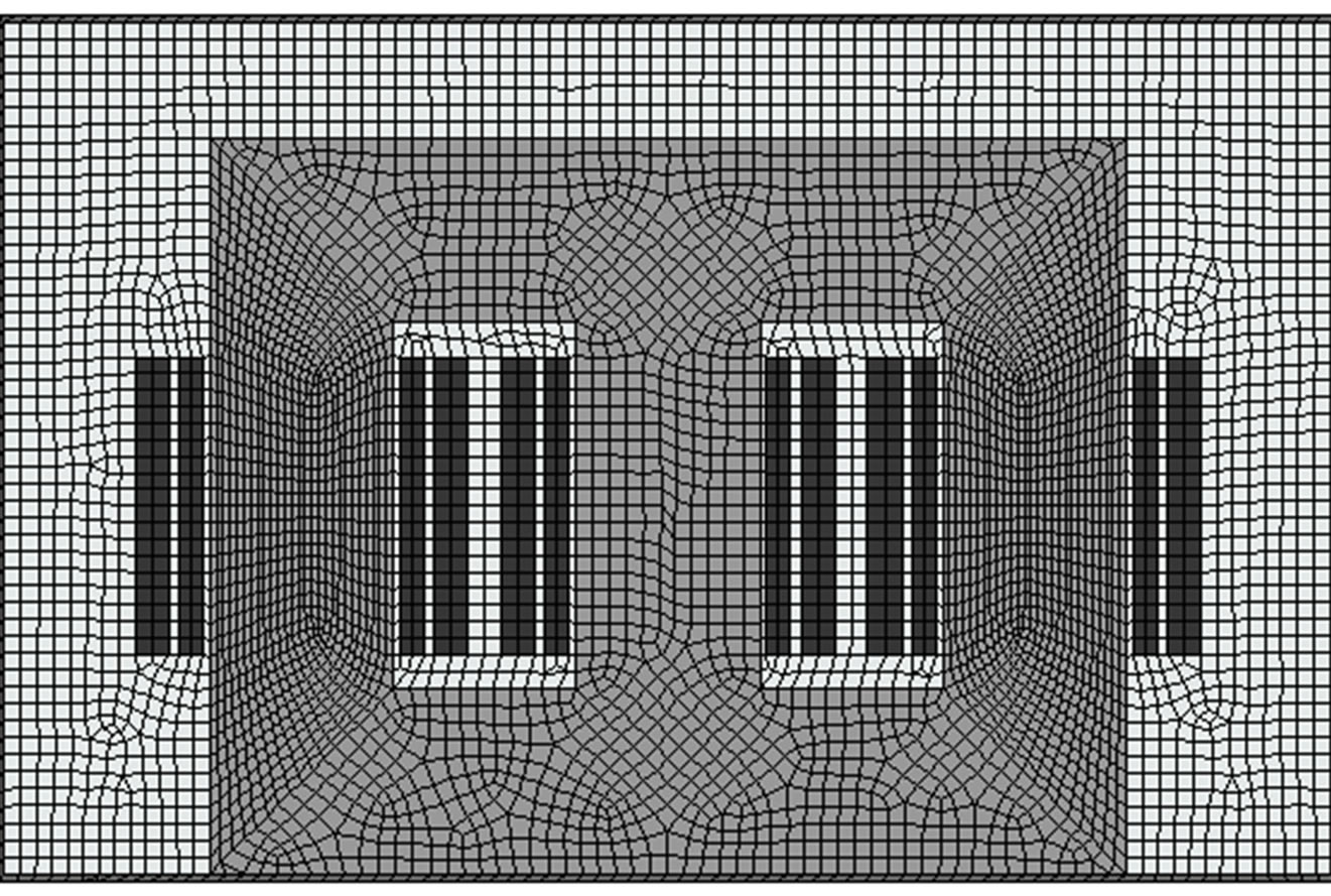
Figure 1. Schematic of transformer with elements layout for finite element formulation.
 (1)
(1)
where T is temperature in (˚C), x and y are spatial variables in (m), K is the thermal conductivity in (W/m·˚C) and  is the heat transfer rate in (W/m3).
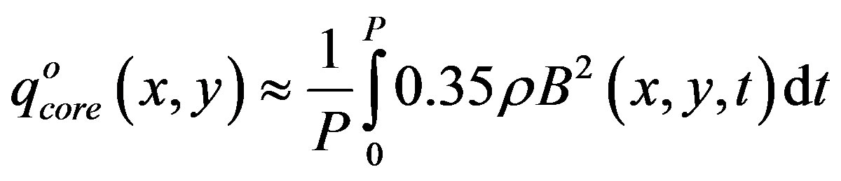
Within this steady state analysis, and due to the difference between electrical and thermal systems response time, steady state heat generated in transformer parts due to power dissipation is averaged over the power mains cycle period P. Taking this fact into consideration and referring to typical loss specifications for cold-rolled silicon steel (Si-Fe) sheets data (which may be approximated by the expression ), the heat generated per unit volume per unit time at any point (x, y) in the iron core may be computed from [8]:
 (2)
(2)
where B is the magnetic flux density (in Tesla) and t is the time instant, while  is the density of iron core (kg/m3).
Likewise, the heat generated per unit volume per unit time at any point  in the coils may be computed from:
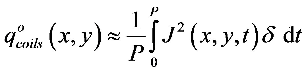 (3)
(3)
where J is the current density in (A/m2), and  is the resistivity in (Ω·m).
Within the transformer thermal model, there are convective heat transfer between the winding surfaces, the core surface and the oil flowing over them, then from the oil to the inner surface of the tank, and finally from the external tank walls to the surrounding air. The mathematical formulation of this convection boundary condition is obtained by considering an energy balance at the surface stated as:
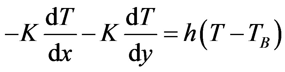 (4)
(4)
where,  is the adjacent bulk temperature while h is the convective heat transfer coefficient in (W/m2·C) which could be determined by classical Nusselt number Nu correlations as [6]:
 (5)
(5)
The outer surface of the transformer components was considered similar to a vertical or horizontal plate with uniform heat flux. For vertical plates the characteristic dimension L = height in (m); while for horizontal plates the characteristic dimension L = length in (m).
There are several convective heat transfer coefficients that must be evaluated to determine the temperatures of the transformer. It should be pointed out that, the convective heat transfer coefficients are based on the assumption that only free convection is suggested under transformer loading conditions as instructed by the manufacturer. In the presence of external fans, forced convection due to air circulation outside the transformer tank may also be taken into account. Average Nusselt numbers Nu for forced and free convection on horizontal and vertical plates are given in [2] and [6].
Radiation effects generally appear in the heat transfer analysis only through the boundary conditions. In this model, an open type enclosure surface radiates heat between the external surfaces of the tank and the surrounding air with predetermined ambient temperature. The mathematical formulation of this radiation boundary condition is obtained—as discussed in [6,7], and [9]— by considering the following energy balance expression:
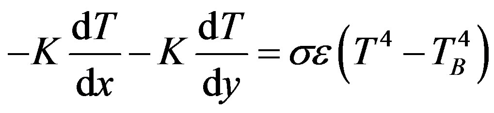 (6)
(6)
where,  is Stefan-Boltzmann constant,
  w/m2·K4. Note that ε is the infrared emissivity = 0.95 in this model [6].
3. Testing and Numerical Results
In order to test the suggested methodology, detailed configuration of a 25 MVA, 66 KV/11 KV (ONAF), oil cooled-insulated power transformer was considered [10]. For this transformer the core length, core height, window width and window height were about 2.5 m, 2.1 m, 0.5 m and 1.1 m, respectively. Thickness and height of each winding were about 0.l m and 1.0 m, respectively, and inter-spacing between tank walls and active transformer parts was about 0.3 m. Low voltage and high voltage windings were the inner and outer ones, respectively.
3.1. No Ageing Case
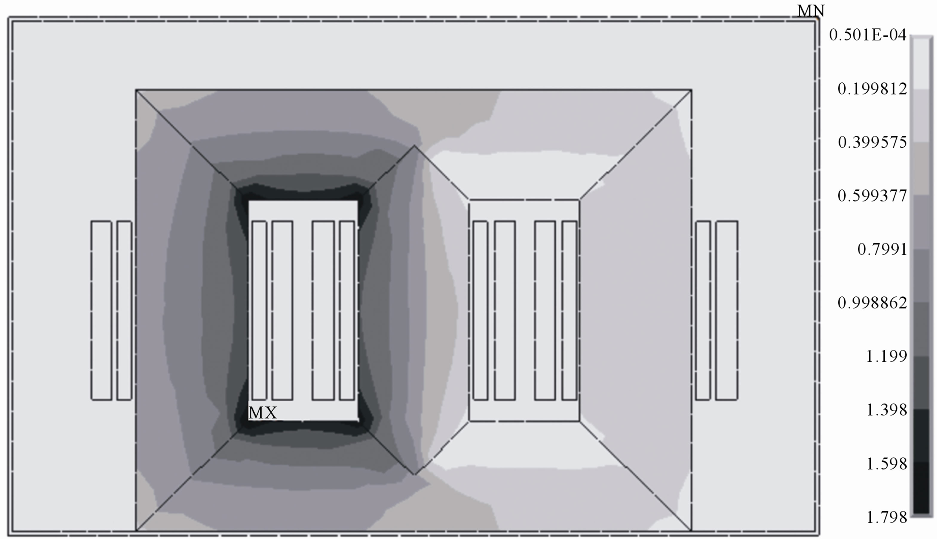
Normal performance and thermal profile was first assessed as a reference to ageing situations. For normal operation, the flux density distribution  and current density distribution
  in every transformer location were first computed at different time instants over a complete power mains cycle. Those locations include winding parts, core and tank walls. Such computation was carried out using 2D finite element analysis assuming cold rolled Si-Fe sheets having axial and transverse working relative permeability values of 3500 and 350, respectively. Sample flux density computation results for instants corresponding to peak left-limb current (a), peak middle-limb current (b), and peak rightlimb current values (c), are given in Figure 2. The predicted flux density values using the method proposed in this paper are compared with industrial results referred to in [10] and reflect a satisfactory quantitative agreement.
Thermal analysis in accordance with (1)-(6) was then carried out using finite-element analysis and for  = 7800 kg/m3, winding
  = 1.7e–8 Ω·m and tank
  = 1e–5 Ω·m. Overall thermal analysis profile and temperature values at a horizontal plane bisecting the core are shown in Figures 3 and 4.
 (a)
(a) (b)
(b)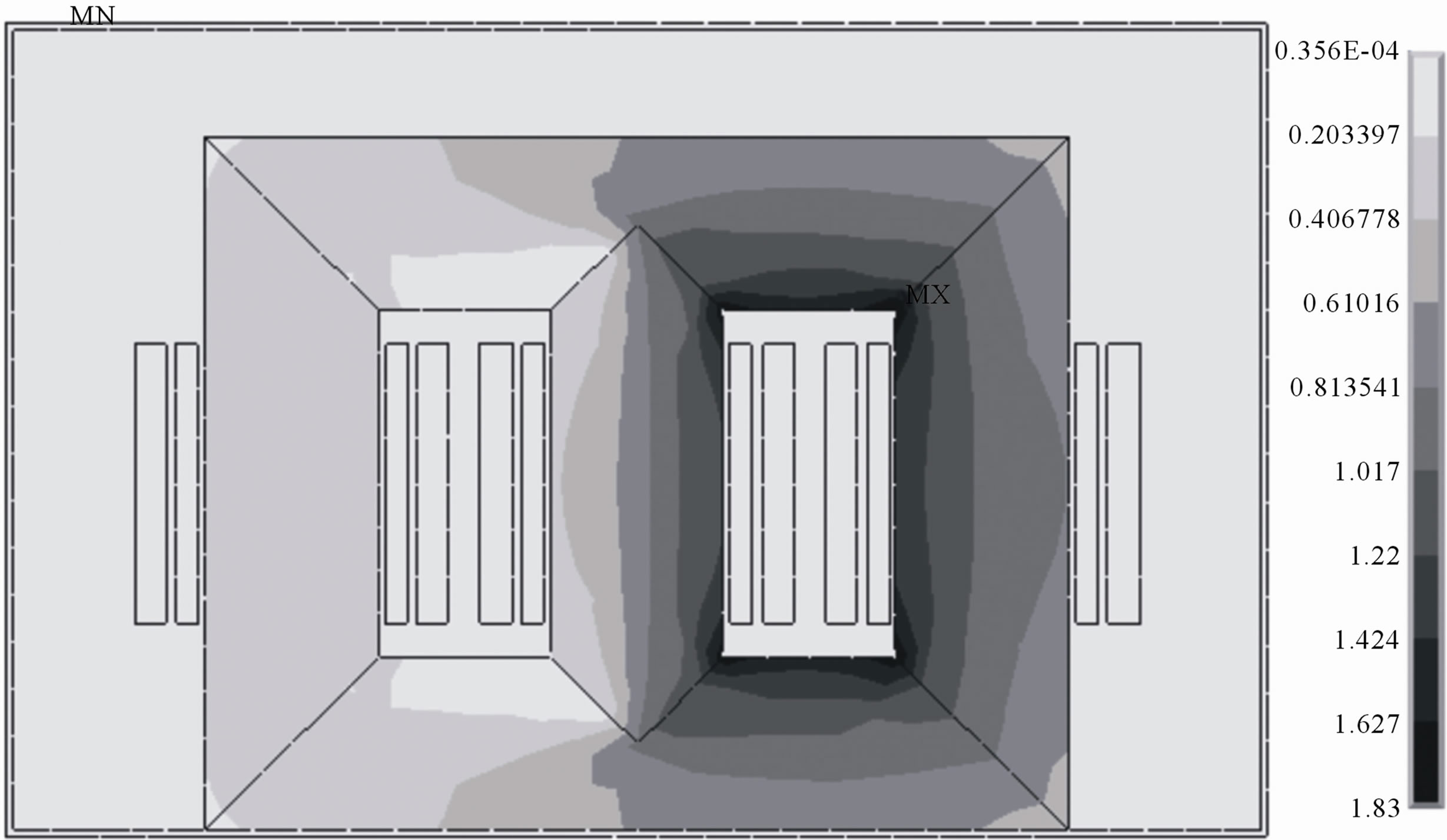 (c)
(c)
Figure 2. Sample flux density computation results for instants corresponding to peak left-limb current (a), peak middle-limb current (b) and peak right-limb current values (c) for the transformer when having normal magnetic properties.
Figure 3 shows the contour plot for a nodal temperature distribution of the oil cooled-insulated power transformer at full load (25 MVA). Obviously, hot spot temperature is expected to be located somewhere on the horizontal line through the center of the T-joint of the core [11]. For the depicted locations of the aforementioned line, Figure 4 suggests that the values of the hot spot of iron core temperature, winding temperature, top gas temperature, and the tank temperature are 96˚C, 92˚C, 91˚C and 49˚C, respectively.
It is clear from these two figures that the thermal profile is symmetric with respect to the middle axis of the whole transformer because the transformer’s sides are exposed to similar conditions. It is also clear that hot spot
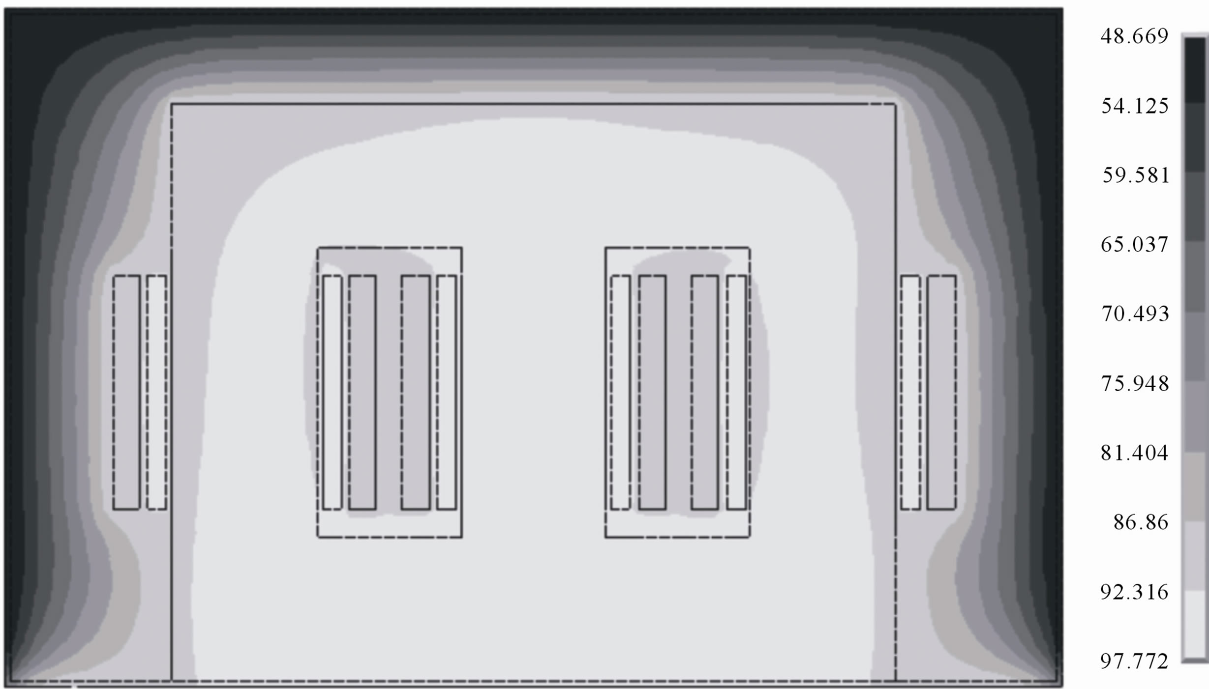
Figure 3. Overall thermal analysis profile for the transformer when having normal magnetic properties.
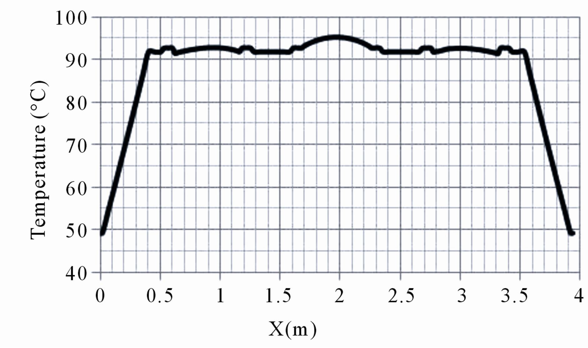
Figure 4. Temperature values at a horizontal plane bisecting the core for the transformer when having normal magnetic properties.
winding temperature is expected to be at the center of the low voltage windings in general. Estimated value of the hot spot winding temperature was found to be around 92˚C, which is in agreement with industrially reported temperatures for this transformer.
3.2. Case of Aged Right Limb
Ageing of transformers mainly affects the oil insulation properties. Degradation in oil properties eventually results in short circuiting a winding. Whether the limb bearing this winding is exposed to high instantaneous electromagnetic forces during the short circuit event or as a result of mechanical stresses imposed due to improper re-winding procedures, probability to end up with irreversible local magnetic properties degradation becomes quite high [12]. Moreover, ageing also affects thermal properties of oil. Consequently, long periods of high temperatures exposure of Cold-rolled Si-Fe sheets also could lead to a degradation of magnetic properties as well. In order to demonstrate the thermal consequences of local magnetic properties degradation as a result of the aforementioned ageing scenarios, magnetic and thermal analysis for the transformer under consideration were carried out. All properties were assumed similar to the normal case with the exception of the right limb where axial and transverse working relative permeability values of 2000 and 200, respectively.
For this particular aged case, sample flux density computation results for instants corresponding to peak leftlimb current (a), peak middle-limb current (b), and peak right-limb current values (c) are given in Figure 5. Moreover, overall thermal analysis profile and temperature values at a horizontal plane bisecting the core are shown in Figures 6 and 7.
Unlike for the results shown in Figure 3, the thermal profile is not symmetric anymore with respect to the middle axis of the whole transformer. The same is true for the hot spot temperature. More specifically, temperature values of windings of wound around the limb having inferior magnetic properties are higher (about 95˚C instead of 92˚C). This difference will increase as the magnetic properties further degrade. Moreover, this will result in higher winding resistance that could result in more heat loss and, consequently, further increase in local temperature rise. It should be stated that in accordance with the IEC code, excessive hot spot temperature rise will directly affect the transformer overall life time [13].
3.3. Case of Aged Yoke
If the yokes are exposed to high instantaneous electromagnetic forces or as a result of mechanical stresses, probability to end up with irreversible local magnetic properties degradation becomes quite high. Moreoverageing also affects thermal properties of oil. Consequently, long periods of high temperatures exposure of cold-rolled Si-Fe sheets also could lead to a degradation of magnetic properties as well. In order to demonstrate the thermal consequences of local magnetic properties degradation as a result of the aforementioned ageing scenarios, magnetic and thermal analysis for the transformer under consideration were carried out. All properties
 (a)
(a) (b)
(b)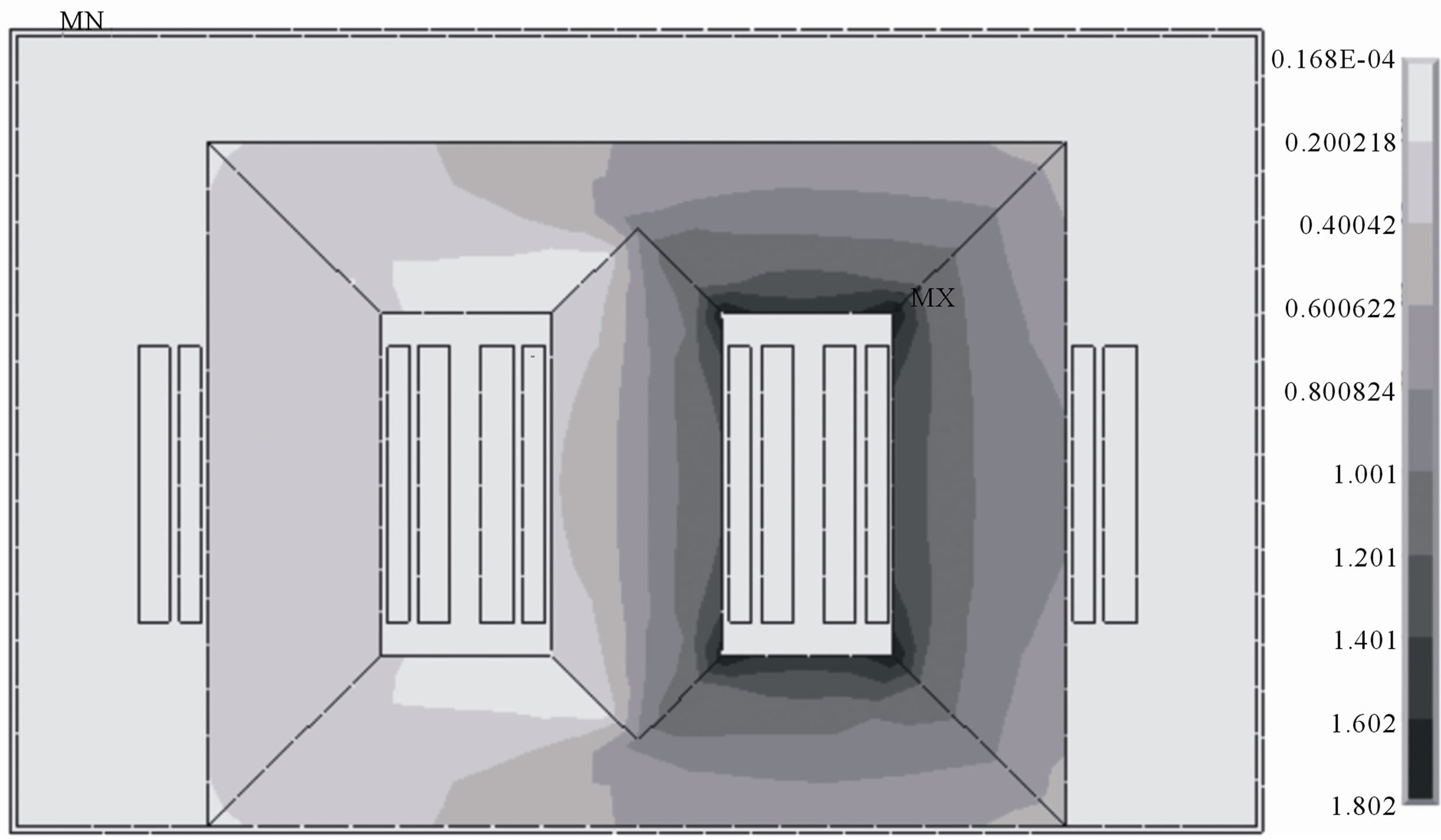 (c)
(c)
Figure 5. Sample flux density computation results for instants corresponding to peak left-limb current (a), peak middle-limb current (b) and peak right-limb current values (c) for the transformer when having degraded right limb magnetic properties.
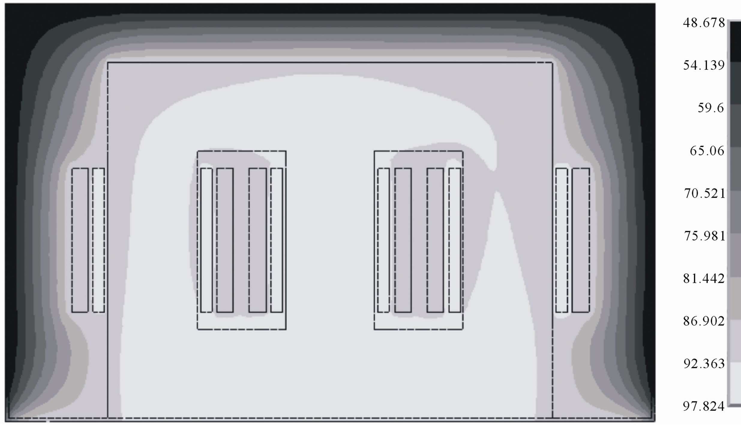
Figure 6. Overall thermal analysis profile for the transformer when having degraded right limb magnetic properties.
were assumed similar to the normal case with the exception of the yokes where axial and transverse working relative permeability values of 2000 and 200, respectively.
For this particular aged case, sample flux density computation results for instants corresponding to peak left-limb current (a), peak middle-limb current (b), and peak right-limb current values (c) are given in Figure 8. Overall thermal analysis profile and temperature values at a horizontal plane bisecting the core are shown in Figures 9 and 10. It is observed from these two figures that the thermal profile is symmetric with respect to the middle axis of the whole transformer. More specifically,
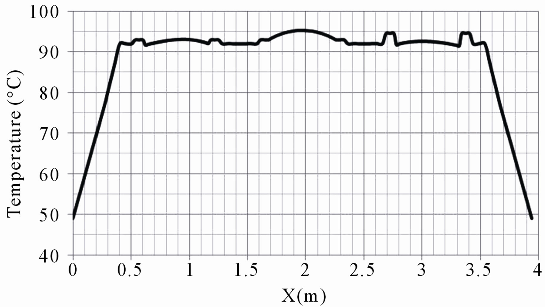
Figure 7. Temperature values at a horizontal plane bisecting the core for the transformer when having degraded right limb magnetic properties.
temperature values of windings of wound around the limb having inferior magnetic properties are higher (about 97˚C instead of 92˚C). This difference will increase as the magnetic properties further degrade that could result in more heat loss and, consequently, further increase in local temperature rise.
4. Conclusion
This paper has presented a combined magneto-thermal analysis for calculating the thermal fields at any specified location within the oil cooled-insulated power transformer, using finite element technique. This analysis is more precise than any other previously developed model
 (a)
(a) (b)
(b) (c)
(c)
Figure 8. Sample flux density computation results for instants corresponding to peak left-limb current (a), peak middle-limb current (b) and peak right-limb current values (c) for the transformer when having degraded yoke magnetic properties.
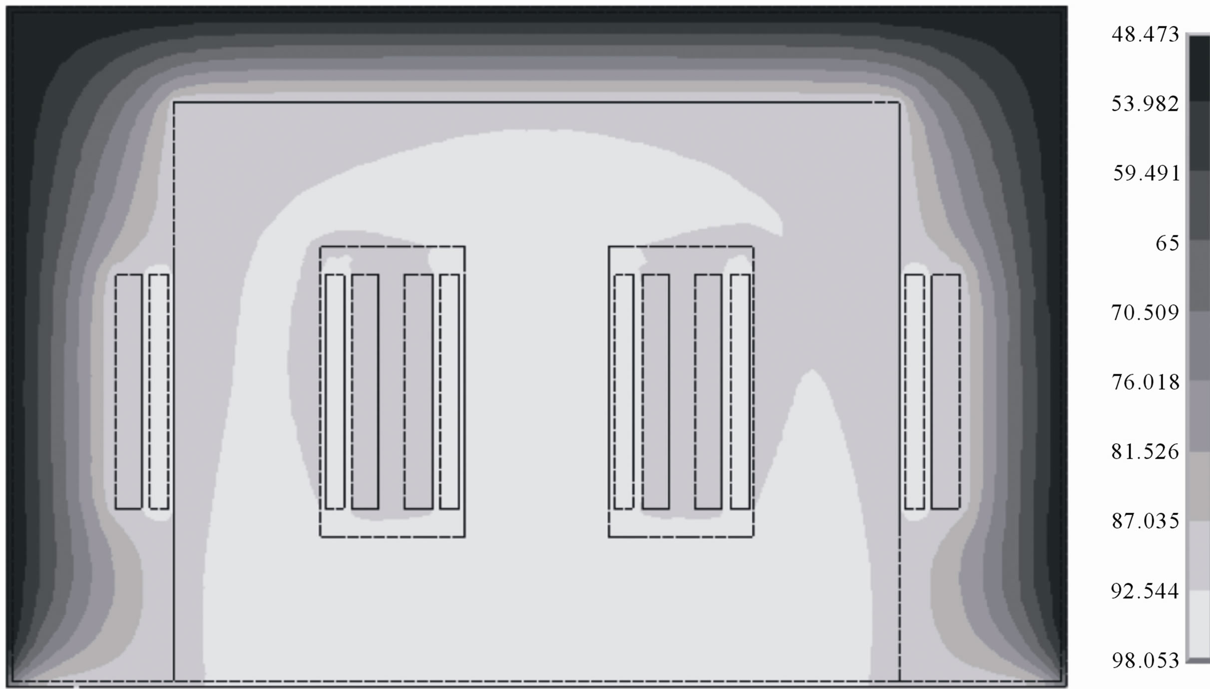
Figure 9. Overall thermal analysis profile for the transformer when having degraded yoke magnetic properties.
because it considers effects of global and local core permeability variation resulting from ageing and/or maintenance-related introduced mechanical stresses are considered, and the contributions of the convective and radiative heat transfers. The thermal model developed here can predict the hot spot location, with a reasonable degree of accuracy during the design stage. This will in turn allow for better transformer performance when it is put in service. It can be concluded from the presented analysis and simulation results that degraded local magnetic properties would have an impact on thermal profile of a power transformer and, consequently, increasing its hot spot temperature. The proposed analysis approach may be extended to cover the tank outside vicinity in order to
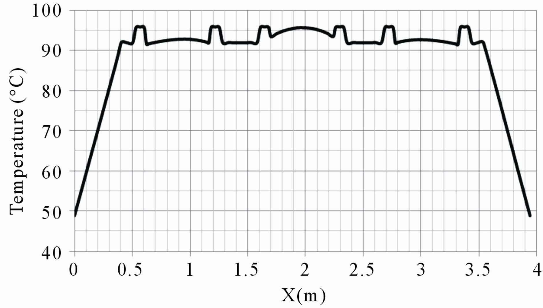
Figure 10. Temperature values at a horizontal plane bisecting the core for the transformer when having degraded yoke magnetic properties.
thermally monitor any magnetic property degradation signs.
REFERENCES
- L. W. Pierce, “Hottest Spot Temperatures in Ventilated dry Type Transformers,” IEEE Transactions on Power Delivery, Vol. 9, No. 1, 1994, pp. 257-264. doi:10.1109/61.277697
- E. M. Eteiba, M. M. A. Aziz and J. H. Shazly, “Heat Conduction Problems in SF6 Gas Cooled-Insulated Power Transformers Solved by the Finite-Element Method,” IEEE Transactions on Power Delivery, Vol. 23, No. 3, 2008, pp. 1457-1463. doi:10.1109/TPWRD.2008.915793
- E. M. Eteiba, M. M. A. Aziz and J. H. Shazly, “Sensitivity of Steady-State Temperatures of SF6 Gas-Cooled-Insulated Power Transformers to Selected Parameters,” IEEE Transactions on Power Delivery, Vol. 24, No. 3, 2009, pp. 1249-1256. doi:10.1109/TPWRD.2009.2021028
- B. S. Guru and H. R. Hızıroğlu, “Electromagnetic Field Theory Fundamentals,” 2nd Edition, Cambridge University Press, Cambridge, 2004.
- G. D. Raithby and K. G. T. Hollands, “Handbook of Heat Transfer,” 3rd Edition, McGraw-Hill Book Company, New York, 1998.
- M. N. Ozisik, “Heat Transfer a Basic Approach,” McGraw-Hill Book Company, New York, 1985.
- S. J. Salon, “Finite Element Analysis of Electrical Machines,” Kluwer Academic Publishers, Boston, 1995. doi:10.1007/978-1-4615-2349-9
- C. C. Hwang, “Numerical Computation of Eddy Currents Induced in Structure Steel Due to Three-Phase Current,” Electric Power Systems Research, Vol. 43, No. 2, 1997, pp. 143-148. doi:10.1016/S0378-7796(97)01177-2
- R. Siegel and J. R. Howell, “Thermal Radiation Heat Transfer,” McGraw-Hill Book Company, New York, 1990.
- A. Saleh, A. Adly, T. Fawzi, A. Omar and S. El-Debeiky, “Estimation and Minimization Techniques of Eddy Current Losses in Transformer Windings,” Proceedings of the CIGRE Conference, Paper No. 12-105, Paris, 2002.
- E. G. teNyenhuis, R. S. Girgis, G. F. Mechler and G. Zhou, “Calculation of Core Hot-Spot Temperature in Power and Distribution Transformers,” IEEE Transactions on Power Delivery, Vol. 17, No. 7, 2002, pp. 991- 995. doi:10.1109/TPWRD.2002.803703
- A. A. Adly and S. K. Abd-El-Hafiz, “Utilizing Particle Swarm Optimization in the Field Computation of Nonlinear Media Subject to Mechanical Stress,” Journal of Applied Physics, Vol. 105, 2009, p. 07D507.
- IEC 354, “Loading Guide for Oil-Immersed Power Transformers,” 2nd Edition, 1991.
Abbreviations and Acronyms
B The magnetic flux density in Tesla
h Convective heat transfer coefficient, W/m2·C
J The current density, A/m2
K Thermal conductivity, W/m·C
L Length, m
Nu Nusselt number, dimensionless
qo The rate of heat per unit volume per unit time, W/m3
t Time, sec
T Temperature, C
TB Bulk temperature of the adjacent fluid, C
X X direction
Y Y direction
ε Infrared emissivity, dimensionless
σ Stephen-Boltzman constant, 5.67 × 10⁻⁸ W/m2·K4
ρ Density, kg/m3
δ The resistivity, Ω·m