Journal of Electromagnetic Analysis and Applications
Vol. 2 No. 11 (2010) , Article ID: 3297 , 7 pages DOI:10.4236/jemaa.2010.211083
New Interfacial Shear-Horizontal Waves in Piezoelectric Cubic Crystals
![]()
International Institute of Zakharenko Waves, Krasnoyarsk, Russia.
E-mail: aazaaz@inbox.ru
Received September 15th, 2010; revised October 20th, 2010; accepted October 23rd, 2010.
Keywords: New Shear-Horizontal Interfacial Wave, Strong Piezoelectric Effect, Piezoelectric Cubic Crystals, Solutions for “Latent” Waves
ABSTRACT
This theoretical study reports results on acoustic wave propagation along the interface of two half-spaces representing cubic crystals of both piezoelectric classes `43m and 23 with strong piezoelectric effect. In similar configurations, the interfacial Maerfeld-Tournois waves can propagate along the interface of two transversely-isotropic materials of class 6 mm, in which the shear-horizontal surface acoustic waves (SH-SAWs) called the Bleustein-Gulyaev (BG) waves can also exist. Cubic piezoelectrics cannot support existence of the surface BG-waves, according to the recent report by Gulyaev and Hickernell. Hence, new interfacial SH-waves are studied in this paper concerning unique direction [101] of wave propagation in cubic crystals using different electrical boundary conditions (EBCs) of both metallized and non-metallized interfaces. The new interfacial SH-waves can always propagate along the interface of two identical piezoelectric crystals with opposite polarization. In this case, the calculated velocities for both EBCs coincide with the velocity of the ultrasonic surface Zakharenko wave (USZW) propagating in direction [101] on the metallized surface of a cubic piezoelectrics. It was also found that the new interfacial SH-waves can exist when wave propagation is along the interface of two dissimilar half-spaces, for instance, the piezoelectric cubic crystals Bi12SiO20 and Bi12GeO20. Several calculations are also carried out as examples. PACS: 51.40.+p, 62.65.+k, 68.35.Gy, 68.35.Iv, 68.60.Bs, 74.25.Ld.
1. Introduction
The theoretical investigations carried out in 1971 by Maerfeld and Tournois [1] introduced an acoustic shear-horizontal (SH) wave guided by the common interface of two semi-infinite media, if at least one of the media is a piezoelectric material. Maerfeld and Tournois have stated the existence conditions for such waves called the interfacial Maerfeld-Tournois (MT) waves, which can also propagate along the interface of two identical transversely-isotropic crystals of class 6 mm, when the C-axes of the crystals are in opposite directions, satisfying the perpendicularity condition of the wave propagation direction to an even-order symmetry axis. This is similar to the other shear-horizontal surface acoustic waves (SH-SAWs) simultaneously discovered by Bleustein [2] and by Gulyaev [3] in the late 1960s, which possess a hybridization between the mechanical displacement U2 and electrical potential φ = U4. These two types of SH-waves, namely the interfacial MT-waves and surface Bleustein-Gulyaev (BG) waves, can only propagate along surfaces of suitable crystal cuts of transversely-isotropic crystals of the hexagonal and tetragonal classes 6 mm and 4 mm. It is thought that these surface SH-waves have deeper penetration length and lower energy loss than do surface Rayleigh waves [4]. Therefore, they can be easily excited and detected.
The recent work [5] by Gulyaev and Hickernell noted impossibility of SH-SAW existence in piezoelectric cubic crystals. In addition, Ref. [6] discussed that SH-SAWs on electrically open or shorted surfaces of piezoelectric crystals of classes 622 and 422 cannot exist if the propagation direction is perpendicular to six or four-fold axes. However, the surface BG-waves can be found as soon as the transversely-isotropic symmetry decreases from class 622 to 6 or from class 422 to 4. It is noted that both the surface BG-wave and interfacial electro-acoustic MTwave may be caused by interfacial crack propagation between two dissimilar piezoelectric crystals.
The purpose of this report is to introduce theoretical investigations of new interfacial SH-waves in piezoelectric cubic crystals with the strong piezoelectric effect. The Chalcogenide family crystals (Tl3VS4 and Tl3TaSe4 [7]) belonging to the cubic class `43m and possessing both zero temperature coefficients and strong piezoelectric coupling, are examined. In spite of their very large potential interest, especially for moderate frequency and large bandwidth, such ternary thallium Chalcogenides Tl3TaSe4 are not commercially available, probably due to their mechanical softness and fabrication difficulties. However, the piezoelectric ceramics of the point group symmetry 23 (Bi12SiO20 and Bi12GeO20 [8] and Bi12TiO20 [9]) can be used in piezoelectronics. Recently, new SH-SAWs [10] called the ultrasonic surface Zakharenko waves (USZWs) were discovered in such cubic piezoelectrics with the strong piezoelectric effect. Note that some piezoelectrics display colossal enhancement of piezoelectricity [11]. It is noted that over several hundred piezoelectric materials, particularly piezoelectric ceramics or composites, are known, for example see Ref. [12], having their intrinsic electromechanical coupling behaviors. They are widely used today for different applications such as filters and sensors, as well as actuators and ultrasonic generators.
Concerning fabrication of a structure consisting of two dissimilar crystals, a process called wafer bonding is utilized in the semiconductor industry, allowing two different materials to be rigidly and permanently bonded along a plane interface, thus producing a composite bi-material [13]. It is noted that several hundred wafer bonding patents are annually deposited [14]. In addition, a similar second process called fusion bonding is used by the polymer industry to bring together two parts of different solid polymers, thus enabling the manufacture of a heterogeneous bi-material with specific properties [15,16]. In the first process, wafers of two different crystals are stuck together through Van der Waals forces, after their surface has been mirror-polished. In the second, however, a fusion process followed by a cooling and consolidating period takes place at the interface. It is obvious that it is important to be able to inspect the strength of the bonding, possibly through non-destructive ultrasonic evaluation. However, very few simple numerical investigations exist to compute the speed, etc., of interfacial waves when they exist.
2. Theory
Figure 1 introduces a rectangular coordinate system (x1, x2, x3) so that the x1Ox3 sagittal plane is perpendicular to the even-order symmetry axis of a piezoelectric cubic crystal and the x1-axis demonstrates wave propagation in
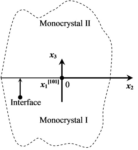
Figure 1. The rectangular coordinate system with the x2-axis directed along the interface of two half-spaces where the x1-axis is directed perpendicular to the figure plane.
direction [101]. It is necessary to write governing equations of linear piezoelasticity. Constitutive relations are written as follows:
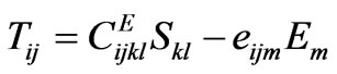 (1)
(1)
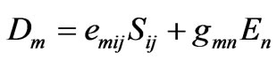 (2)
(2)
in which Tij and Sij are the stress and strain tensors, respectively; Dm and Em are components of the electrical displacement and electrical field (Em = – ∂φ/∂xm where φ is the electrical potential); the indices i, j, k, l , m, and n run from 1 to 3. According to the Voigt notation, Cijkl, eijm, and gmn can be written as 6 × 6, 3 × 6, and 3 × 3 matrices standing for the elasticity, piezoelectricity, and dielectricity tensors, respectively. It is assumed that studied materials are free of body forces and inertial effects as well as body electric charge. The equilibrium equations are as follows: ∂Tij/∂xj = 0 and ∂Di/∂xi = 0.
The equation of motion of an elastic medium is written as follows:
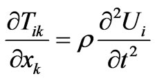 (3)
(3)
where ρ and Ui denote the mass density and mechanical displacement components; t is time. Using equations from (1) to (3), the coupled equations of motion for a piezoelectric medium are written in the following forms:
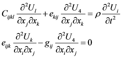 (4)
(4)
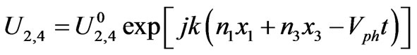
with U4 = φ. Solutions of the homogeneous partial differential Equation (4) of the second order are found in the following plane wave form:
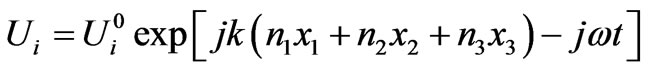
where the index i runs from 1 to 4; Ui0 is an initial amplitude. The imaginary unity is defined as j = (–1)1/2 and ω is the angular frequency. k is the wavenumber in the k-space with the following components {k1, k2, k3} = k{n1, n2, n3} and {n1, n2, n3} are the directional cosines. {x1, x2, x3} are the components of real space.
Leaving only equations for waves with polarization perpendicular to the sagittal plane and non-zero components of the material tensors, the coupled equations of motion in Equation (4) can then be written in the following convenient forms:
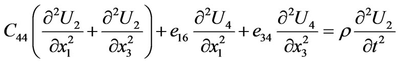
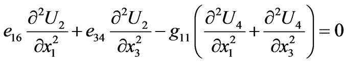 (5)
(5)
where the mechanical displacement component U2 is directed along the x2-axis shown in figure 1:
 (6)
(6)
In Equation (6), the phase velocity is defined as vph = w/k. Equation (5) describes wave propagation in direction [101] with e14 = e36 = 0 and the non-zero piezoelectric constants {e16, e34}. It is thought that such cuts of cubic crystals can be readily done. Note that all propagation directions perpendicular to direction [010] can exist giving C44 = C66 and g11 = g33 concerning piezoelectric cubic crystals.
Using Equations (5) and (6), the tensor form of equations of motion can be written with corresponding GL-components in the Green-Christoffel equations: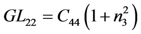 ,
, 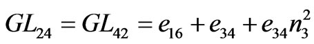 and
and 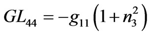 where n3 = k3/k. Therefore, the following system of two homogeneous equations must be resolved:
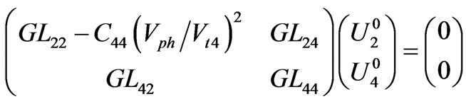 (7)
(7)
The directional cosines in Equation (7) are defined as follows: n1 ≡ 1, n2 ≡ 0 and n3 = n3. Setting the determinant of the coefficient matrix in Equation (7) equal to zero, several characteristics can be found such as a suitable phase velocity Vph satisfying boundary conditions discussed in the following section and four polynomial roots n3(p)(Vph), as well as the functions U20(Vph) and U40(Vph). It is thought that it is convenient to utilize the functions U20(Vph) and U40(Vph) in the following forms: 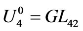 and
and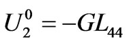 .
.
Using the piezoelectric constants 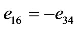 for direction [101], the following polynomial can be introduced from Equation (7):
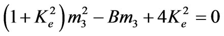 with
with 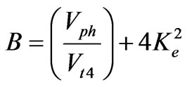 (8)
(8)
where m3 = 1 + n32. In Equation (8), Ke2 is the static coefficient of the electromechanical coupling (CEMC):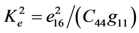 . Note that the speed VSH of the bulk SH-wave reads:
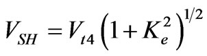 (9)
(9)
It is obvious that Equation (8) has two roots:
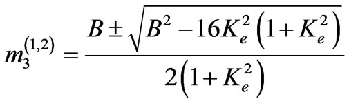 (10)
(10)
Hence, four polynomial roots (eigenvalues) of Equation (7) are as follows:
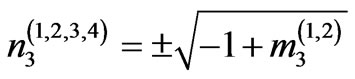 (11)
(11)
It is noted that the eigenvector {U20, U40} in Equation (7) can be obtained for each eigenvalue n3.
Note that all complex roots can be calculated when the expression B2 – 16Ke2(1 + Ke2) under square root in Equation (10) is negative. This fulfills for Vph < VK obtained from the following equation B2 – 16Ke2(1 + Ke2) = 0 and defined by the following formula:
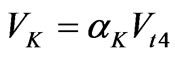 with
with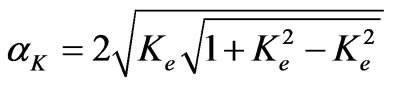 (12)
(12)
It is clearly seen that both the factor αK in Equation (12) and the function f(Ke2) = (1 + Ke2)1/2 in Equation (9) are functions of the CEMC Ke2. Discussions about behavior of polynomial roots and the function αk can be found in Ref. [10]. However, it is necessary to briefly discuss that only complex polynomial roots can exist for Vph < VK and that for Ke2 < K02 (K02 = 1/3) there are all imaginary roots for Vph > VK, but a very large Ke2 > K02 gives real roots for Vph > VK. It is noted that only complex/imaginary roots with negative/positive imaginary parts for medium I/II in figure 1 are chosen in order to have wave damping towards the each half-space depth from the common interface. Probably, surface waves cannot be found in the cubic crystals with a large Ke2 > 1/3 in the Vph-range: VK < Vph < VSH. It is thought that a large Ke2 can be observed in complex compounds, as well as in simple materials including piezoelectric cubic crystals. For instance, a single ferroelectric tetragonal (T) to paraelectric cubic phase transition is observed in the classic ferroelectric PbTiO3 with increase in temperature or pressure, according to the recent results obtained in Ref. [11].
3. Boundary Conditions for Interfacial SH-Waves
There is single boundary at x3 = 0 in figure 1 representing the interface between two half-spaces, at which suitable requirements can be chosen. These several requirements called boundary conditions must be satisfied for propagation of the interfacial SH-waves, which must damp from the common interface towards depth of each half-space. Using the coordinate system in figure 1, only eigenvalues with negative imaginary parts must be chosen for the medium with negative values of the x3-axis. Also, only eigenvalues with positive imaginary parts must be chosen for the medium with x3 > 0. There are two mechanical boundary condition such as equality of the mechanical displacements U2 (U2I = U2II) where
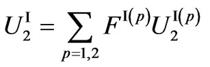 and
and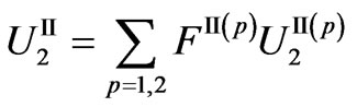 (13)
(13)
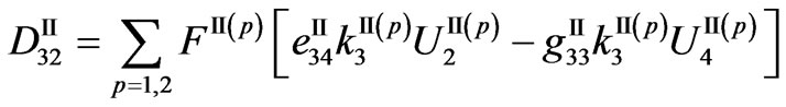
and equality of the normal components of the stress tensor, TI32 = TII32, where

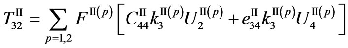 (14)
(14)
Note that the superscripts “I” and “II” are for the first and second media, respectively. There are two electrical boundary conditions at x3 = 0: continuity of the normal component D3 of the electrical displacements, where
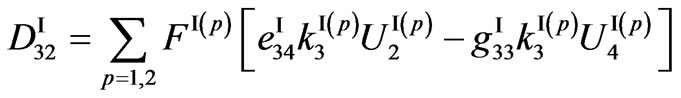
 (15)
(15)
and continuity of the electrical potential U4 = f (f I = f II) where
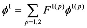 and
and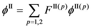 (16)
(16)
Therefore, the boundary-condition determinant (BCD4) of fourth-order for the interfacial waves can be written using the following four homogeneous equations:
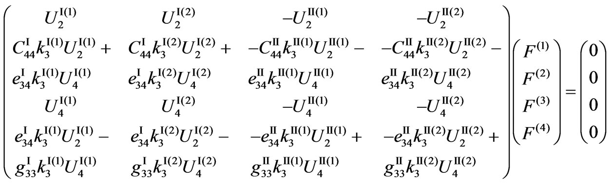 (17)
(17)
Using the mechanical and electrical boundary conditions at x3 = 0 such as U2I = U2II, σ32I = σ32II, f I = 0 and f II = 0, the BCD4 of the coefficient matrix for the case of metallized interface can be obtained from the following equations:
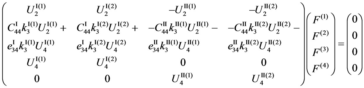 (18)
(18)
The complete mechanical displacement U2Σ and electrical potential φΣ = U4Σ are written for each half-space as follows:
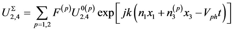 (19)
(19)
The corresponding weight functions F(p) are found from Equations (17) and (18), which can give the same eigenvectors (U20(1), U40(1)) and (U20(2), U40(2)) for two equal eigenvalues n3(1) = n3(2) in each half-space and hence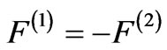 . It is obvious that the weight factors
  will zero the complete mechanical displacement U2Σ and electrical potential φΣ in Equations (17) and (18). That can mean that they are “latent” characteristics. On the other hand, eigenvalues n3(1) ≠ n3(2) give corresponding eigenvectors (U20(1), U40(1)) and (U20(2), U40(2)) as well as
 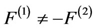 resulting in non-zero displacements, which must be equal at the interface damping towards the depth of both media.
4. Results and Discussions
Acoustic wave propagation along the common interface between two dissimilar piezoelectric materials has peculiarities concerning choice of suitable materials to support the SH-waves. Maerfeld and Tournois in Ref. [1] have found that the interfacial SH-waves can always exist in suitable cuts of the transversely-isotropic materials, in which the surface BG-waves can also exist. Note that the velocity of interfacial Maerfeld-Tournois (MT) wave in similar materials with opposite polarization coincides with the velocity VBGm of the surface BG-wave propagating along the metallized surface of transversely-isotropic piezoelectrics, VBGm = VSH[1 – (Ke2/(1 + Ke2))2]1/2 [2]. This can mean that some similarity occurs between the interfacial MT-waves and surface BG-waves when the transversely-isotropic materials are treated. The velocity VBG of the BG-wave with the non-metallized surface is calculated with the following formula: VBG = VSH{1 – (Ke2/[(1 + Ke2)(1 + g11/g0)])2}1/2. Due to the fact that the surface Bg-waves and the interfacial MT-waves cannot exist in piezoelectric cubic crystals, the existence of new surface SH-waves called the ultrasonic surface Zakharenko waves (USZWs) was studied in the cubic crystals (see Ref. [10]) and the new interfacial SH-wave existence is studied in this paper.
The material constants and USZW characteristics for several cubic crystals with strong piezoelectric effect are listed in tables 1 and Table 2, respectively. It was found that the velocities of the new interfacial waves with metallized interface are coincide with the VBGm. This is also true for the velocities of the interfacial MT-waves and the USZWs on the metallized surface. That illuminates common wave speed characteristics among the different waves. Therefore, they can be calculated with the for mula for VBGm written above. It is noted that all the above mentioned velocities were calculated using different boundary-condition determinants. However, it was found that the velocity of the USZWs on the non-metallized surface cannot be calculated with the formula for VBG. For instance, the formula for VBG gives the value of V1 ~ 848.6 m/s instead of the table 2 value of Vnew ~ 848.1 m/s for Tl3TaSe4. The velocity V1 is significantly closer to the velocity vSH of bulk waves (see table 2) than the true velocity Vnew obtained numerically. Therefore, it is obvious that the penetration depth of the USZWs in piezoelectric cubic crystals will be smaller than that for the surface BG-waves in the transversely-isotropic monocrystals. This is an advantage of the USZWs. Note that all the wave characteristics were calculated with an accuracy of about 1 μm/s. This is useful and allows the distinguishing of Vph-solutions when they are close to each other.
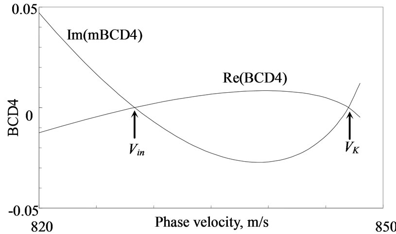
Figure 2 shows the phase velocity solutions for the new interfacial waves (Vin) in the Chalcogenides Tl3TaSe4 and Tl3VS4 pertaining to class `43m, Vin = Vnew,m, using similar materials for the acoustic systems with opposite polarization and both the metallized and non-metallized interfaces, Vin = Vin,m. The finding of Vin for the cubic crystals Bi12SiO20 and Bi12GeO20 of class 23 is shown in figure 3 using the same configuration consisting of
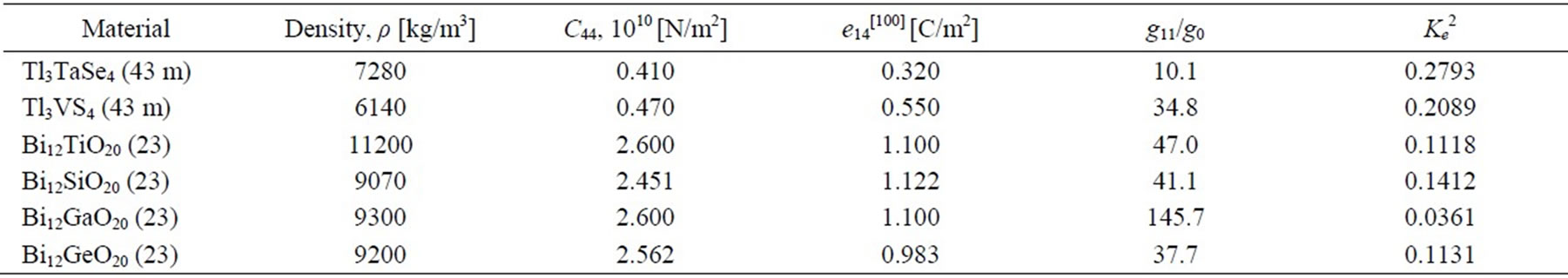
Table 1. The material constants: the material density ρ, non-zero elastic C44, piezoelectric e14 and dielectric g11 constants for the SH-wave propagation in the piezoelectric cubic crystals [7,8,9] with the strong piezoelectric effect. Note that the dielectric constant of a vacuum is g0 = 0.08854 [10–10 F/m]; e16[101] = -e14[100] and e34[101] = e14[100]. The coefficient of electromechanical coupling (CEMC) Ke2 in the last column was calculated with the following formula: Ke2 = e142/(c44g11).
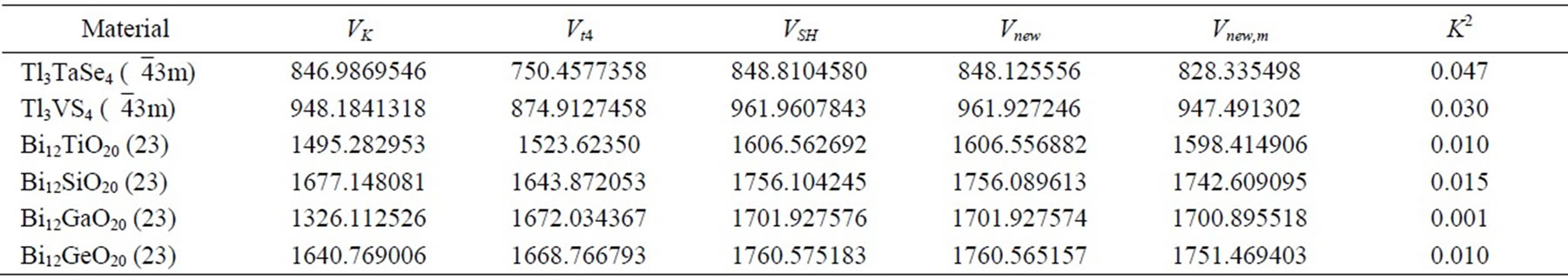
Table 2. The wave characteristics: the velocities vK, Vt4, and vSH (all in m/s) as well as the velocities Vnew and Vnew,m of the new-SH-SAWs (USZWs) on the free and metallized surfaces, respectively, for the piezoelectric cubic crystals with the strong piezoelectric effect when the wave propagation is along direction [101]. The last column lists the non-dimensional values of the CEMC K2 calculated with formula (20). Note that one can calculate that VBG(Bi12SiO20) = 1756.096654 m/s is larger than Vnew(Bi12SiO20) and the same occurs for VBG(Bi12GeO20) = 1760.569112 m/s.
 (a)
(a)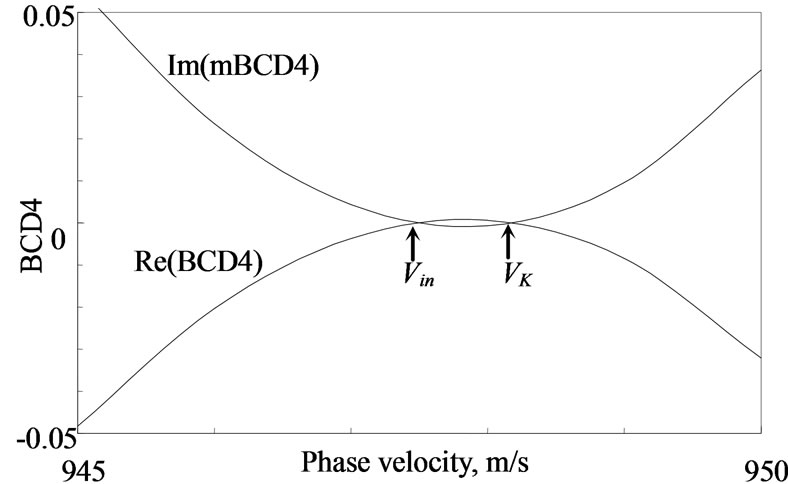 (b)
(b)
Figure 2. The dependence of the boundary-condition determinants (BCD4) on the phase velocity Vph for direction [101] of the new interfacial wave (Vin) propagation in the systems Tl3TaSe4 (a) and Tl3VS4 (b) with opposite polarization using the interface metallization (mBCD4) and non-metallized interface (BCD4).
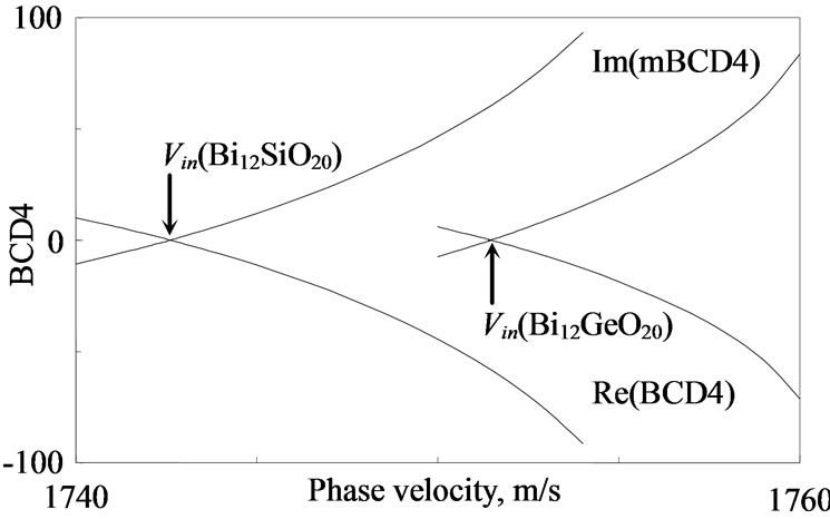
Figure 3. The dependence of the boundary-condition determinants (BCD4) on the phase velocity Vph for direction [101] of the new interfacial wave (Vin) propagation in the systems Bi12SiO20 and Bi12GeO20 with opposite polarization using the interface metallization (mBCD4) and non-metallized interface (BCD4).
similar materials. It was thought that the crystals Bi12SiO20 and Bi12GeO20 can be used together to support propagation of the new interfacial waves in dissimilar material, because their bulk SH velocities vSH are relatively close to each other and also true for Vin. The BCD4 behaviors for the dissimilar materials are shown in figure 4, in which it is clearly seen that there are solutions for the Bi12SiO20/Bi12GeO20 configuration. Using the normal polarization for the crystals Bi12SiO20 and Bi12GeO20, only the velocity Vin,m for the metallized interface was found having the value of Vin,m = 1746.926119 m/s. The Vin,m value is larger than the value of Vnew,m for Bi12SiO20 listed in table 2 and smaller than the value of Vnew,m for Bi12GeO20. However, the configuration with the opposite-polarized crystals Bi12SiO20 and Bi12GeO20 demonstrates existence of both velocities Vin,m and Vin for the metallized and non-metallized interfaces, Vin,m = 1746.926119 m/s and Vin = 1747.138149 m/s. It is clearly seen that the values of Vin,m and Vin are close to each other but distinguishable in the calculations.
In the case of known values of the Vin,m and Vin, the existence of the new interfacial waves for both the electrical boundary conditions allows evaluation of the coefficient of electromechanical coupling (K2):
 (20)
(20)
The value of K2 calculated with formula (20) is very small for the crystals with the strong piezoelectric effect (see the tables) and is equal to K2 ~ 0.000243. This is only ~ 0.0243% and significantly smaller than ~ 1% for Bi12GeO20 listed in table 2. It is also noted that the interfacial wave propagation can be studied in suitable two-layer structures consisting of various cubic piezomagnetics [17,18]. Note that a study of interfacial wave propagation in non-cubic piezomagnetics was recently introduced in Ref. [19].

Figure 4. The dependence of the boundary-condition determinants (BCD4) on the phase velocity Vph for direction [101] of the new interfacial wave (Vin,m) propagation in the Bi12SiO20/Bi12GeO20 systems with normal (bold lines) and opposite polarization (normal lines) using the interface metallization (mBCD4) and non-metallized interface (BCD4).
5. Conclusions
This theoretical report was concerned with the interfacial wave propagation in cubic crystals with strong piezoelectric effect, in which the surface Bleustein-Gulyaev waves cannot exist. This was recently mentioned in Ref. [5] by Gulyaev and Hickernell. It was illuminated that the new interfacial waves can always be found in acoustic systems consisting of two half-spaces representing identical materials with opposite polarization. Also, the new interfacial waves can exist in dissimilar materials solidly coupled at their interface, for instance, in the Bi12SiO20/Bi12GeO20 system, using the electrical boundary conditions of both the metallized and non-metallized interfaces. Note that the theoretically obtained results can be useful to design experiments for measuring interfacial properties by the microwave technologies.
6. Acknowledgements
The author is grateful to the Referees for useful notes.
REFERENCES
- C. Maerfeld and P. Tournois, “Pure Shear Elastic Surface Wave Guide by the Interface of Two Semi-Infinite Media,” Applied Physics Letters, Vol. 19, No. 4, 1971, pp. 117-118.
- J. L. Bleustein, “A New Surface Wave in Piezoelectric Materials,” Applied Physics Letters, Vol. 13, No.12, 1968, pp.412-413.
- Yu. V. Gulyaev, “Electroacoustic Surface Waves in Solids,” Soviet Physics Journal of Experimental and Theoretical Physics Letters, Vol. 9, No.1, 1969, pp. 37-38.
- G. A. Maugin, “Elastic Surface Waves with Transverse Horizontal Polarization,” Advances in Applied Mechanics, Vol. 23, 1983, pp. 373-434.
- Yu. V. Gulyaev and F. S. Hickernell, “Acoustoelectronics: History, Present State, and New Ideas for a New Era,” Acoustical Physics Reports, Vol.51, No.1, 2005, pp. 101-110.
- G. G. Kessenikh and L. A. Shuvalov, “Transverse Surface Waves in Piezoelectric Crystals of Classes 622 and 422,” Ferroelectrics, Vol. 42, No. 1, 1982, pp. 149-152.
- J. Henaff, M. Feldmann and M. A. Kirov, “Piezoelectric Crystals for Surface Acoustic Waves (Quartz, LiNbO3, LiTaO3, Tl3VS4, Tl3TaSe4, AlPO4, GaAs),” Ferroelectrics, Vol.42, No.1, 1982, pp. 161-185.
- A. A. Zakharenko, “Love Type Waves in Layered Systems Consisting of Two Piezoelectric Cubic Crystals,” Journal of Sound and Vibration, Vol. 285, No. 4-5, 2005, pp. 877-886.
- V. P. Kamenov, Y. Hu, E. Shamonina, K. H. Ringhofer and V. Ya. Gayvoronsky, “Two-Wave Mixing in (111)-Cut Bi12SiO20 and Bi12TiO20 Crystals: Characterization and Comparison with the General Orientation,” Physical Review E, Vol. 62, No. 2, 2000, pp. 2863-2870.
- A. A. Zakharenko, “New Solutions of Shear Waves in Piezoelectric Cubic Crystals,” Journal of Zhejiang University SCIENCE A, Vol. 8, No. 4, 2007, pp. 669-674.
- Zh. Wu and R. E. Cohen, “Pressure-Induced Anomalous Phase Transitions and Colossal Enhancement of Piezoelectricity in PbTiO3,” Physical Review Letters, Vol. 95, No. 3, 2005, p. 4.
- R. C. Pohanka and P. L. Smith, “Recent Advances in Piezoelectric Ceramics”, Marcel Dekker, New York, 1988.
- U. Gösele and Q. Y. Tong, “Semiconductor Wafer Bonding,” Annual Review of Material Science, Vol. 28, 1998, pp. 215-241.
- M. Alexe and U. Gösele, “Wafer Bonding,” Springer, Berlin, 2003.
- C. A. Harper, “Handbook of Plastics, Elastomers and Composites,” 3rd Edition, McGraw-Hill, New York, 1996.
- C. Ageorges and L. Ye, “Fusion Bonding of Polymer Composites,” Springer, Berlin, 2002.
- A. A. Zakharenko, “First Evidence of Surface SH-Wave Propagation in Cubic Piezomagnetics,” Journal of Electromagnetic Analysis and Applications, Vol. 2, No. 5, 2010, pp. 287-296.
- Y. Huang, X.-F. Li and K. Y. Lee, “Interfacial Shear Horizontal (SH) Waves Propagating in a Two-Phase Piezoelectric/Piezomagnetic Structure with an Imperfect Interface,” Philosophical Magazine Letters, Vol. 89, No. 2, 2009, pp. 95-103.
- A. K. Soh and J. X. Liu, “Interfacial Shear Horizontal Waves in a Piezoelectric-Piezomagnetic Bi-Material,” Philosophical Magazine Letters, Vol. 86, No. 1, 2006, pp. 31-35.