Journal of Electromagnetic Analysis and Applications
Vol. 3 No. 2 (2011) , Article ID: 4123 , 9 pages DOI:10.4236/jemaa.2011.32009
Modelling and Artificial Intelligence-Based Control of Electrode System for an Electric Arc Furnace
![]()
Department of Electrical Engineering, Islamic Azad University, Abadan, Iran.
Email: mahmood_moghadasian@yahoo.com
Received July 13th, 2010; revised August 23rd, 2010; accepted January 8th, 2011
Keywords: Electric Arc Furnace, Electrode, PI Controller, Fuzzy Logic, Genetic Algorithm
ABSTRACT
This paper presents a new application of a genetic-fuzzy control system which controls the input energy to a three phase electric arc furnace. Graphite electrodes are used to convert electrical energy into heat via phase electric arcs. Constant arc length is desirable as it implies steady energy transfer from the graphite electrodes to the metallic charge in the furnace bath. With the charge level constantly changing, the electrodes must be able to adjust for the arc length to remain constant. A fuzzy PI controller tuned with genetic algorithms has been developed to be responsible for the vertical adjustment of the electrode tip displacement according to specified set-points to ensure that the arc lengths remain as constant as possible. The simulation results show that the system performances are satisfactory using the proposed method.
1. Introduction
The production of steel by Electric Arc Furnaces (EAF) has steadily expanded during the past few decades. The basic operating principle of such furnace has been shown in figure 1. Whether in the AC or the DC type, the electric arcs are struck from one or more electrodes to metallic charges.
Electric arc furnaces are used to produce steel by melting scrap together with some other raw materials using an electrical supply as the main energy input [1]. The graphite electrodes connected to the electrical supply are used to convert electrical energy into extensive heat by means of high current electric arcs drawn between the electrode rips and the metallic charge [2]. The electric arcs cause the solid scrap to be transformed into the liquid state [3]. The molten steel is then converted to a specified grade with addition of chemical substances by means of oxygen blowing and carbon injection.
Electric current in the graphite electrodes will remain constant if the length of the electric arcs is constant [4].
Due to power system problems attributed to EAFs, there has been an ongoing need for models that can be used to represent this type of nonlinear load in order to better assess the impact to EAF installations, whether existing, up-graded or new. The problem is complicated by the fact that the EAF voltage vs. current characteristic is essentially much nonlinear.
Several known approaches for modeling and predicting the behavior of EAFs include the use of nonlinear resistance, mathematical, stochastic and system identification approaches, as well as methods based on v–i characteristic,
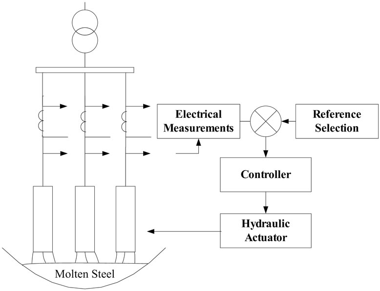
Figure 1. Electrode position control system.
power or current/voltage sources and a combination of thereof.
Tap changes on the furnace transformer are the main source for the controlling electrical power. However constant arc lengths imply that the power input to the arc furnace load is stable around the set-point determined by the tap changer, which results in effective production. Arc current is mainly used as the control variable in an industrial electric arc furnace because of its direct relation with the length of the electric arcs and some other advantages. In this work a fuzzy PI controller modified by genetic algorithms has been presented to adjust the position of the electrodes of EAF.
Early EAF models [5], most often were based on explicit mathematical equations and empirical relations which did not directly incorporate the quasi-stochastic nature of EAF operation [6]. One interesting approach, however, was the use of an analog approach [7] to represent the furnace in system studies. Modeling methods based on explicit mathematical equations are reported in [8,9]. These techniques involve the use of a dynamic arc model and are developed using a differential equation approach that is based on the principle of conservation of energy.
Several studies have modeled the EAF in terms of a controlled voltage source [10,11]. With this approach, the random operation of the arc has been modeled by stochastically modifying its v–i characteristics. A modeling approach using a time domain controlled voltage source is presented in [12]. This model is based on a piece-wise linear approximation of the v–i characteristic of the arc furnace load. By considering the active power consumed by the load, the load model is dependent on the operating conditions of the furnace.
More recently, adaptive data-driven approaches have been used for EAF modeling [13-17]. These are model structures; also refer to as black-box methodologies that can be used to describe any nonlinear dynamics. These model structures include neural networks, radial basis networks, fuzzy rule based networks, and wavelet networks [18]. Neural network based approaches, including radial basis function and multi-layer perceptron, both using data collected from operational EAF are reported in [13,14]. A modeling approach based on extended Kalman filters is described in [15]. Works in [16,17] relate to use of adaptive neuro-fuzzy inference mechanism for simulation and modeling of both EAF and its regulator control loop.
Furthermore, a number of modeling techniques have used the actual EAF measurements together with parametric system identification approaches. [19] reported a model using auto regression. This method uses actual measurements and an autoregressive model to represent the random variation of the arc length. A model using parametric system identification techniques is presented in [20]. This method used data collected from an operating EAF and both AR (auto regression) and ARX (auto regression with auxiliary input) models to explain the dynamics of electric arc furnaces [36].
An electric arc is defined as discharging gas between two electrodes (anode and cathode) which are connected to a voltage source [21]. In an electric arc furnace process, the main electrode consists of graphite material. The electrical energy input will be applied to the graphite electrodes. The scrap metal and other raw materials to be melted constitute the other electrode. The discharging arc is also known as plasma and consists of negatively charged electrons and positive gas ions [22].
Recently, fuzzy inference system (FIS) has emerged as one of the most active and fruitful fields for research in the application of fuzzy set theory and many practical applications to industrial process, as well as studies on the theory itself, have been reported in many works. In practice, FIS usually used the following linguistic variables: error and change in error. It is difficult to simultaneously take into account both the transient response and the steady-state response by the conventional method.
In order to get a good performance, we adjust the scaling factors of FIS. From the simulation, we see that the proposed FIS has the ability to improve the performance of the control system. But the scaling factors are set from the experiment. It is trial-and-error and very time-consuming. Furthermore, we cannot make sure that the selected control parameters will provide the system with a high control performance. In this paper, we propose a method to select the control the scaling factors by genetic algorithms based on some performance measures of the system’s response.
This paper is organized as follows: explicit mathematical equations and a differential equation approach that is based on the principle of conservation of energy which models the EAF in the terms of a controlled voltage source is described in Section 2. In Section 3, a fuzzy PI control system tuned with genetic algorithms is employed to maintain the arc length as constant as possible and minimizes the input energy to the EAF. Arc current, resistance and arc voltage are shown in Section 4, where simulation results of variable arc lengths on the inputs of the electrical model are presented. Finally, Section 5 concludes the paper.
2. The Eaf Model
2.1. Impedance Model
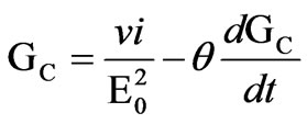
A three-phase electric arc furnace can be modeled as an electric circuit with the arc being represented by a variable resistance [26]. Such a model will be very advantageous because the highly nonlinear electric arc has to function as a variable three-phase load. Two well known and widely used arc impedance models are the Mayr model, which is a suitable representation of an arc for low currents, and the Cassie model, which yields good results for arcs with high currents. These models are usually expressed in conductance rather than arc resistance because of extremely low values for arc resistance. The Cassie equation is given by
 (1)
(1)
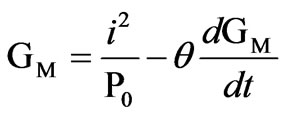
and the Mayr equation by
 (2)
(2)
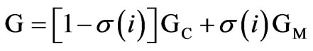
These relatively simple differential equation models are based on simplifications of principal power-loss mechanisms and energy storage in the arc column. They provide a qualitative understanding of the phenomenon that determines arc striking or extinction in energy-balance systems [27]. In this paper, a combined Cassie and Mayr model is used to represent the arc impedance characteristics. The two models are combined into a single model by defining a transition current I0. Cassie’s model will dominate when the arc current is bigger than I0 and when the arc current is smaller than I0, Mayr’s model dominates. However, to allow for smooth transition between the two models, a transition function σ(i) is defined, which is a function of the arc current such that the final arc conductance is given by
 (3)
(3)
where GC and GM are the conductance given by (1) and (2), respectively. The transition factor varies between zero and unity and should be a monotonically decreasing function when arc current increases. The transition factor is given by
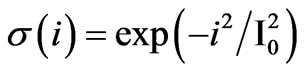 (4)
(4)
When the arc current i is small, the value of σ is close to unity and G is dominated by the Mayr conductance GM. When i is large, σ is negligible and, therefore, G is dominated by the Cassie conductance GC. (3) and (4) are combined to generate the complete Cassie-Mayr arc impedance model for a single electric arc as follow:

and
 (5)
(5)
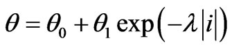
When an arc is igniting or extinguishing, the energy stored per unit volume is large compared with the energy loss per unit volume. Thus,  should be a function of the arc current i. When the arc stabilizes, error of i is small and can be represented as follow:
 (6)
(6)
where  and
and . When the arc is igniting or extinguishing, i is small and
 . When i is large,
 . The relationship between the arc length and the threshold arc voltage is given by [28]:
 (7)
(7)
The main objective is to maintain a constant RMS value for the electrical energy input. Measured arc currents are compared with specified reference values. The measured values and their errors serve as input to fuzzy inference system, which determines whether the electrodes should be raised or lowered and by how much.
2.2. The Hydraulic Actuator
Three hydraulic actuators are used in the electric arc furnace process to move each graphite electrode in vertical position to adjust the length of its electric arc [29]. Constant arc length implies constant arc current, which is the choice of control variable for controller system.
Figure 2 shows a typical hydraulic actuator configuration used for the vertical movements of electrodes. HRR is a high response regulating valve, D is a hydraulic actuator and V is a high pressure vessel. P1 and P2 are pressure pumps and T is a tank which contains 90% water and 10% oil. This is mostly a safety precaution because water will prevent the hydraulic fluid from catching fire when is close range with the electric arc furnace. The Hydraulic Actuator system can be described by six state variables as follows:
● x1 - spool position of the hydraulic distributor and
● x2 - velocity of the spool
● x3 - position of the hydraulic piston
● x4 - velocity of the piston
● x5 - pressure in the chamber above the piston in the cylinder, and
● x6 - the pressure in the chamber below the piston
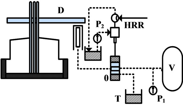
Figure 2. Hydraulic actuator system for electrode control.
The constants and variables used in this model are described in table 1. The values for these variables are obtained from industrial measurements and data [31].
3. The Fuzzy - PI Controller
The control system of an EAF includes many subsystems that play important roles in minimizing operational costs and improving production quality. The most important subsystem in an EAF control process is the electro deregulation loop through electrode positioning that has been shown in figure 3. This loop is traditionally called a “regulator loop” in the EAF technology, and the same term will be used throughout this paper. In many modern EAFs, by using smart predictive load control (SPLC), the supply of current to the electrodes is regulated to remain below the adjustable high limit. Thus, the EAF could always work with the same transformer tap and a constant current supply. On the other hand, the impedance inside the furnace and during the meltdown is always variable. Since the current is always kept limited by the SPLC, positioning the electrodes is the only way to achieve the current reference (set point). In the EAF studied, the regulator loop generates a control current going to the hydraulic actuator that controls the flow of hydraulic fluid into the cylinders that move the electrodes up/down. Each cylinder can move independently up or down and has a speed reference from its own control loop.
The current reference for each phase is currently calculated by means of a look-up table. The rows of the look-up table are associated with the progressive stages of melting. The indicator for percentage melting progress (or meltdown percentage) is calculated using the estimated values of the consumed power and scrap weight charged in the EAF. Based on the meltdown percentage, the current reference for each phase is read and adjusted. At the beginning, the current is kept low to ensure safe arc ignition. As the electrodes enter the scrap pile, the current can be increased.
The core part of the regulator loop is a fuzzy proportional–integral (FPI) controller that works on the current error for each phase, and its output is used to set the position of the electrodes through the Hydraulic Actuators. The current feedback is measured from the secondary side of the MV/LV transformer. Additionally, as the meltdown progresses from the initial melting stages to the final refining stages, the FPI coefficients are tuned by means of an off-line genetic algorithm system [37].
Since the fuzzy controller is basically an input/output static nonlinear mapping, we can write the controller action in the form
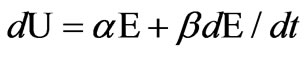 (8)
(8)
Where  and
and  are nonlinear coefficients or gain factors. Integrating both sides results in equation
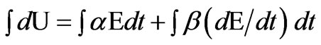 (9)
(9)

Table 1. Constants and variables in the hydraulic model.
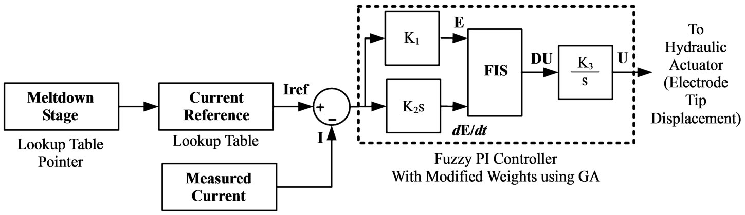
Figure 3. The regulator control loop for one phase.
or
 (10)
(10)
which is nothing but a fuzzy PI controller with nonlinear gain factor. The  and
and  (or equally, K1, K2 and K3) coefficients of this controller are determined using the genetic algorithms as explained later.
3.1. Fuzzy Inference System
Fuzzy inference systems (FIS) are designed in an intuitive manner and can have as many inputs and outputs as necessary. In this case, the FIS is a part of the FPI system which controls vertical adjustment of the electrode tip displacement. A zero order Takagi-Sugeno fuzzy logic controller [24] is used. The inputs to the proposed FIS are the electric arc current error in per unit  and its derivation
 . The universe of discourse for the variable I is [-0.3; -0.3] and for
  is [-0.1; 0.1]. Both universes of discourse are divided into five fuzzy sets: negative large (NL), negative small (NS), zero (Z), and positive small (PS) and positive large (PL). The membership functions employed for these fuzzy sets are triangular, as shown in figures 4 and 5. With these membership functions distribution the 5 × 5 rules matrix shown in table 2 is defined.
The output of the FIS is the vertical adjustment of the electrode tip displacement which is calculated using
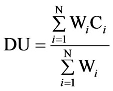 (11)
(11)
3.2. Genetic Algorithms
The input and output scale factors of the FPI controller (K1, K2 and K3 in figure 3) are tuned using an off-line genetic algorithm system to minimize the EAF phase current (I) error. Genetic Algorithms (GAs) are based on an analogy to the genetic code in our own DNA (deoxy-
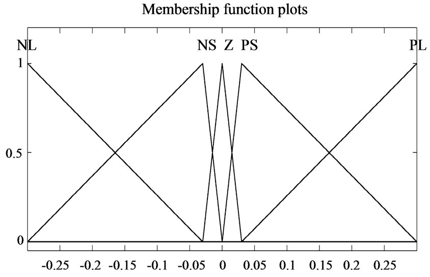
Figure 4. Membership function for EI.
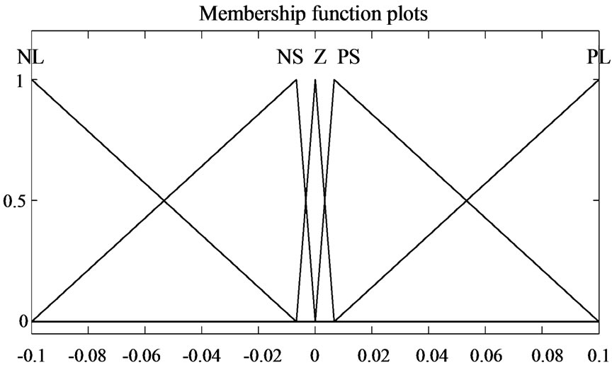
Figure 5. Membership function for .
.
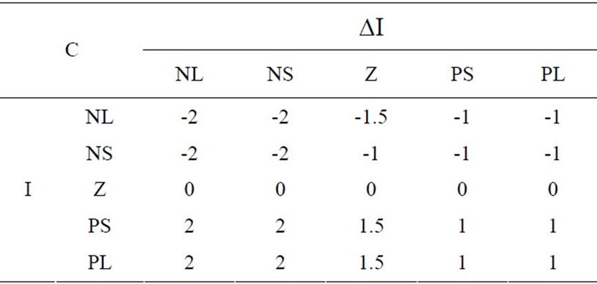
Table 2. Rules matrix for the Electrode Tip Displacement ( ).
).
ribonucleic acid) structure, where its coded chromosome is composed of many genes [32,33]. GA is a stochastic global search optimization technique based on the mechanisms of natural selection. GA has been recognized as an effective technique to solve optimization problems. Compared with other optimization techniques, GA is superior in avoiding local minima which is a common aspect of nonlinear systems.
Furthermore GA is a derivative-free optimization technique which makes it more attractive for applications that involve nonsmooth or noisy signals. Generally GA consists of three main stages: selection, crossover and mutation.
Selection: in this stage individuals of the initial population are selected for reproduction with probability proportional to their fitness value. The purpose of this operation is to obtain a mating pool with the fittest individuals selected according to a probabilistic rule that allows these individuals to be mated into the new population.
Crossover: after the selection stage the genetic crossover operation is then applied between parent pairs from the mating pool to generate new individuals or offsprings which acquire good features from their parents. This crossover operation is performed with a crossover probability (Pc). The crossover operation can be a one-point or a double-point.
Mutation: the last operation is genetic mutation which takes place after the crossover operation. The application of genetic mutation introduces a change in the offspring bit string to produce new chromosomes which may represent a solution of the problem and at the same time avoid the population falling into a local optimal point. The mutation operation is performed with mutation probability (Pm) which is usually low to preserve good chromosomes and to mimic real life where mutation rarely happens. The application of these three basic operations allows the creation of new individuals which may be better than their parents. This algorithm is repeated for many generations and finally stops when reaching individuals which provide an optimum solution to the problem.
Due to its effectiveness in searching nonlinear and multi-dimensional search spaces, GA can be applied to tuning of the FPI controller gains to cope with the nonlinearities existing in the EAF model. In this case the fitness function used to evaluate the individuals of each generation can be chosen to be the integral with time of absolute error (ITAE). The mathematical expression of this cost function, which is the function minimized by the GA, can be written as
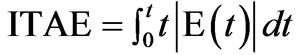 (12)
(12)
or equally for the discrete systems
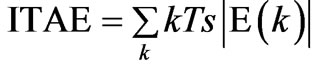 (13)
(13)
This function is used as the GA evolution criteria and has the advantage of avoiding cancellation of positive and negative errors. During the search process, the GA looks for the optimal setting of the FPI controller gains which minimize the cost function. Individuals with low ITAE are considered as the fittest. Each chromosome represents a solution of the problem and hence it consists of three genes: K1, K2 and K3. So the chromosome vector is [K1, K2, K3]. The range of each gain must be specified. The genetic algorithm parameters chosen for the tuning purpose and its architecture are shown in table 3 and figure 6.
The optimum values for the K1, K2 and K3 were obtained using a computer program written in MATLAB for the GA. This process executes with three different operators at bit level. Twenty nine of the K1 – K3 original population sets were determined at random. K1 and K2 consisted of 5 bits and K3 consisted of 6 bits. The fitness values were obtained from the error of I value (EI).
These values were then used as the fitness function and GA found the values of FPI controller to minimize the EI parameter. These values are: K1 = 0.02, K2 = 5.36 and K3 = 23.54.
4. Simulation Results
In an electric arc furnace process the distances between the electrode tips and the metallic charge is highly variable due to the random nature of the scrap. The electrical quantities are simulated here with variable arc lengths on the inputs of the electrical model. Note that these variations are completely random in practice.
Arc current, resistance and arc voltage are the interesting variables to illustrate the behavior of an electric arc furnace for variable arc lengths. For this specific simulation, the arc lengths of phase 2 and 3 are kept constant at 1 cm. The arc length on phase 1 is varied for 0.1 seconds. The arc length applied to phase 1 for this simulation is illustrated in figure 7. Note time instances 0.03 and 0.07s when the arc length changes.
The simulated arc current and resistance of phase 1 are shown in figures 8-9, respectively. The arc current of phase 1 decreases almost with 1KA (RMS value) if the arc length is changed from 1 cm to 10 cm. the arc resistance for the same step in arc length increases from about 0.015 to 0.05 Ω.
The simulated arc voltage of phase 1 is shown in figure 10. The arc voltage increases significantly when the arc length is changed from 1 cm to 10 cm and decreases when the arc length decreases.
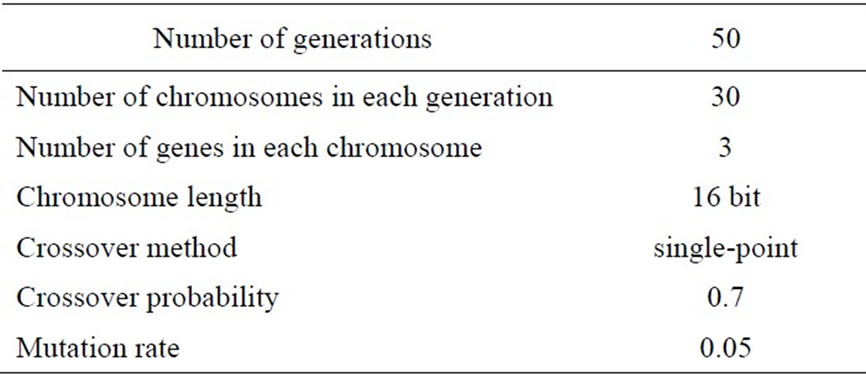
Table 3. Genetic algorithm parameters.
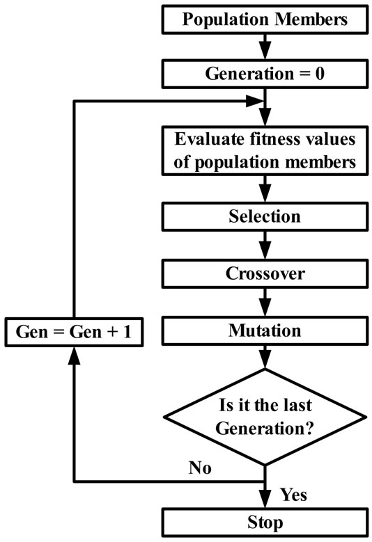
Figure 6. The flow chart of the GA.
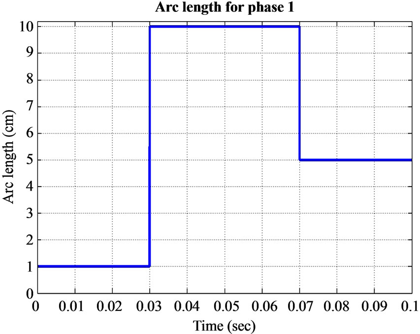
Figure 7. Variable arc length applied on phase 1. The arc length on phase 2 and 3 are constant at 1 cm.
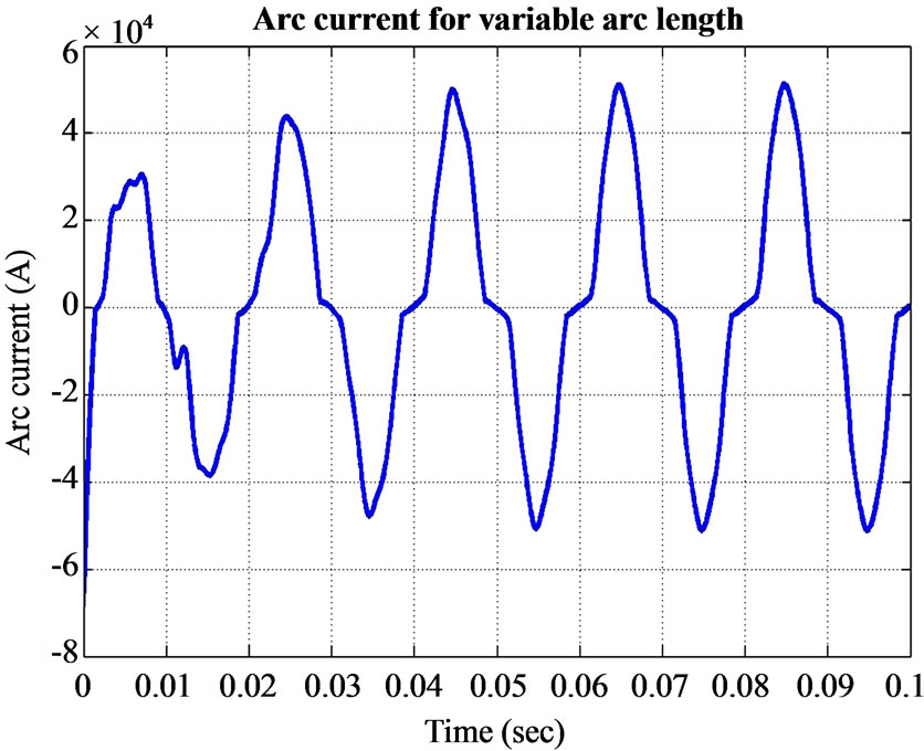
Figure 8. Simulated arc current obtained with the derived electrical model.
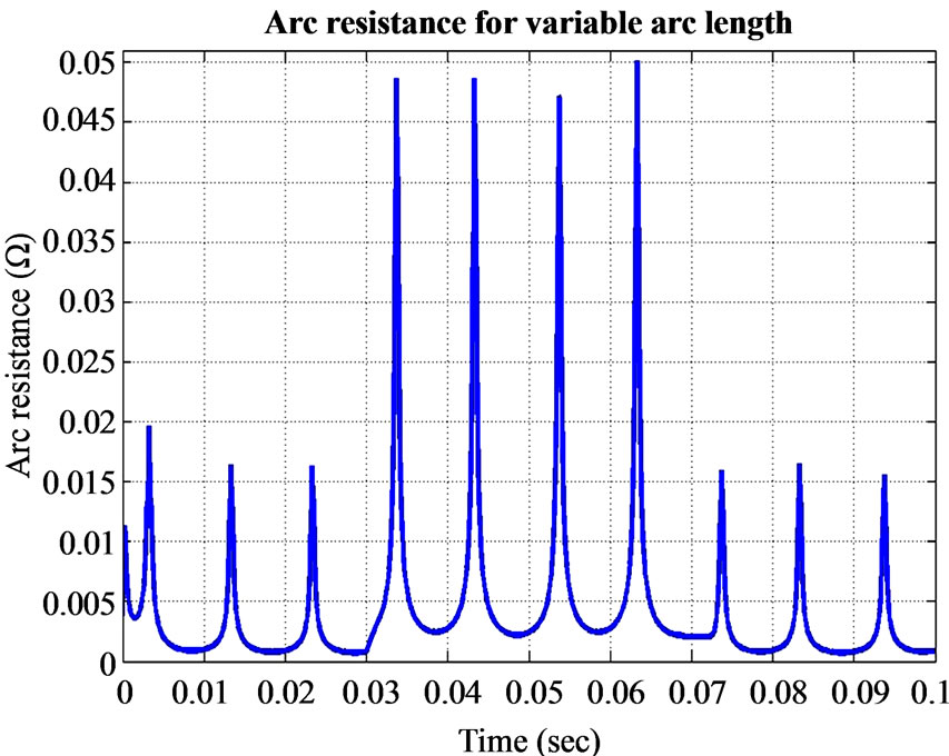
Figure 9. Simulated arc resistance.
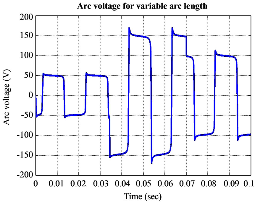
Figure 10. Simulated arc voltage.
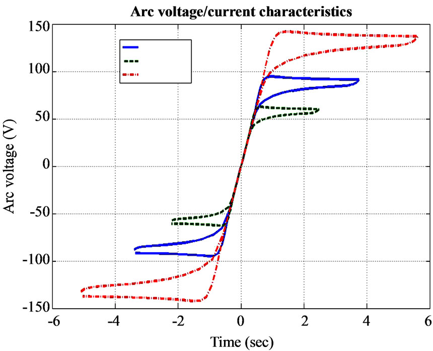
Figure 11. Arc voltage vs. arc current on phase 1.
The arc current vs. arc voltage diagram for phase 1 is illustrated in figure 11. The arc length in figure 7 has three different values which relate to three separate voltage/current characteristics.
5. Conclusion
This paper describes a fuzzy PI (FPI) controller with modified weights to run an electric arc furnace (EAF) system. The weights determination of this controller was done using the genetic algorithms (GA). The purpose of such controller is to maintain the arc length as constant as possible by adjusting the vertical displacement of the electrodes of the EAF.
The electrode system modeled in this paper is motivated by the need for constant electrical power input. Three-phase electrical arc current is used as inputs for the derived model. Measured arc current is continuously compared with desired set-points for control purposes. The controlled electrical arc current together with arc impedance and arc voltage were used to investigate the electrical properties of a three-phase electric arc furnace.
The complete model consists of the electrical supply, three hydraulic actuators and the three phase electric arcs. The electrical supply was modeled as a three-phase circuit. Three separate hydraulic actuator models were derived, one for each phase. These models are mostly based on laws relating to science. The simulation results show the effectiveness of the proposed algorithm for the electrode tip displacement control.
REFERENCES
- S. A. Billings and H. Nicholson, “Modelling a ThreePhase Electric Arc Furnace: A Comparative Study of Control Strategies,” Applied Mathematical Modelling, vol. 1, No. 7, December 1977, pp. 355- 361. doi:10.1016/0307-904X(77)90043-9
- C. R. Taylor, “Electric Furnace Steelmaking,” Iron and Steel Society, 1985.
- S. A. Billings, F. M. Boland and H. Nicholson, “Electric Arc Furnace Modelling and Control,” Automatica, vol. 15, No. 2, March 1979, pp. 137-148. doi:10.1016/0005-1098(79)90065-7
- P. Brown and R. D. Langman, “Simulation of ClosedLoop Energy Control Applied to Arc Furnaces,” Journal of the Iron and Steel Institute, Vol. 205, No. 8, August 1967, pp. 837-847.
- J. Celada, “Electrical Analysis of the Steel Melting Arc Furnace,” Iron Steel Engineer, Vol. 70, No. 5, May 1993, pp. 35-39.
- B. Danai and J. D. Lavers, “Statistical Analysis of Electric Arc Furnace Parameter Variations,” IEE Proceedings of Generation, Transmission and Distribution, Vol. 132, No. 2, March 1985, pp. 82-93.
- R. C. Dugan, “Simulation of Arc Furnace Power Systems,” IEEE Transactions on Industry and Application, Vol. IA-16, No. 6, November 1980, pp. 813-818. doi:10.1109/TIA.1980.4503877
- E. Acha, A. Semlyen, N. Rajakovic, A harmonic domain computational package for nonlinear problems and its application to electricarcs, IEEE Trans. Power Delivery 5(July(3)) (1990) 1390-1397.
- J. G. Mayordomo, L. F. Beites, R. Asensi, M. Izzeddine, L. Zabala and J. Amantegui, “A New Frequency Domain Arc Furnace Model for Iterative Harmonic Analysis,” IEEE Transactions on Power Delivery, Vol. 12, No. 4, October 1997, pp. 1771-1778.
- H. Schau and D. Stade, “Mathematical Modeling of Three Phase Arc Furnaces,” Proceedings of International Conference on Harmonics in Power System VI, Bologna, September 1994, pp. 422-428.
- S. Varadan, E. B. Makram and A. A. Girgis, “A New Time Domain Voltage Source Model for an Arc Furnace Using EMTP,” IEEE Transactions on Power Delivery, Vol. 11, No. 3, January 1996, pp. 1685-1691. doi:10.1109/61.517535
- S. Varadan, E. B. Makram and A. A. Girgis, “A New Time Domain Voltage Source Model for an Arc Furnace Using EMTP,” IEEE Transactions on Power Delivery, Vol. 11, No. 3, July 1996, pp. 1685-1691. doi:10.1109/61.517535
- Y.-J. Liu, G. W. Chang and R.-C. Hong, “Curve-Fitting -Based Method for Modeling Voltage–Current Characteristic of an Ac Electric Arc Furnace,” Elsevier, Electric Power Systems Research, Vo. 80, No. 7, July 2010, pp. 807-814.
- A. Sadeghian and J. D. Lavers, “Application of Radial Basis Functions to Model Electric Arc Furnaces,” Proceedings of IEEE International Joint Conference on Neural Networks (IJCNN’99), vol. 6, July, 1999, pp. 3996- 4001.
- F. Wang, Z. Jin, Z. Zhu and X. Wang, “Application of Extended Kalman Filter to the Modeling of Electric Arc Furnace for Power Quality Issues,” Proceedings of the International Conference on Neural Networks and Brain (ICNN&B’05), vol. 12, No. 2, October, 2005, pp. 991- 996.
- A. Sadeghian and J. D. Lavers, “Dynamic Reconstruction of Nonlinear v–i Characteristic in Electric Arc Furnaces Using Adaptive Neuro-Fuzzy Rule-Based Networks,” Applied Soft Computing, Vol. 11, No. 1, January 2011, pp. 1448-1456
- F. Janabi-Sharifi, G. Jorjani and I. Hassanzadeh, “Using Adaptive Neurofuzzy Inference System in Developing an Electrical Arc Furnace Simulator,” Proceedings of the IEEE/ASME International Conference on Advanced Intelligent Mechatronics, 2005, pp. 1210-1215.
- J. Sjoberg, Q. Zhang, L. Ljung, A. Benveniste, B. Delyon, P. Glorennec, H. Hjal-marsson and A. Juditsky, “Nonlinear Black-Box Modeling in System Identification: A Unified Overview,” Automatica, Vol. 31, No. 12, December 1995, pp. 1691-1724. doi:10.1016/0005-1098(95)00120-8
- R. Collantes-Bellido and T. Gomez, “Identification and Modelling of a Three Phase Arc Furnace for Voltage Disturbances Imulation,” IEEE Transactions on Power Delivery, Vol. 12, No. 4, October 1997, pp. 1812-1817.
- A. S. Hauksdottir, T. Soderstrom, Y. P. Thorfinnsson and A. Gestsson, “System Identification of a Three-Phase Submerged-Arc Ferrosilicon Furnace,” IEEE Transactions on Control System Technology, Vol. 3, No. 4, December 1995, pp. 377-387. doi:10.1109/87.481962
- E. Acha and M. Madrigal, “Power system harmonics,” John Wiley & Sons, New York, 2001.
- “Electric Arcs and Flicker,” January 2004. http://www. unino. robicon. com
- A. E. Emanual and J. A. Orr, “An Improved Method of Simulation of the Arc Voltage Current Characteristics,” Proceedings of Ninth International Conference on Harmonics and Quality of Power, vol. 1, October 2000, pp. 148-154. doi:10.1109/ICHQP.2000.897015
- S. S. Venkata and B. Lee, “Development of Enhanced Electric Arc Furnace Models for Transient Analysis,” 2004. http://www.psere.wise.edu
- O. Ozgen and A. Abur, “Development of an Arc Furnace Model for Power Quality Studies,” Power Engineering Society Summer Meeting) IEEE, vol. 1, July 1999, pp. 507-555.
- T. Zheng and E. B. Makram, “An Adaptive Arc Furnace Model,” IEEE Transactions on Power Delivery, July 2000.
- K. J. Tseng, Y. Wang and D. M. Vilathgamuwa, “An Experimentally Verified Hybrid CASSIE-Mayr Electric Arc Model for Power Electronics Simulations,” IEEE Transactions on Power Electronics, vol. 12, No. 3, May 1997, pp. 429-436. doi:10.1109/63.575670
- G. C. Montanari, M. Loggini and A. Cavallini, “ArcFurnace Model for the Study of Flicker Compensation in Electrical Networks,” IEEE Transaction on Power Delivery, vol. 9, no. 4, October 1994, pp. 2026-2036.
- H. Nicholson and R. Roebuck, “Simulation and Control of Electrode Position Controllers for Electric Arc Furnaces,” Automatica, vol. 8, No. 6, November 1972, pp. 683-693.
- E. Scholtz, “Modelling for Control of a Steckel Hot Rolling Mill,” Master’s Dissertation, University of Pretoria, Pretoria, 1999.
- M. Peens, “Modelling and control of an electrode system for a three phase electric arc furnace,” Master’s dissertation, University of Pretoria, Pretoria, 2004.
- D. E. Goldberg, “Genetic Algorithms in Search, Optimization, and Machine Learning,” Addison-Wesley, Reading, 1989.
- K. C. NgY and D. J. Li, “Genetic Algorithms Applied to Fuzzy Sliding Mode Controller Design,” First International Conference on Genetic Algorithms in Engineering Systems: Innovations and Applications, Sheffield, 1995, pp. 220-225.
- R. Dimeo and K. Y. Lee, “The Use of a Genetic Algorithm in Power Plant Control System Design,” IEEE Proceeding of the 34th Conference on Decision & Control, 1995, pp. 737-742.
- Proceedings of First IEE/IEEE International Conference on Genetic Algorithms in Engineering System, Innovations and Applications, Sheffied, September, pp. 220-225.
- A. Sadeghiana and J. D. Lavers, “Dynamic Reconstruction of Nonlinear v–i Characteristic in Electricarc Furnaces Using Adaptive Neuro-Fuzzy Rule-Based Networks,” Applied Soft Computing, Vol. 11, No. 1, January 2011, pp. 1448-1456. doi:10.1016/j.asoc.2010.04.016
- F. Janabi-Sharifi and G. Jorjani, “An Adaptive System for Modeling and Simulation of Electrical Arc Furnaces,” Control Engineering Practice 17, Elsevier, 2009, pp. 1202-1219.
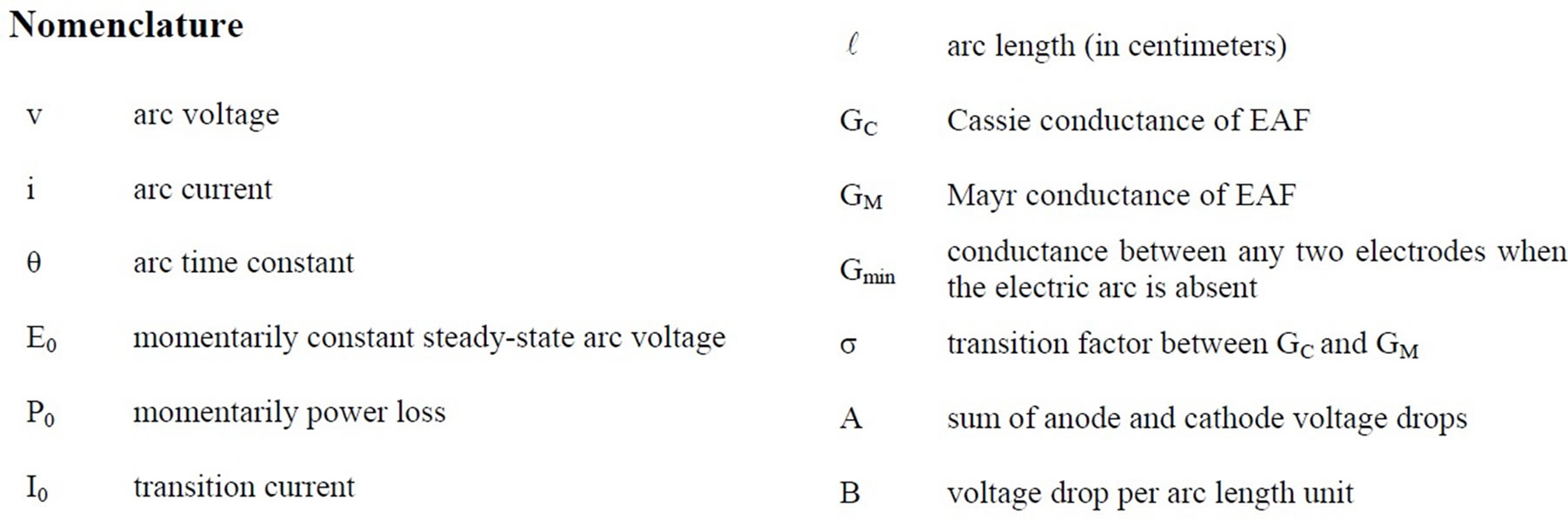
Nomenclature
NOTES
This work was supported by the research center of Islamic Azad University, Abadan branch, Abadan, Iran.