Journal of Electromagnetic Analysis and Applications
Vol. 2 No. 6 (2010) , Article ID: 2148 , 10 pages DOI:10.4236/jemaa.2010.26047
Drive and Control of Electromagnetic Drive Module on Reciprocally Rotating Disc Used for Micro-Gyroscope
![]()
Department of Mechanical Engineering, National Cheng Kung University, Tainan, Taiwan, China.
Email: nortren@mail.ncku.edu.tw
Received February 3rd, 2010; revised April 7th, 2010; accepted April 22nd, 2010.
Keywords: Micro-Gyroscope, Electromagnetic Pole, Anti-Collision, Drive Circuit
ABSTRACT
An innovative 3-phase AC (Alternative Current) drive circuit for the seismic disc in micro-gyroscopes is designed and verified by computer simulations and experiments. The in-plane dynamic model of the seismic disc with mass eccentricity and air gap against the centre bearing and the mathematic expression of two sinusoidal magnetic fields are developed respectively. In order to prevent the seismic disc from collision with the centre bearing and the EM (Electromagnetic) poles, an anti-collision controller is established by employing two Look-up tables which define the intensity of the applied current to the EM poles. Self-sensing technique is included to measure the real-time offset of the disc by two orthogonal pairs of EM poles, without any additional sensors. The drive circuit under SPWM (Sinusoidal Pulse Width Modulation) operation and the anti-collision strategy are verified by intensive computer simulations via commercial software, OrCAD 9, and experiments.
1. Introduction
By applying the Coriolis principle, the micro-gyroscope is used to detect and measure the exerted angular excitations [1,2]. The performance of the micro-gyroscope, such as resolution, sensitivity and measurement range, is limited by a few factors, for example, fabrication imperfection, frequency mismatch, and maximum rotational speed of the seismic disc [3,4]. In order to ensure satisfactory performance of gyroscope, the disc has to be properly driven so that high-speed rotation and quick rotation direction switch can be both achieved. If the disc can be driven in the fashion of micro-motor (instead of electrostatic force), the performance of micro-gyroscope can be definitely much improved. That is, the electro-magnetic technique has to be employed, instead of the approach by electrostatic drive which is conventionally adopted.
However, the associated technique on motor-like drive is, to some extent, complicated to be used in micro-systems. The maximum torque for any one of the aforesaid motors [5,6] is of the order in “pN-m”. Therefore, by employing the 3-phase AC drive technique and the SPWM (Sinusoidal Pulse Width Modulation) operation, a seismic disc can be driven up to 12500 RPM in our work. The design details and fabrication process on the twelve EM (electromagnetic) poles which encloses the seismic disc made of aluminum can be referred to our previous work [7]. This paper is aimed at the drive circuit design and anti-collision strategy for disc against centre bearing. In order to explore how intensive the constructed magnetic fields by the twelve EM poles can be, and what the response of the disc will be, the in-plane dynamic model of the seismic disc with mass eccentricity and air gap against the centre bearing and the mathematic expression of two sinusoidal magnetic fields are established at first.
On the other hand, though various patterns of micro-motors have been successively presented, such as electro-static [8,9], electro-magnetic [10] and piezo-electric [11,12], yet the collision between rotation disc and the bearing has not been deeply discussed and successfully prevented. Nevertheless, this issue gradually becomes an attractive topic in the micro-motor research field. For example, the concept of gas-lubricated bearing has ever been proposed so that the induced gas film can be used as the buffer between disc and bearing [13,14]. In addition, the type of micro-ball bearing was presented to reduce the friction of disc and bearing [15].
Unlike the aforesaid reports (i.e., passive type), an anti-collision control strategy which includes two Lookup tables (i.e., active type) is proposed in this work. In order to prevent the seismic disc from collision with the centre bearing and the EM poles, the anti-collision controller is synthesized and examined by experiments. Two Look-up tables which define the intensity of the applied current to the EM poles are constructed. In addition, the self-sensing technique is included to measure the realtime offset and the precession of the disc by two orthogonal pairs of EM poles, without any additional sensors. The entire anti-collision control loop is intensively inspected and verified under the environment constructed by the interface module dSpace DS1104 and MATLAB Simulink.
2. Problem Statement
A gyroscope is used to detect and measure the exerted angular rate. Hence the detection element, i.e., the seismic disc, has to meet a few requirements such as: 1) reciprocal rotation, clockwise and counter clockwise, at high frequency (e.g., 7000 Hz), 2) able to tilt to respond to the exerted angular excitation, and 3) anti-collision against the electronic or magnetic components. In order to drive the seismic disc into high-frequency resonance, the drive power and switch frequency to alternatively change rotation direction are the key factors for assurance of gyroscope performance. That is, only if the seismic disc is able to rotate at high speed steadily, the detection capability of gyroscope can be outstanding. This is the main goal of this work. Another key issue of this paper is that the tilt motion of the seismic disc has to exhibit large angular displacement without collision. In other words, the seismic disc has to successfully conduct 3-dimensional rotation: spin, yaw and pitche.
As aforesaid, the seismic disc is rotating (C.W. and C.C.W.) about the principal axis, i.e., Z-axis, as shown in Figure 1. That is, the spinning speed,  , has to be retained or the function of gyroscope becomes vanished (if spinning speed is zero or varying). If an external angular rate,
  , was applied on the gyroscope, the seismic disc would respond to tilt about Y-axis, i.e.,
  , would be induced, due to the Coriolis effect. On the other hand,
  , is induced if external angular excitation,
  , is exerted, as shown in Figure 1(b).
The seismic disc in our work is driven by side-drive fashion [7]. Totally twelve EM (Electromagnetic) poles are fabricated around the disc, as shown in Figure 2. These EM poles are divided into 4 triplets. Each triple consists of 3 consecutive EM poles and each triplet is driven by 3-phase AC current in shift. That is, the 3-phase AC current is orderly supplied to the 4 triplets of
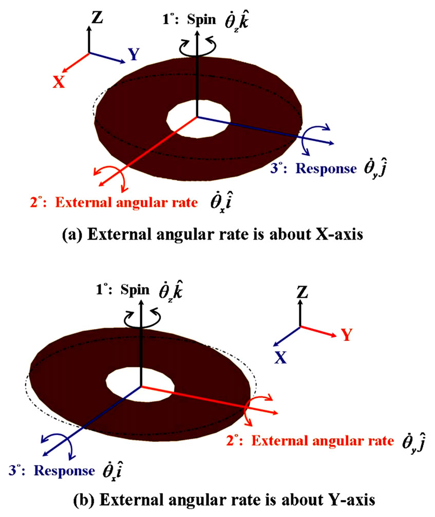
Figure 1. Response of micro-gyroscope
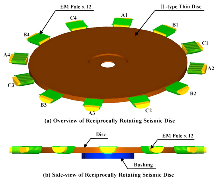
Figure 2. Reciprocally rotating seismic disc
EM poles. In other words, a rotational and alternating magnetic field is constructed by the drive circuit (to be discussed later) to enclose the seismic disc. According to Faraday theorem, two EMFs (Electro-magnetic Forces) are induced between EM poles and the disc made of aluminum. The first kind of EMF is “Motional EMF (![]() )”, which generates the tangential attractive force,
)”, which generates the tangential attractive force,  , on the disc. The second kind of EMF is “Transformer EMF (
 )” which generates the radial repulsive force,
  , on the disc. The tangential force
  makes the disc to rotate but the radial force
  results in further offset and precession of the disc. Since
  and
and  are the main exerted forces applying on the seismic disc, they will be numerically evaluated and addressed in next section. In order to account for the offset and precession of the seismic disc due to the radial repulsive force
  and the inherent mass eccentricity, a control strategy for anticollision on the rotating disc against the centre bearing and the EM poles is proposed and verified in Section 4 and Section 5 respectively.
3. In-Plane Dynamic Model of Disc Position Deviation
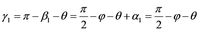
Due to imperfect fabrication (e.g., non-uniform thickness) and the asymmetry of mass distribution, the offset of mass center of the rotating disc with respect to the geometric center (i.e., eccentricity) is definitely inevitable in practice. More over, the position of disc in motion is dynamical and tends to cause collision against the adjacent electro-magnetic poles or the centre bearing. In other words, a control loop is necessary to prevent any potential “overshoot” of the position deviation of the rotating disc. For controller synthesis and computer simulation of the disc dynamics, the in-plane mathematic dynamic model is developed at first in this section. The coordinate system of the rotating disc is depicted in Figure 3, where  is the Inertia Frame and “
 ” the origin. “
 ” is the mass center of disc. “
![]() ” is the geometric center of disc. “
” is the geometric center of disc. “![]() ” is the eccentric distance. “
” is the eccentric distance. “ ” is the position deviation of the mass center. The major modes of the rotation of disc include spin (i.e.,
 ) and precession (i.e.,
 ). It is noted that the spin motion does not cause collision between the disc and the centre bearing at all. Another planar coordinate,
  , is thus defined to describe the linear translation and precession of the disc. By Lagrange’s equation and assumptions:
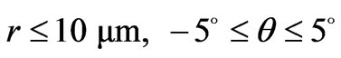 , (the disc is driven to reciprocally rotate within the angular interval,
 ) and
) and  (i.e., 1% of the radius of disc, which is about
 ), the in-plane dynamic model of the rotating disc can be accordingly simplified and established:
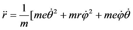
 (1)
(1)
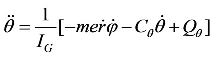 (2)
(2)

Figure 3. Deviation, coordinates and offset of disc
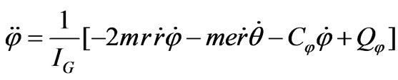 (3)
(3)
where the drive force ( ) and drive moments (
 and
and ) are induced by the electromagnetic poles which enclose the disc. Define
  and
and 
 as the tangential and radial forces generated by the four triplets of 3-phase AC-drive electromagnetic poles. The FBD (Free Body Diagram) of the disc is shown in Figure 4. The geometric relation among
 ,
,  ,
,  ,
, ![]() and
and  is shown in Figure 5, where
 ,
,  ,
,  and
and  are defined as follows:

 (4)
(4)
 (5)
(5)
Since  and
and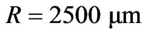 , it leads to
 (6)
(6)
That is,  ,
,
 (7)
(7)
and
 ,
,
 (8)
(8)
The tangential force  can be expressed in terms of
Figure 4. Free body diagram of disc
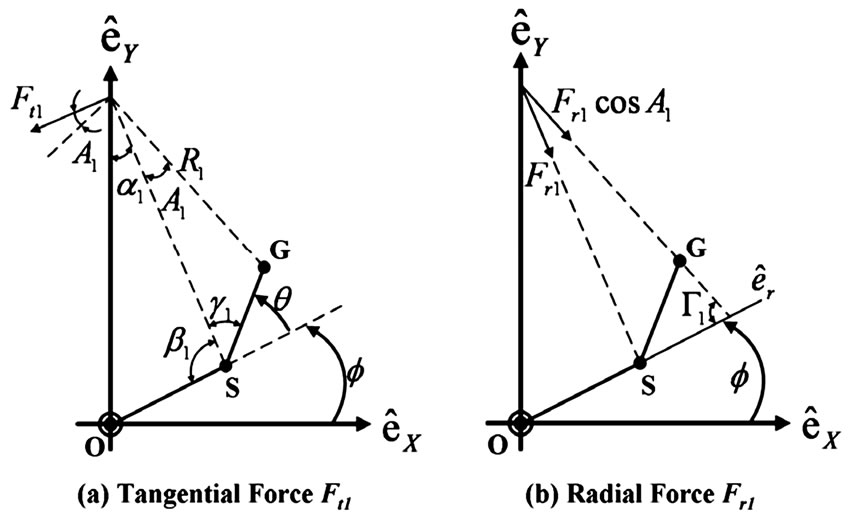
Figure 5. Geometric relation of tangential force Ft1 and radial force Fr1
the drive current frequency, ![]() , and the position of the disc,
, and the position of the disc,  , as follows:
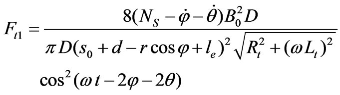 (9)
(9)
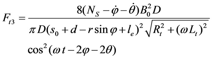
Similarly,
 (10)
(10)
 (11)
(11)
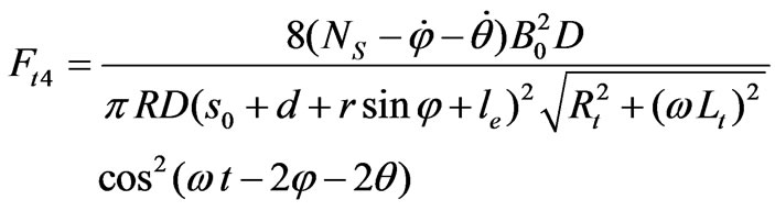 (12)
(12)
By the same arguments, the radial magnetic attractive forces can be evaluated by:
 (13)
(13)
 (14)
(14)
 (15)
(15)
 (16)
(16)
Finally, the drive force ( ) and drive moments (
 and
and ) can be described by:
 (17)
(17)
 (18)
(18)
 (19)
(19)
Based on the dynamic model of the rotation disc, i.e., Equations (1-3) and Equations (17-19), the computer simulations on the disc motion can be undertaken and the control strategies can be therefore developed. They will be addressed in next section.
4. Control Strategy
The control goal of our work is to prevent the rotating disc from collision against the centre bearing so that the electromagnetic poles enclosing the disc can be thus protected. The associate system parameters and their actual values to synthesize the anti-collision controller are listed in Table 1. It is noted that the nominal gap between the disc and the centre bearing cannot be narrowed down much because, as mentioned in Section 2, the disc has to conduct 3-dimensional rotation concurrently.
At first, the open-loop motion of the disc is studied. Once the twelve electromagnetic poles are in-shift energized (i.e., 4 triplets individually and orderly driven by a set of 3-![]() AC drive current), the offset of the geometric center, with respect to time, is shown in Figure 6 with absence of any anti-collision controller. Since the nominal gap between disc and the centre bearing is
AC drive current), the offset of the geometric center, with respect to time, is shown in Figure 6 with absence of any anti-collision controller. Since the nominal gap between disc and the centre bearing is , the disc tends to collide with the centre bearing “immediately”. Let the rotation speed of disc be “n” (in RPM) and the initial angle,
  , defined by
 ,
, . Apparently, the collision between disc and the centre bearing would definitely occur, from Figure 7 and Figure 8, if any anti-collision control strategy is not engaged at all.
As a matter of fact, the disc offset,  , which can be measured and obtained by self-sensing technique [16], can be used as the feedback of control loop to prevent collision. That is, once the disc offset,
  , grows up to a certain level, then a control strategy has to be activated, e.g., shut-down of the supplied current at the EM pole triplet which the disc is approaching. In our work, two LUTs (Look-up Tables) are therefore constructed for the operation for the applied currents at EM poles to be undertaken. In this paper, 4 sense coils (see Figure 9) are selected to carry high-frequency sinusoidal currents (i.e., measurement current) so that the actuation current (in low-frequency) to EM poles is not affected at all. The

Table 1. Physical values of rotating disc and EM poles
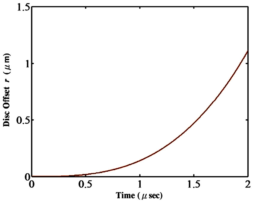
Figure 6. Offset of the geometric center of disc W/O control loop
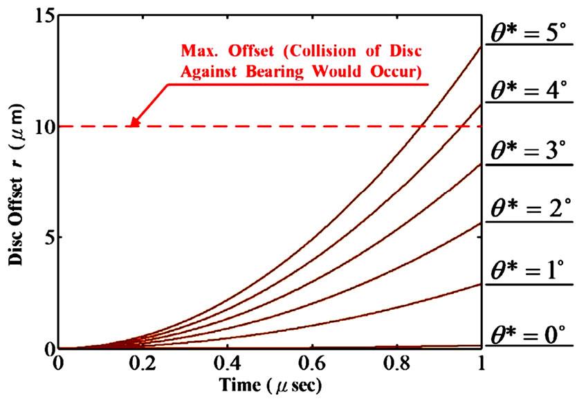
Figure 7. Collision between disc and centre bearing under various initial angles
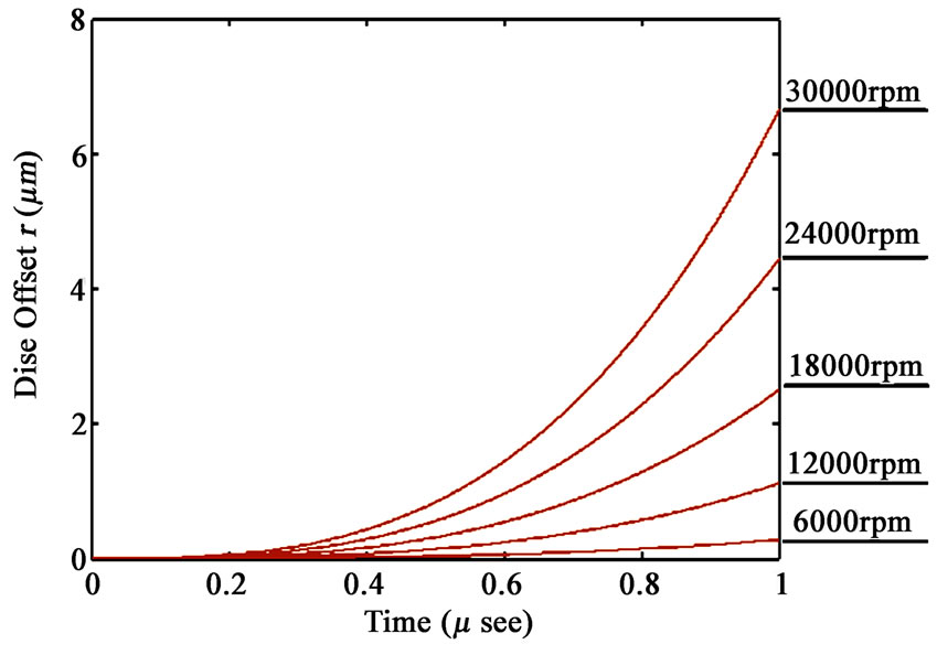
Figure 8. Collision between disc and centre bearing under various spin speeds ( 0*= θ )
self-sensing technique can be referred to our previous work in [16]. For simplicity, denote the EM poles, (A1, B1, C1), as Triplet #1, as shown in Figure 9. Similarly, denote (A2, B2, C2), (A3, B3, C3) and (A4, B4, C4) as Triplet #2, Triplet #3 and Triplet #4 respectively. For each triplet, the pole-to-pole phase shift is  The supplied current to the 4 triplets are:
 ,
,  ,
,  and
and  orderly, where
![]() ,
,  ,
,  and
and  are defined as follows:
 (20)
(20)
 (21)
(21)
 (22)
(22)
 (23)
(23)
 ,
,  ,
,  and
and  are the weights on applied currents and listed in Table 2, referred to as LUT1 (Look-up Table #1).
  is also a weighting factor, whose physical values for various conditions are listed in Table 3, referred to as LUT2 (Look-up Table 2). LUT1 is constructed, on the basis of precession angle and the disc offset,
 . On the contrary, LUT2 is constructed, on the basis of measured spinning speed,
  , and initial spin angle,
 . It is noted that the Interpolation and Extrapolation approaches are employed to calculate
 ,
,  ,
,  ,
,  and
and  for real-time measurements and estimation on (
 ,
, ![]() ,
,  and
and ).
).
An illustrative example is shown in Figure 10. The initial conditions are: offset , initial angle of the mass center,
  and the spinning speed,
 . It is observed that the overshoot of the disc offset is about 6% but successfully suppressed within
 . That is, the rotating disc can be controlled to move within a circular region which allows about
  offset for maximum. On the other hand, the collision between disc and the centre bearing or disc and electromagnetic poles is completely prevented.
5. Drive Circuit for Electromagnetic Poles
The goal of the drive circuit is to make the disc be able to reciprocally rotate within  clockwise and counterclockwise smoothly and switch direction at high-frequency. The drive frequency of the circuit is expected to be identical to the natural frequency of the drive mode of the micro-gyroscope so that expected resonance can be ensured. Normally, it is about
  or above. The drive circuit is composed of 3 portions: power supply module, inverter and the sequential drive control by the MPU (Micro-Processer Unit), shown in Figure 11. The power supply module mainly consists of the rectifierLPF (Low Pass Filter) and the voltage regulator in which differential operation amplifier, OP1, is embedded. The output of the power supply module is a DC voltage which is the input of the inverter, as shown in Figure 12.
This voltage can be evaluated by:
 (24)
(24)
where  is the DC voltage after rectifier in the 3-
![]() AC power supply module.
AC power supply module.  and
and  are the bias resistances of operation amplifier, OP1.
  is variable and controlled by the MPU to tune the magnitude of
 .
.  is the partial resistance of
 .
.
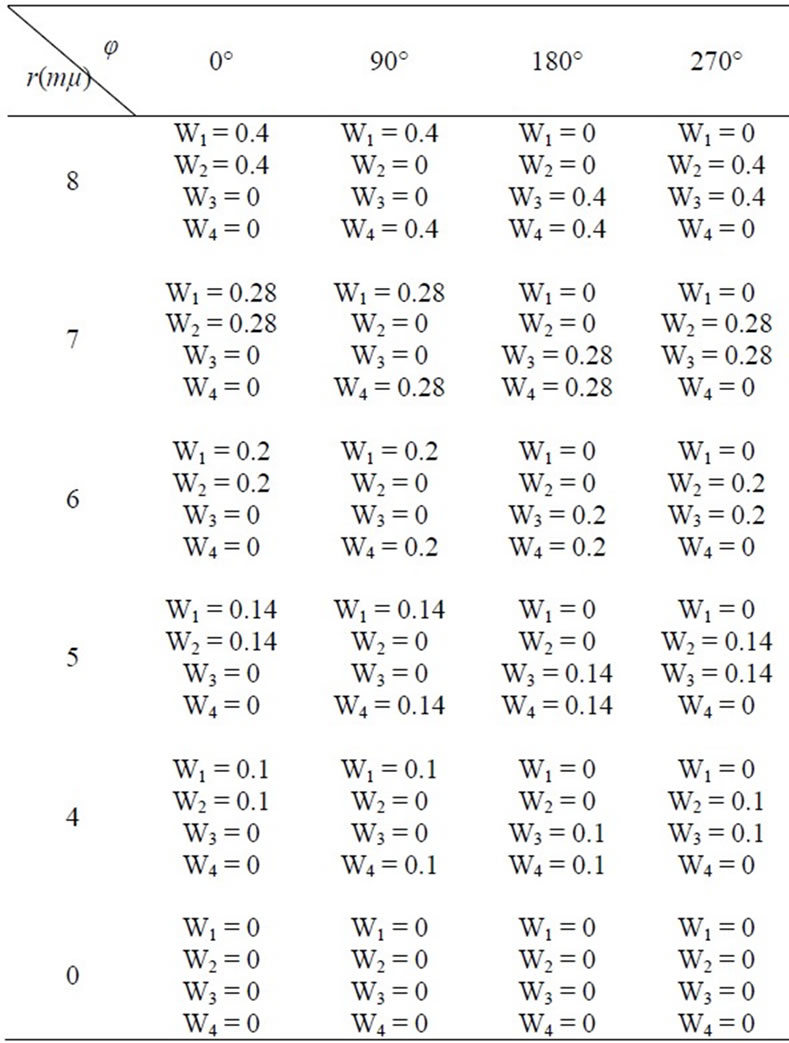
Table 2. Weights of anti-collision controller based on precession angle and disc offset (LUT 1)
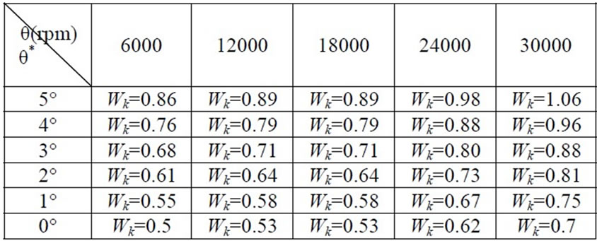
Table 3. Weights of Anti-collision Controller Based on Spin Speed and Initial Spin Angle (LUT 2)
The role of Inverter module, shown in Figure 13(a), is to generate SPWM (Sinusoidal Pulse Width Modulation) signals, in cooperation with MPU which provides the command signal. The six MOSFETs, S1~S6, are sequentially switched on/off by the Inverter module. In order to
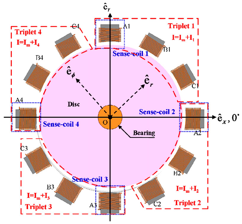
Figure 9. Allocation of the sense-coils, EM poles and supplied currents

Figure 10. Comparison of disc offset for open-loop and closed-loop operations
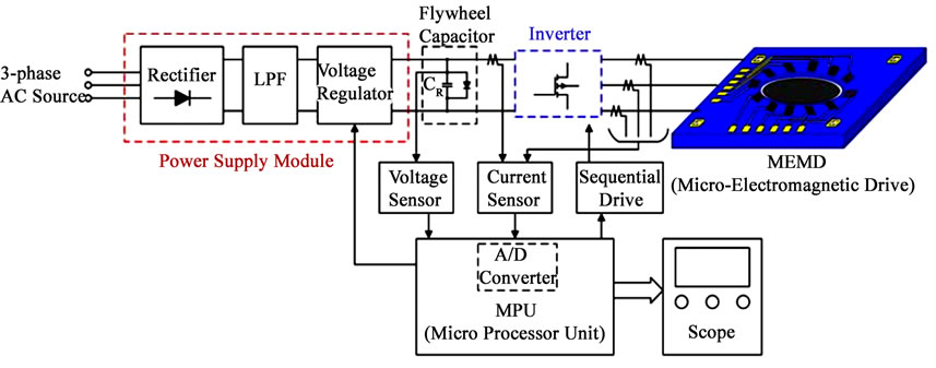
Figure 11. Overview of the proposed drive circuit
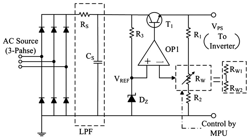
Figure 12. Power supply module
protect MOSFETs from back current, a feedback diode and a set of snubber circuit, show in Figure 13(b), are included.  and
and  denote the magnitude and frequency of the triangle voltage respectively.
 ,
,  and
and  are the applied voltages on Poles A, B and C respectively, with respect to the neutral common “
 ”, as shown in Figure 13. The phase lag between any two adjacent poles is always retained to be
  It is also noticed that the drive frequency and the direction of disc rotation are both controlled by MPU since it can control the order and timing of MOSFETs to be switched on.
Before implementation of the drive circuit, the commercial software, OrCAD 9, is employed to verify the function of the proposed circuit. The resulted voltage output generated by the proposed drive circuit is shown in Figure 14. It is observed that the applied voltages at each triplet of electromagnetic poles are really of sinusoidal waves which are pretty smooth and all pole-to-pole delay is in phase shift,  , orderly.
6. Experimental Results
The actual drive circuit is practically completed and verified under the interface environment constructed by dSPACE DS1104 and MATLAB simulink. The successfully fabricated electromagnetic poles are shown in Figure 15. To examine the efficacy of the control strategy, a test rig, shown in Figure 16, is set up. The control command is provided by MPU for signal trigger. On the other hand, the 3-phase AC power source with peak-topeak  is generated by the power supply module, whose photo is shown in Figure 17(a). The photo of inverter module is shown in Figure 17(b). The test points, TP1, TP2 and TP3, are inspected by the scope and shown in Figure 18 and Figure 19. From Figure 18 and Figure 19, the potential noise is almost suppressed by the aforesaid LPF in last section. Therefore, the expected motion of the disk can be ensured even if any disturbance or noise is present. From Figure 19, it can be verified that the output voltage of the drive circuit, i.e., the drain

Figure 13. Inverter module of the SPWM
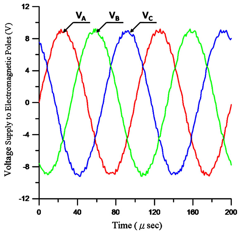
Figure 14. Voltage output generated by the drive circuit

Figure 15. Optical microscope (OM) image of electromagnetic poles
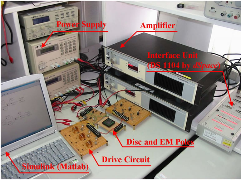
Figure 16. Test rig to examine anti-collision strategy
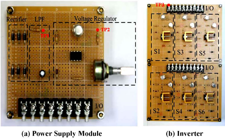
Figure 17. Photo of partial drive circuit

Figure 18. Voltage of test points TP1 (CH1) and TP2 (CH2)

Figure 19. Command voltage at S1 (CH2) and drain voltage VD (CH1)
voltage of the MOSFET, can be successfully controlled by the given command at S1. This implies that the stability and spinning rate of the disk can be considerably assured. Based on the experimental results, the control force and moment, provided by the electromagnetic poles, can be precisely implemented by the proposed control strategy.
7. Conclusions
An innovative drive circuit, in cooperation with a MSU (Micro-Processor Unit), is proposed and verified by experiments to efficiently generate adequate drive power to make the seismic disc oscillate under SPWM (Sinusoidal Pulse Width Modulation) operation. On the other hand, the rotating disc is designed to concurrently conduct three modes of motion: spinning, precession and translation (i.e., offset). That is, the position deviation of the disc has to be regulated or the collision between disc and the centre bearing would occur. An anti-collision controller based on two LUTs (Look-up Tables) to tune the amplitude of applied current to the EMs (Electromagnetic Poles) is presented and examined. On the actuation aspect, the efficacy of drive manner by VVVF (Variable Voltage Variable Frequency) is verified by both computer simulations and experiments. For the sensor aspect, two orthogonal pairs of EM pairs are used as the disc position measurement units. That is, the self-sensing technique has been employed in this work.
Though the drive power by the proposed drive circuit is sufficient to make the disc rotate at high frequency, the sensitivity of frequency mismatch (i.e., the impact on desired resonance) should also be evaluated. The anticollision strategy is, as a matter of fact, to reduce the amplitude of supplied current to the EM poles as the position deviation of disc exceeds the preset upper limit. This implies that the amplitude of the effect of resonance is reduced as well and hence the performance (e.g., resolution) is, to some extent, degraded. These two issues will be investigated in the near future.
8. Acknowledgements
The authors would like to thank the Center for Micro/ Nano Technology Research, National Cheng Kung University, Tainan City, Taiwan, and National Nano Devices Laboratory (NDL 98-C02M3P-107) for equipment access and technical support. This research was partially supported by National Science Council (Taiwan) with Grant NSC 98-2221-E-006-184-MY3 and 99-2622-E- 006-010-CC2.
REFERENCES
- P. Greiff, B. Boxenhom, T. King and L. Niles, “Silicon Monolithic Micromechanical Gyroscope,” in: Proceedings of Technical Digest 6th International Conference Transducers’91, San Francisco, 1991, pp. 966-968.
- S. Lee, S. Park, J. Kim and D. Cho, “Surface/Bulk Micromachined Single-Crystalline-Silicon Micro-Gyroscope,” Journal of Microelectromechanical Systems, Vol. 9, No. 4, 2000, pp. 557-567.
- A. Shkel, R. T. Howe and R. Horowitz, “Modeling and Simulation of Micromachined Gyroscopes in the Presence of Imperfections,” in: Proceedings of International Conference on Modeling and Simulation of Microsystems, Pasadena, 1999, pp. 605-608.
- S. Park, D. Kwak, H. Ko and T. Song, “Selective Silicon-on-Insulator (SOI) Implant: A New Micromachining Method without Footing and Residual Stress,” Journal of Micromechanics and Microengineering, Vol. 15, No. 9, 2005, pp. 1607-1613.
- T. Sarros, E. C. Chew, S. Crase, B. K. Tay and W. L. Soong, “Investigation of Cylindrical and Conical Electrostatic Wobble Micromotors,” Microelectronics Journal, Vol. 33, No. 1-2, 2002, pp. 129-140.
- T. C. Neugebauer, D. J. Perreault, J. H. Lang and C. Livermore, “A Six-Phase Multilevel Inverter for MEMS Electrostatic Induction Micromotors,” IEEE Transactions on Circuits and Systems—II: Express Briefs, Vol. 51, 2004, pp. 49-56.
- N.-C. Tsai, J.-S. Liou, C.-C. Lin and T. Li, “Analysis and Fabrication of Reciprocal Motors Applied for Micro-Gyroscopes,” Journal of Micro/Nanolithography, MEMS, and MOEMS, Vol. 8, No. 4, 2009, p. 043046.
- A. Endemaño, J. Y. Fourniols, H. Camon, A. Marchese, S. Muratet, F. Bony, M. Dunnigan, M. P. Y. Desmulliez and G. Overton, “VHDL-AMS Modelling and Simulation of a Planar Electrostatic Micromotor,” Journal of Micromechanics and Microengineering, Vol. 13, No. 5, 2003, pp. 580-590.
- Y. Lefèvre, M. L. Mazenc, E. Sarraute and H. Camon, “First Steps towards Design, Simulation, Modelling and Fabrication of Electrostatic Micromotors,” Sensor and Actuator A: Physical, Vol. 47, No. 1, 1995, pp. 645-648.
- C. Yang, X. Zhao, G. Ding, C. Zhang and B. Cai, “An Axial Flux Electromagnetic Micromotor,” Journal of Micromechanics and Microengineering, Vol. 11, No. 2, 2001, pp. 113-117.
- Y. Suzuki, K. Tani and T. Sakuhara, “Development of a New Type Piezoelectric Micromotor,” Sensor and Actuator A: Physical, Vol. 83, No. 1, 2000, pp. 244-248.
- J. Tong, T. Cui, P. Shao and L. Wang, “Piezoelectric Micromotor Based on the Structure of Serial Bending Arms,” IEEE Transactions on Iicihasonics, Ferroelectrics, and Frequexcy Control, Vol. 50, 2003, pp. 1100-1104.
- W. C. Wong, X. Zhang, S. A. Jacobson and A. H. Epstein, “A Self-Acting Gas Thrust Bearing for High-Speed Microrotors,” Journal of Microelectromechanical Systems, Vol. 13, No. 2, 2004, pp. 158-164.
- W. M. Zhang, G. Meng, J. B. Zhou and J. Y. Chen, “Slip Model for the Ultra-thin Gas-lubricated Slider Bearings of an Electrostatic Micromotor in MEMS,” Microsystem Technologies, Vol. 45, No. 9-11, 2005, pp. 1230-1242.
- N. Ghalichechian, A. Modafe, M. I. Beyaz and R. Ghodssi, “Design, Fabrication, and Characterization of a Rotary Micromotor Supported on Microball Bearings,” Journal of Microelectromechanical Systems, Vol. 136, No. 2, 2007, pp. 496-503.
- N.-C. Tsai, C.-W. Chiang and H.-Y. Li, “Innovative Active Magnetic Bearing Design to Reduce Cost and Energy Consumption,” Electromagnetics, Vol. 29, No. 5, 2009, pp. 406-420.