Journal of Electromagnetic Analysis and Applications
Vol. 2 No. 4 (2010) , Article ID: 1677 , 6 pages DOI:10.4236/jemaa.2010.24031
Study on Axial Flux Hysteresis Motors Considering Airgap Variation
![]()
Electrical Engineering Department Iran University of Science and Technology, Centre of Excellence for Power Systems Automation and Operation, Tehran, Iran.
Email: mohamamdmodarees@ieee.org
Received November 24th, 2009; revised January 12th, 2010; accepted January 18th, 2010.
Keywords: Hysteresis Loop, Axial Flux Hysteresis Motor, 3D-FEM Model, Complex Permeability, Air Gap Effect
ABSTRACT
Axial flux hysteresis motor (AFHM) is self-starting synchronous motor that uses the hysteresis characteristics of magnetic materials. It is known that the magnetic characteristics of hysteresis motor could be easily affected by air gap and structure dimensions variation. Air gap length plays an important role in flux distribution in hysteresis ring and influences the output torque, terminal current, efficiency and even optimal value of other structural parameters of AFHM. Regarding this issue, in this study effect of air gap variation on performance characteristics of an axial flux hysteresis motor and effect of air gap length on hysteresis ring thickness and stator winding turns is investigated. Effect of air gap length on electrical circuit model is perused. Finally, simulation of AFHM in order to extract the output values of motor and sensitivity analysis on air gap variation is done using 3D-Finite Element Model. Hysteresis loop in the shape of an inclined ellipse is adopted. This study can help designers in design approach of such motors.
1. Introduction
The main features of hysteresis motor are Simple construction with conventional three phase stator windings, solid rotor ring and constant self-starting torque during the run-up and synchronization period [1]. These advantages make the hysteresis motor especially suitable for applications, such as compressors, pumps, timing and recording equipment [2]. Hysteresis motors use the hysteresis characteristics of magnetic materials. It is known the magnetic characteristics of the motor could be easily affected by air gap length and structure dimensions variations [3-5]. Regarding this issue, in this study effect of air gap variation on performance characteristics and optimal hysteresis ring thickness and stator coil turns of axial flux hysteresis motors is investigated. Effect of airgap length on electrical circuit model is perused. Meanwhile, the finite element method (FEM) is implemented for accurate simulation. Such simulation is based upon Maxwell’s field equations considering the case of a circumferential flux type machine at synchronous speed. A hysteresis loop in the shape of inclined ellipse is adopted. Also, the application of complex permeability concept is implemented in order to model the hysteresis loop. In this study a 3D finite element model is implemented in order to simulate AFHM. This 3D model has high level of accuracy and gives us a better insight of motor performance. All in all, the objective of this paper is to derive the performance characteristics of axial flux hysteresis motor and to perform sensitivity analysis of such motors at synchronous speed based on 3D FEM. Also, this model can be used in the design approach and precise analysis of axial flux hysteresis motors.
2. Structure and Winding Configuration
This type of motors do not have slot on their rotors and the rotor structure is quite simple. Hysteresis ring is made up of semi hard magnetic materials that can conduct flux line circumferentially. The schematic structure diagram of a two pole axial flux hysteresis motor without ring holder is shown in Figure 1. As seen in diagram, the upper surface of the stator has tooth and slots. This stator has a unique three-phase winding that lead to small resistance and the rotor of such motors is generally designed as a disc type motor. The rotor is made up of two parts. Firstly, hysteresis ring which is the basic element for the torque providing that is made of semi hard magnetic material. Secondly, the hysteresis ring holder; which almost is made of the nonmagnetic material such as aluminum and its alloys. This part of motor does not have any effect on steady state operation mode of motor and only is a copulative between the rotor and the motor shaft. These parts of motor are shown separately in Figure 2.
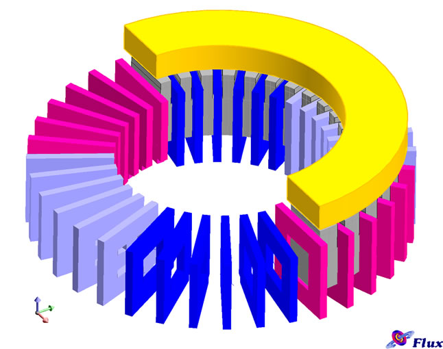
The winding diagram and terminal connection mode of the 2-pole stator windings is shown in Figure 3.
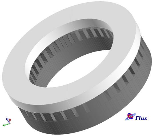
Figure 1. The schematic structure diagram of an axial flux hysteresis motor without ring holder
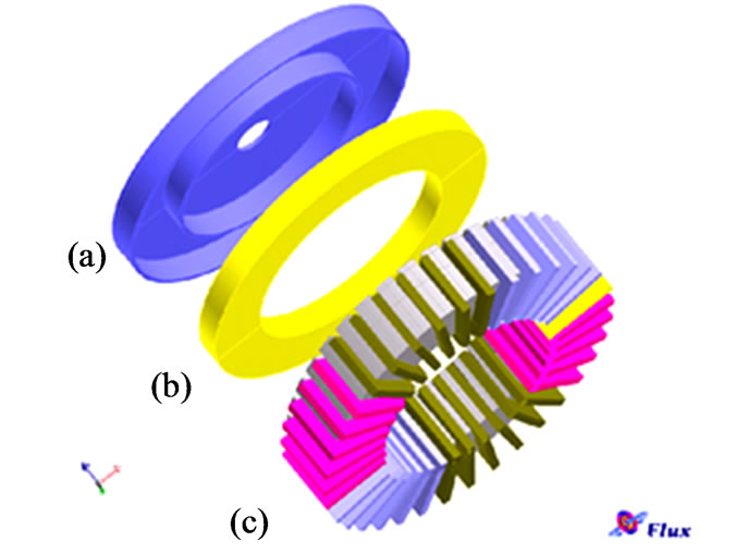
Figure 2. Different parts of axial flux hysteresis motor. (1) Holder; (2) Hysteresis ring; (3) Stator and winding
 (a)
(a)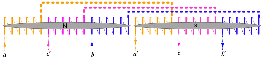 (b)
(b)
Figure 3. (a) Winding diagram; (b) Stator terminal connection of 2-pole hysteresis motor
3. Air Gap Effect on Electrical Circuit
Figure 4 shows the equivalent electrical circuit of axial flux hysteresis motor [4].
It is proved that air gap length has effect on stator leakage reactance and magnetizing reactance. Equations that show the effect of air-gap on those terms are as bellow [4]:
1-Stator leakage reactance is component of three terms:
 (1)
(1)
where Xslot is the slot reactance, and Xend is the ending reactance.
 is the belt or differential leakage reactance and its value can be determined by the following equation and an iterative method [4]:
 (2)
(2)
In order to specify , firstly the values of Km coefficients should be calculated [4].
 (3)
(3)
where,  is the air gap area of one pole and
  is the effective air gap length.
2-Magnetizing reactance [4]:
 (4)
(4)
In this equation  is air gap inductance that depends on effective air gap length [4].
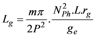 (5)
(5)
So, variation of air gap length has effect on two terms of equivalent electrical circuit and this effect can influence output characteristics of motor. In next parts, the simulation approach of AFHM is presented in order to investigate the air-gap variation effect.
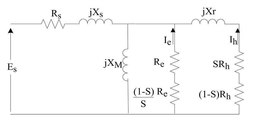
Figure 4. Equivalent electrical circuit of three phase axial flux hysteresis motor
4. Hysteresis Loop Approximation
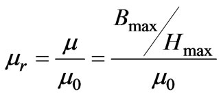
In this study, a complex permeability is used to predict the hysteresis loop in the inclined ellipse shape. There is some papers that deal with complex permeability and its theory [6-8]. The complex permeability is a useful tool for dealing with magnetic effect. In this study, a complex permeability is used to predict the hysteresis loop in the inclined ellipse. Shape Figure 5 helps us to exploit the real and imaginary parts of complex permeability ( and
and ) as a function of Hmax, HC and Bmax [9].
 (6)
(6)
 (7)
(7)
 (8)
(8)
 (9)
(9)
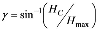
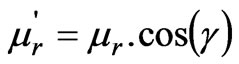
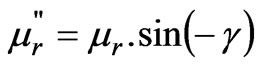
where γ is hysteresis lag angle between flux density and magnetic field intensity,  is the relative permeability,
  and
and  are the real and imaginary part of complex permeability.
As known, for a hysteresis material there is different hysteresis loop. In order to choose an accurate loop regarding to magnetic circuit that hysteresis material is in, an iteration method is used that is illustrated with a flow chart in Figure 6. In the first iteration, a random hysteresis ring is selected. So, all the hysteresis ring elements have the arbitrary permeability. From the FEA, the maximum flux density for the circumferential direction in the hysteresis ring region can be obtained. Now, the maximum flux density obtained from FEA is checked with previous value and this procedure continues until the convergence criterion is satisfied. If the analysis is completed, torque of motor can be evaluated. It is so important to select an accurate hysteresis loop since the output torque of the motor is proportional to the area of hysteresis loop [10,11] regarding Equation (5).
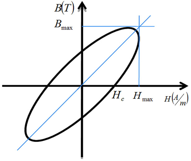
Figure 5. Inclined hysteresis loop approximation
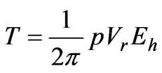 (10)
(10)
where, p is number of pole pairs, Vr is the hysteresis ring volume and Eh is the area of hysteresis loop.
It is seen that that this procedure is so effective and hysteresis loop modeling with complex permeability has close agreement with real motor tests.
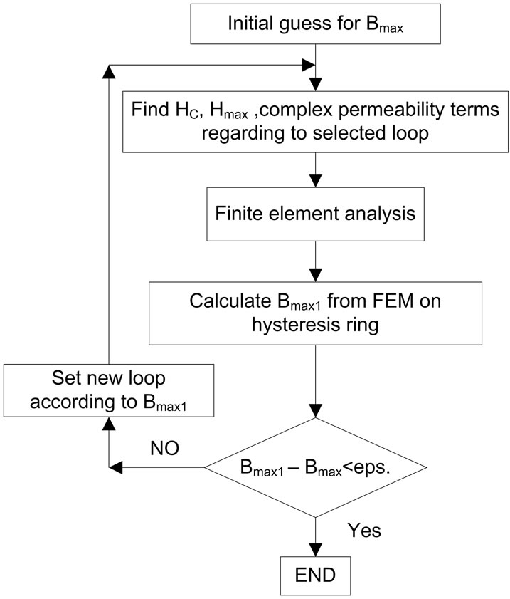
Figure 6. Flow chart for accurate hysteresis selection
5. FEM Model
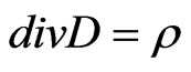
As mentioned before, a 3D finite element model is implemented in order to simulate of proposed motor [12]. This 3D model has high level of accuracy and gives us a better insight of motor performance. Finite element method is based on Maxwell’s equations. The electromagnetic field inside the machine is given by:
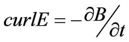 (11)
(11)
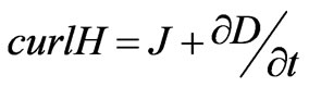 (12)
(12)
 (13)
(13)
 (14)
(14)
In order to have high level of accuracy the automatic mash diagram is not used and a mesh diagram is designed manually. In this simulation node congestion is higher around the air gap and hysteresis ring. Hexagonal element in stator and trigonal prism element is used in rotor in order to constitute the mesh diagram. The total number of nodes is about 130000 that lead to high level of accuracy. Meanwhile, for boundary conditions, the homogenous Dirichlet condition is adopted on the infinite box that encompasses the motor.
This simulation is based on circuit coupled model that the phase voltage is the input quantity. Figure 7 shows the circuit coupled model that is used in this study. In this model for each phase two coil winding is considered. One of this coils send the current in motor and another returns current from midpoint of winding in star connection. Coil winding connection in each phase is exactly as the same that is illustrated in Figure 3(b). Meanwhile, in this model voltage source is assumed as the input source.
6. Simulation Results and Discussion
Based on the above respects, finite element simulation for the axial flux hysteresis motor has been done. The simulation research has been made for a 2 poles prototype AFHM. The parameter of the prototype axial flux hysteresis motor and the output quantities of motor for 2 mm air gap is given in Table 1.
It must be noted that half of the motor is analyzed because of the magnetic symmetry of the motor. As seen in Figure 8 nodes congestion becomes higher near the air gap and hysteresis ring in order to accurate simulation.
Figure 9 shows the distribution of flux in motor.
As said before, flux lines are circumferentially through the hysteresis ring.
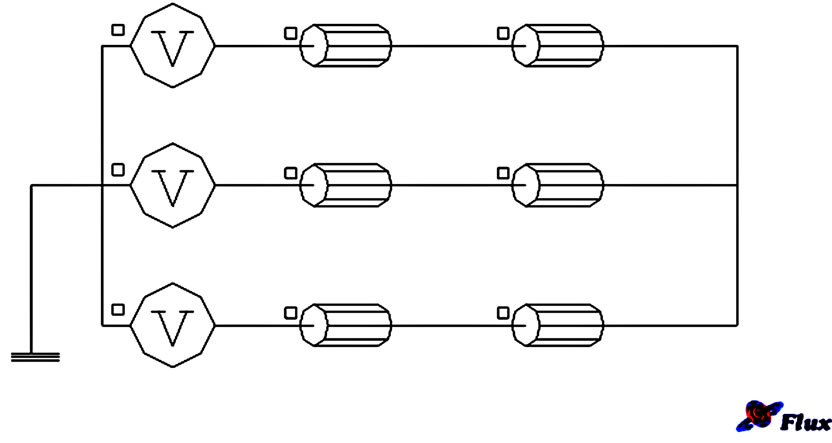
Figure 7. Circuit coupled model used in simulation
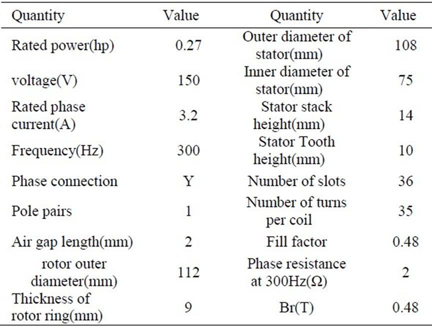
Table 1. Motor characteristics
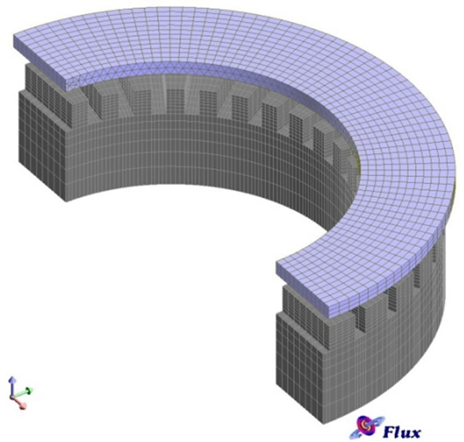
Figure 8. Mesh congestion is higher near air gap and hysteresis ring
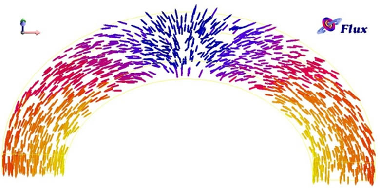
Figure 9. Distribution of the circumferential flux
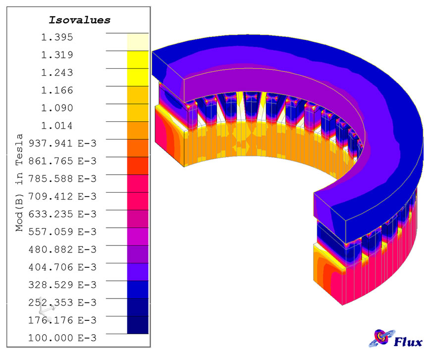
Figure 10. Isovalues diagram of flux density of axial flux hysteresis motor
Figure 10 shows the isovalues diagram of flux density in motor.
Since now based on FEM model the simulation of motor for real dimensions is done and the output characteristics of motor is extracted. Now by change the air gap from 0.6 mm to 4 mm the variation of output quantities is investigated.
Figure 11 demonstrates variations of the input current of the machine versus air gap length of motor.
From Equations (3) and (5) it is obvious that air gap reduction leads to higher value of  and
and . So, impedance has increased and input current has a less value.
The maximum flux density in rotor ring for various air gap is illustrated in Figure 12.
Figure 13 demonstrates variations of the torque of the machine versus air gap length of motor.
As the air gap length reduced, distribution of flux density in air gap has higher value and this effect leads to higher flux density in hysteresis ring. So, the output torque increases.
Figure 14 demonstrates variations of the power factor of the machine versus air gap length of motor.
From this diagram it is found that the relative of real part of impedance to imaginary part is increased by lower air gap length. The magnetizing current is decreased by lower values of airgap and so the imaginary part of current is decreased, too.
Figure 15 demonstrates variations of efficiency of the machine versus air gap length of motor.
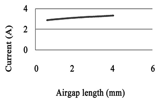
Figure 11. Terminal current variation versus air gap length
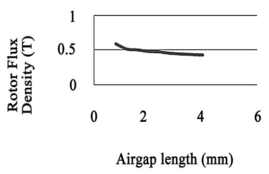
Figure 12. Maximum flux density in rotor versus air gap length
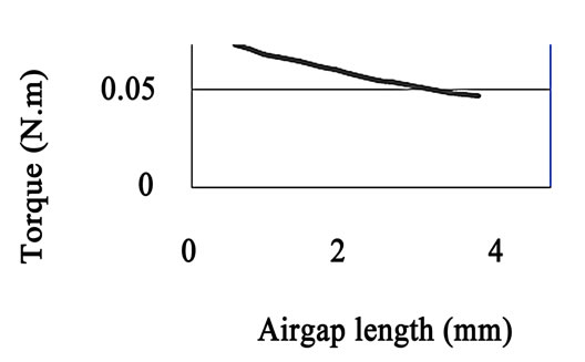
Figure 13. Output torque variation versus air gap length
By reduce in air gap length input power is reduced by lower level of input current and the output torque is increased, so it is obvious that the efficiency will be increased.
Figure 16 demonstrates variations of the hysteresis ring thickness versus air gap length of motor under constant load.
According to Figure 12 it can be extracted that the lower air gap length lead to higher maximum flux density on hysteresis ring and higher flux density lead to bigger hysteresis loop. So area of hysteresis loop increases with lower air gap length. Meantime, Equation (10) shows for constant load torque the bigger hysteresis loop area lead to smaller hysteresis ring volume. Thus, when the air gap length is decreased, the thickness of hysteresis ring is decreased, too. Though, simulation shows that for air gaps bigger than 3.2 mm, thicker hysteresis ring cannot produce base torque and the hysteresis ring is in saturated zone.
Figure 17 demonstrates variations of the stator winding turns versus air gap length of motor under constant load.
According to Figure 11 it can be extracted that the lower air gap length lead to lower terminal current and lower terminal current lead to lower ampere-turn. So, for
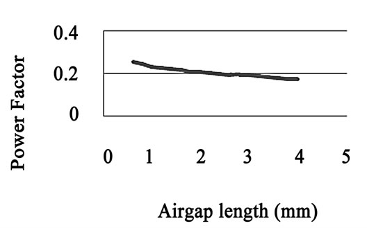
Figure 14. Power factor variation versus air gap length

Figure 15. Efficiency variation versus air gap length
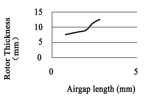
Figure 16. Hysteresis ring thickness versus air gap length
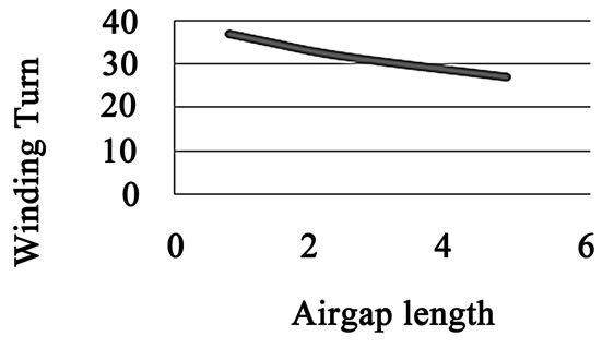
Figure 17. Stator winding turns versus air gap length
constant load number of stator turns must be increased to produce same ampere-turns.
7. Conclusions
In this paper, for an accurate analysis of the hysteresis motor and to perform the sensitivity analysis for axial flux hysteresis motor a finite element analysis model is used. A hysteresis loop in an inclined ellipse shape is adopted to approximate the hysteresis loop. Therefore, the method can consider the rotational hysteresis effects which the scalar hysteresis model cannot deal with. The simulation based on real dimensions of a typical motor is done. Effect of air gap variation on output quantities of such motors, and optimal thickness of hysteresis ring and stator winding turns under constant load is investigated. Furthermore all simulation results show that smaller air gap (g) how much increases machine efficiency, Power factor, maximum flux density, torque and stator winding turns and reduces the terminal current and hysteresis ring thickness for constant load. So by considering the mechanical constrains, the air gap is assumed minimum possible value.
REFERENCES
- M. Azizur Rahman, “Analytical Models for Polyphase Hysteresis Motor,” Rotating Machinery Committee of the IEEE Power Engineering Society, December 10, 1970.
- M. Azizur Rahman and R. F. Qin, “Starting and Synchronization of Permanent Magnet Hysteresis Motors,” IEEE Transactions on Industry Applications, Vol. 32, No. 5, September/October 1996.
- K. R. Rajagopal, “Design of a Compact Hysteresis Motor Used in a Gyroscope,” IEEE Transactions on Magnetic, Vol. 39, No. 5, September 2003.
- A. Darabi, H. Lesani, T. Ghanbari1 and A. Akhavanhejazi, “Modeling and Optimum Design of Disk-Type Hysteresis Motors,” Proceeding of International Conference on Electrical Machines and Systems, 8-11 October 2007, Seoul, Korea.
- A. Sedagati and A. Vahedi, “Effect of Parameters Design on the Characteristics of Hysteresis Motor,” IEEE Conference, Electrical Machines and Systems, Vol. 1, 9-11 November 2003, pp. 246-249.
- F. A. A. Zaher, “An Analytical Solution for the Field of a Hysteresis Motor Based on Complex Permeability,” IEEE Transaction on Energy Conversion, Vol. 5, No. 1, March 1990.
- M. Modarres, A. Vahedi and M. R. Ghazanchaei, “New Topology of a Slotted Disk Type Hysteresis Motor,” Proceedings of International Conference on Coil Winding, Insulations & Electrical Manufacturing (CWIEME), Mumbai, India, November 2009.
- T. Horii, N. Yuge and G. Wakui, “Analysis of a Hysteresis Motor on Asynchronous Speed Using Complex Permeability,” IEEE Translation Journal on Magnetics in Japan, Vol. 9, No. 2, March/April 1994.
- M. Getzlaff, “Fundamental of Magnetism,” SpringerVerlag, Berlin, 2008.
- H. K. Kim, S. K. Hong and H. K. Jung, “Analysis of Hysteresis Motor Using Finite Element Method and Magnetization-Dependent Model,” IEEE Transactions on Magnetic, Vol. 36, No. 4, July 2000.
- S. K. Hong, H. K. Kim, H. S. Kim and H. K. Jung, “Torque Calculation of Hysteresis Motor Using Vector Hysteresis Model,” IEEE Transactions on Magnetic, Vol. 36, No. 4, July 2000.
- CEDRAT Group, “Flux3D User’s Guide,” Version 10.3, France, 2009.