Journal of Electromagnetic Analysis and Applications
Vol. 1 No. 4 (2009) , Article ID: 1114 , 9 pages DOI:10.4236/jemaa.2009.14033
Optimal Design and Control of a Torque Motor for Machine Tools
![]()
Department of Mechanical Engineering, National Taiwan University, Taipei, Taiwan, China.
Email: {ypyang@, r94522816, jjliu}@ntu.edu.tw
Received July 23rd, 2009; revised August 19th, 2009; accepted August 26th, 2009.
Keywords: Multi-Objective Optimization, Torque Motor, Machine Tool, Optimal Current Waveform
ABSTRACT
This paper presents a systematic approach of optimal design and control of a surface-mount, permanent-magnet synchronous torque motor for the next-generation machine tools. A step-by-step procedure of optimization integrates multiple performance objectives and constraints to help the designer make the best decision on the final motor geometry from both design and control perspectives. In the perspective of design, a torque motor with concentrated windings and similar numbers of slots and poles may achieve the desired performance after optimization for multiple objectives, leading to a sinusoidal flux density for a nearly ripple-free torque distribution. From the control perspective, an optimal current waveform with an ideal shift angle is determined for each phase by aligning the current excitation with the back electromotive force. Both design and control of the surface-mount, permanent magnet machine are verified by the finite element method, and a prototype is fabricated for performance validation.
1. Introduction
In many industrial applications, torque motors attract much attention by their appealing features of high torque density, high efficiency and low ripples. A particular type of permanent magnet (PM) motor uses advanced electronic commutation to replace traditional mechanical commutation. This simple structure makes it easier to fabricate at low cost in the direct or indirect-drive arrangement. The direct-drive arrangement eliminates transmission trains and gearboxes to operate at a lower speed with higher torque in various implementations of machine tools and transportation vehicles. The geometry of assembly of a surface-mount, permanent magnet (SPM) torque motor is illustrated in Figure 1.
To achieve its optimal performance, a torque motor needs a systematic methodology of design and control. From the design perspective, the motor configuration and geometry are determined in an optimal way by maximizing the output torque with minimal weight and least power consumption. First, the configuration of concentrated windings, instead of distributed windings, is determined because of its advantages of short end windings and simple structure. Similar numbers of slots and poles are also selected [1–3], so that the slot pitch is close to the pole pitch, not only to reduce the copper loss but also to produce the largest torque in the concentrated windings. The symmetric winding layout of similar numbers of slots and poles is very suitable for conventional three-phase drives [4]. Second, the motor geometries, such as the shape of the magnet and stator tooth, are crucial parameters for motor performance. Hsieh and Hsu [5] and Islam et al. [6] made several investigations on a motor with sinusoidal current excitations and found that the waveform of magnetic flux was very sensitive to the shape of the magnet. Recently, Yang et al. [7] invented a rim motor of sectional stators and arc magnets; its magnetic flux distribution in the air gap was close to a sinusoidal function, thereby producing a near-sinusoidal back

Figure 1. The SPM machine assembly
electromotive force (EMF) with fewer harmonics.
From the control perspective, it is usually expected to find an optimal current waveform to maximize the output torque and efficiency of a motor under prescribed constraints. Jahns and Soong [8] introduced a control-based technique for minimizing torque ripples by tuning the current waveform with an on-line or off-line controller. Chan et al. [9] and Kim et al. [10] proposed their sensorless drives for high bandwidth torque control by both the back EMF estimation with fundamental excitation and the saliency-based method with carrier frequency excitation. As for the driving patterns, the optimal current waveform to produce a maximum torque is proportional to the magnetic flux variation in the air gap, which shares the same waveform with the back EMF [11].
Among the previous researches, few papers have ever integrated both the design and control perspectives into the motor design. This paper initiates a systematic approach for designing a torque motor to improve its torque capacity and to reduce torque ripples from both the design and control points of view. The flowchart of the proposed design process is presented in Table 1.
2. Specifications
The proposed torque motor will operate for machine tools over a low speed range with high accuracy and resolution, such as the application to a multi-axis highprecision machine center, computer numerical control milling machine or semiconductor handling equipment. A radial-flux SPM motor is chosen as the target sample to satisfy the major specifications in Table 2.
3. Preliminary Design
According to the design specifications, a preliminary model of the SPM motor is proposed in Figure 1, featuring a large diameter-to-axial-length ratio, which provides a thin ring with more space for bearings, sensors and other components in the hollow shaft of the rotor. The outer surface of rotor is embedded with permanent magnets to face their surrounding stator teeth, and the exterior of the stator back iron is enclosed by a water cooling house.
3.1 Basic Motor Configuration
3.1.1 Winding Type
Concentrated windings have simpler structure with shorter end windings than distributed windings, thereby yielding less flux leakage and power loss. It is also possible for the motor of concentrated windings to increase torque production by similar numbers of slots and poles, which also result in significantly low torque ripples [12]. Therefore, concentrated winding is preferred and selected for the torque motor in this paper.
3.1.2 Determination of the Number of Slots and Poles
It has been proved that a motor of fractional slot and pole ratio with concentrated windings may have a high torque density, and a motor of similar numbers of slots and poles will make the torque ripple so low that neither rotor nor stator skewing is necessary. Three useful factors will help a designer determine the number of slots and poles:
1) Number of slots per pole per phase
 (1)
(1)
where Ns is the number of slots, p is the number of pole pairs and Nph is the number of phases. A motor is called fractional when Nspp has a fractional part; when Nspp is less than one and Ns = 2p±2, the motor is said to have

Table 1. Systematic design and control procedure
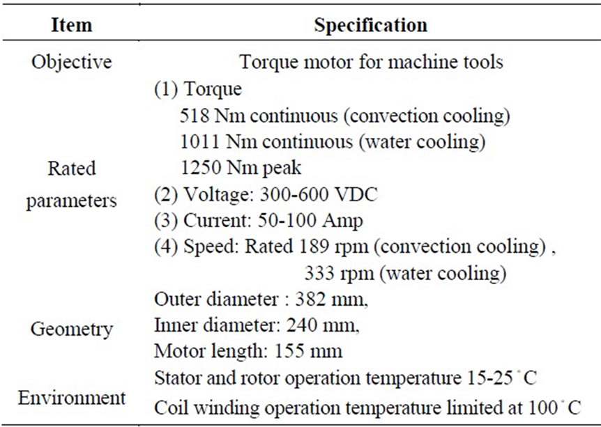
Table 2. Specifications of torque motor
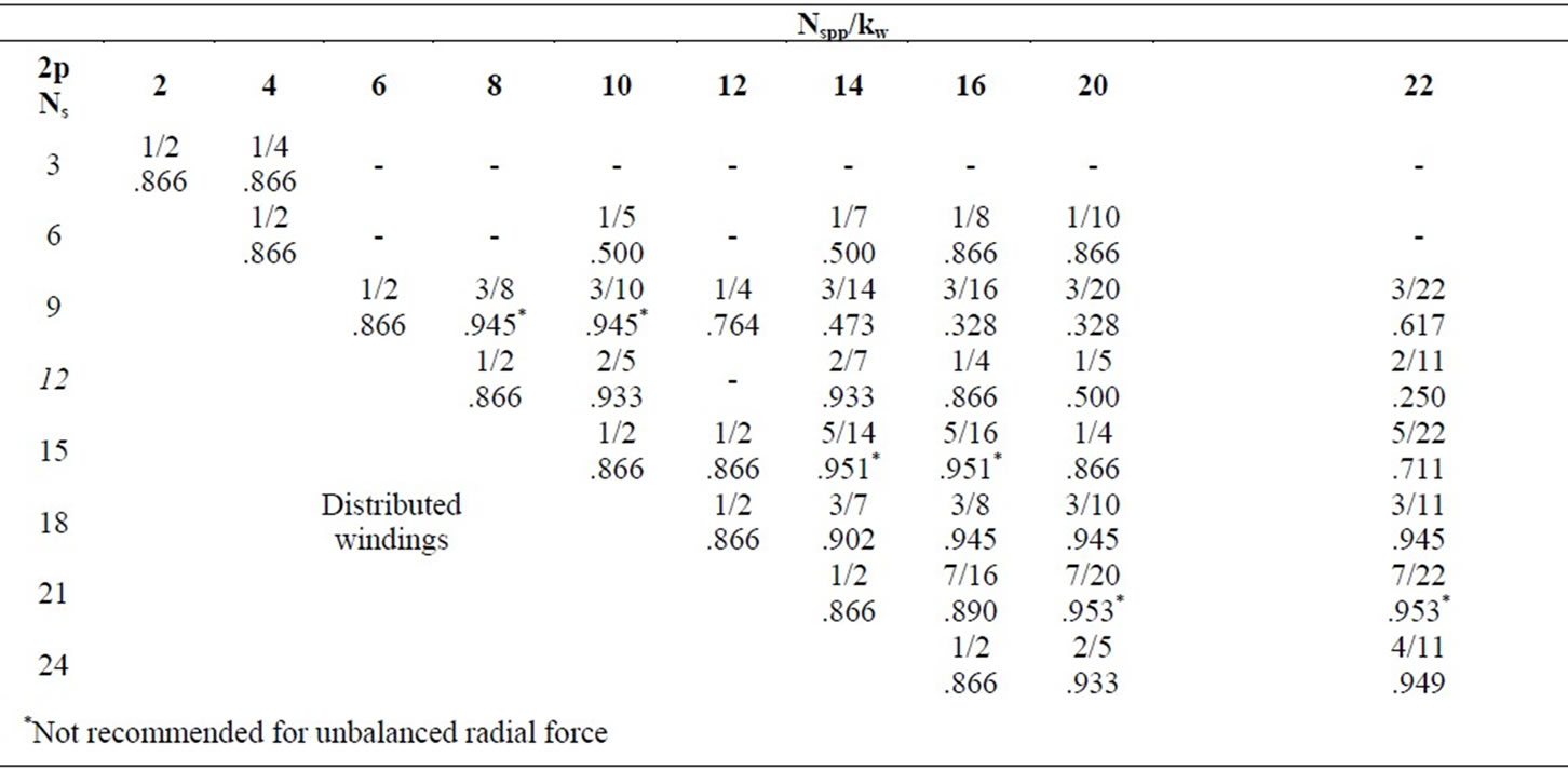
Table 3. Fractional Nspp and winding factor kw for 3-phase motors
similar numbers of slots and poles. Both properties render a motor with fewer torque harmonics, hence fewer ripples.
2) Winding factor kw
The winding factor of concentrated windings is defined as
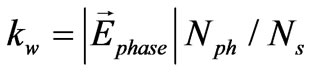 (2)
(2)
where  is the resultant back EMF phasor of a phase formed by its corresponding winding elements. The winding factor is an indication of what portion of the magnet is covered by the stator windings of a single phase.
3) Index factor CT
The index factor CT is defined to evaluate the amplitude of cogging torque for various slot and pole numbers:
CT = 2pNs / Nc (3)
where Nc is the least common multiple of the numbers of poles and slots. In general, a small index factor may indicate small amplitude of cogging torque; its smallest number is 1 when 2p and Ns are relatively prime.
It is convenient to make a table of Nspp and kw for various combinations of slots and poles, among which the promising ones are selected in regard to the index factor, motor size and the performance of torque and torque ripple. Table 3 shows selected slot and pole combinations of fractional Nspp. First, those combinations with similar numbers of slots and poles, balanced windings and greater slot numbers are selected and marked in grey. Then, the largest winding factor 0.949 for the machine of 24 slots and 22 poles, designated the 24/22 machine, or other machines of the same slot and pole ratio, such as the 48/44 machine, becomes one of the candidates for optimal design. Since the specification of diameter in Table 2 allows a large number of slots and poles, the 48/44 machine is selected.
To validate this choice, the performance test was made by comparing it with other arrangements of slots and poles with winding factors of 0.866 and 0.933, which belong to the classes of the slot and pole ratios of 3:2 and 6:5, respectively. Since the diameter specification allows the inclusion of more slots, the machines of 72/48, 60/50 and 48/44 were selected for the performance test in terms of torque and torque ripple, as shown in Table 4.
In this test, all machines were excited with the same magneto-motive force (MMF) from magnets and the same phase current of 50 a from stator windings. The 48/44 machine produced the highest torque among the three machines. Although the torque ripple of the 48/44 machine was a little higher than the 60/50 machine, because of its flux saturating in the stator teeth, it is still the best choice among the three for its largest torque, winding factor and smallest index factor. Being configured of optimal design and finite element refinement will further improve its performance.
3.1.3 Determination of Magnet Shape
The back EMF waveform of SPM motors depends on the shape and pitch of magnet poles and stator teeth. The rectangular magnet is most commonly used because of certain manufacturing and cost advantages. The fan-shaped magnet is an improvement over the rectangular one,

Table 4. Performance test result
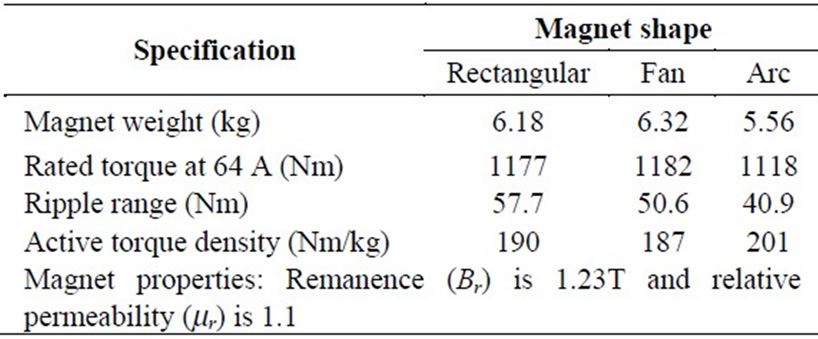
Table 5. Rated specifications for different magnet shapes
 (a)
(a) (b)
(b)
Figure 2. (a) Arc magnet and (b) design variables of stator and rotor of SPM machine
but it may cause manufacturing complexity. The arc magnet is promising for producing a smooth sinusoidal back EMF so as to match the excitation of the sinusoidal current waveform. An ideal arc shape in Figure 2(a) is expressed as a cosine function of magnet pole pitch tm [5] and the air gap length dr on the rotor side can be approximated by
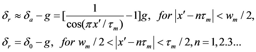 (4)
(4)
where d0 denotes the air gap length between the top of the stator teeth and the bottom of the rotor. The coordinates x and  are the peripheral coordinate fixed on the stator and rotor, respectively, along the circle of the average radius R = (Rsi+Rro)/2, while Rsi is the inner radius of the stator and Rro is the outer radius of the rotor.
Table 5 compares the motor performance for different magnet shapes. The motor with fan magnets provides the maximum rated torque at 64 A, but has a minimum torque density for extra magnet weight. However, the range of ripples, measuring the difference between the upper and lower values of torque ripple, is minimal for the motor with arc magnets. Its active torque density, defined as the ratio between the rated torque and magnet weight, is also maximal among the three. Besides, the back EMF constant produced by the motor with arc magnets is closest to a sinusoidal function, thus providing the lowest torque ripple. The arc magnets, therefore, become the best choice at the preliminary design stage.
3.2. Analytical Magnetic Circuit Model
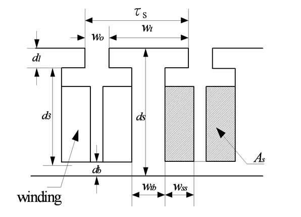
According to the preliminary motor configuration, a 2D analytical magnetic circuit model based on the theory of electromechanical energy conversion is built to describe the performance of the 3D motor in terms of a set of objective functions, such as motor torque, torque density, speed and efficiency. These objectives are expressed as functions of motor geometries, which are illustrated as design variables in Figure 2(b) and are to be determined through the optimization process.
In addition to the assumptions of material linearity and the collinearity of flux and field densities, it is also necessary to make three additional assumptions for the 2D magnetic circuit model:
1) The motor is operated in the linear range of the B-H curve of the magnetic material.
2) The air-gap reluctance of the slotted stator structure is approximated by the effective air-gap length with Carter’s coefficient [13].
3) The flux flows straight across the air gaps between the stator and rotor, ignoring the fringing flux to simplify the analysis.
Therefore, the 3D motor structure in Figure 1 can be approximated by a 2D configuration in Figure 3(a) to facilitate the magnetic circuit analysis. By neglecting the flux leakage and armature reaction between the stator and rotor, the MMF from stator windings Fs is simply a square function of magnitude NtI; while the MMF from rotor magnets Fr is a square function of magnet Hclm, where Hc and lm are the coercivity and length of magnet, respectively. The overall MMF distribution is a linear combination of the MMFs of stator windings and rotor magnets
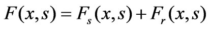 (5)
(5)
where s denotes the rotor shift, which is defined as the relative angle between the rotor and stator.
The magnetic flux density in the air gap is described as
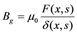 (6)
(6)
where m0 is the permeability of air, d (x,s) is the effective air gap as a function of slot opening and slot pitch, as shown in Figure 3(b). By the use of the detailed expression of effective air gap [13], the field coenergy in the air gap is expressed as
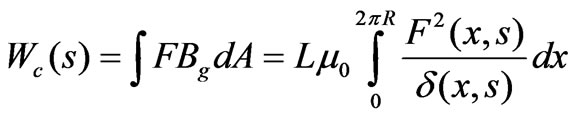 (7)
(7)
where L is the axial length of the motor. The torque produced in the motor is then obtained by calculating the variation of magnetic coenergy in the air gap with respect to the rotor shift:
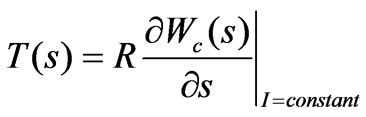 (8)
(8)
It may be possible to express the coenergy and torque in analytical forms. However, the numerical analysis is used instead to get torque distribution from such a complicated magnetic model. Therefore, the coenergy and torque (7) and (8) are rebuilt in the discrete form as
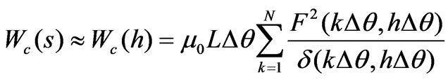 (9)
(9)
 h=1,2,3,…(10)
where each electric period is divided into N equally spaced points, separated with mechanical position  from each other, while
 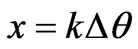 and
and . These discrete equations will be used for the multi-functional optimal design in the next step.
4. Optimal Design
The performance of the torque motor is usually evaluated by its maximum torque, torque density and efficiency, which are also known as objective functions or performance indices, describing the mechanical and electrical dynamics in terms of motor geometries, magnetic materials and driving conditions, as follows:
1) Rated torque max (11)
(11)
2) Torque density

Figure 3. (a) 2-D motor configuration and magneto-motive force, and (b) effective air gap width due to slotting effect
max  (12)
(12)
3) Rated efficiency max  (13)
(13)
Here, the rated torque Tr is an implicit function of design variables, and is calculated through analytical magnetic circuit models. The motor weight W, rated speed wr and rated efficiency hr are all explicit functions of design variables. Their discrete equations can be easily derived and expressed similarly to (9) and (10).
4.1 Sensitivity Analysis
First, sensitivity analysis is required to determine the derivatives of the objective functions with respect to the parameters of interest, then a set of design variables are determined. The purposes of sensitivity analysis are:
1) The designer may want to discard those design variables with the least sensitivity of torque, torque density, torque ripple and/or machine efficiency.
2) The designer may keep those design variables constant with sensitivities that are linear, or monotonic functions.
3) Only those design variables that are not included in the above two cases are retained for the subsequent optimal design.
Table 6 lists all the variables for the sensitivity analysis, while other motor parameters are predetermined in Table 7 according to physical facts and previous design experiences. It would be a timeand space-consuming process to illustrate all the sensitivity curves, though it is worth defining sensitivity indices as the ratio of the variation of motor performance and the variation of design variable. For example, the sensitivity index of maximum torque is denoted by , where
  symbolizes for design variables. Similarly, the sensitivity indices of toque density Td and efficiency hr are expressed, respectively, as
  and
and . These sensitivity indices are easily normalized with their maximum values as denoted on the x-axis of Figure 4.
It is found that the output torque is greatly affected by the variations of air-gap length (δ), tooth width (wtb), slot opening (wo), magnet length (lm) and magnet fraction (am = wm/ τm) as shown in Figure 4(a). However, the back iron thickness (db), number of turns (Nt) and the copper wire diameter (dw) have little influence on the output torque. Figure 4(b) indicates that the torque density is greatly influenced by the magnet fraction, magnet length and slot opening while other variables seem to be unrelated to torque density. Figure 4(c) shows that the magnet length, slot opening and air-gap length, and, especially, the magnet fraction, have significant influence on the torque ripple. Other variables, such as tooth width, shoe depth (d1), back iron thickness (db), number of turns and copper diameter, seem to have no influence on the torque ripple. According to the sensitivity index of efficiency, it is not surprising that both slot opening and tooth thickness have an indispensable influence on efficiency as shown in Figure 4(d). Furthermore, both the air-gap length and the diameter of copper have significant influence on the motor efficiency.
According to the sensitivity indices, the shoe depth, back iron thickness and copper diameter can be discarded because they do not significantly influence the performance of the motor. The air-gap length, which is a compromising factor between motor performance and cost, is set at 1 mm by considering the manufacturing tolerance and accuracy. Finally, five design variables — the magnet fraction, magnet length, slot opening, tooth thickness and number of turns, denoted by stars in Table 6 - are determined for multifunctional optimization.
4.2 Multifunctional Optimization
In terms of the design variables chosen from the sensitivity analysis, the performance indices — torque, torque density and efficiency — of the torque motor are implicitly or explicitly written as (11) through (13). The compromise programming method in the multifunctional optimization system tool (MOST) [14] is applied to search for the optimal values of design variables that maximize these performance indices.
The optimizer weights the performance indices to reach a satisfactory compromise among the design variables subject to the prescribed constraints: 1) The motor dimensions must be realized, e.g. Ro>Ri; 2) The slot opening is twice larger than the air gap length, but 0.35 times less than the slot pitch; 3) The shoe depth fraction, defined as the ratio between shoe depth (d1) and tooth length (ds), is confined less than 0.5; 4) The slot current density is less than 9×10⁶ A/m2; 5) The flux density in the electrical steel is less than its saturation value of 1.8 T; 6) The peak value of back EMF per phase should be less than the component of the driving voltage along the back EMF vector.
Different weightings were assigned to the three performance indices for which relative importance is addressed for the optimization, but the three best results in terms of motor performances are listed and compared in Table 8. The example with the highest weighting on efficiency, column 1:1:6, cannot provide enough torque and torque density, and is eliminated first.
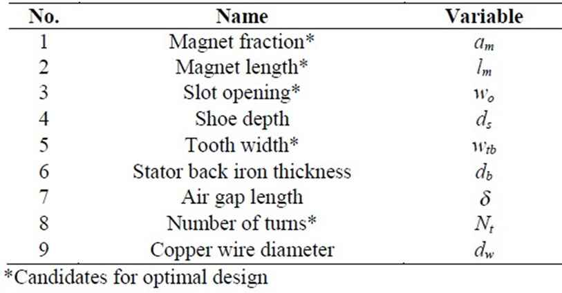
Table 6. Design variables for sensitivity analysis

Table 7. Predetermined variables for sensitivity analysis

Figure 4. Sensitivity index of (a) output torque, (b) torque density, (c) torque ripple, and (d) efficiency
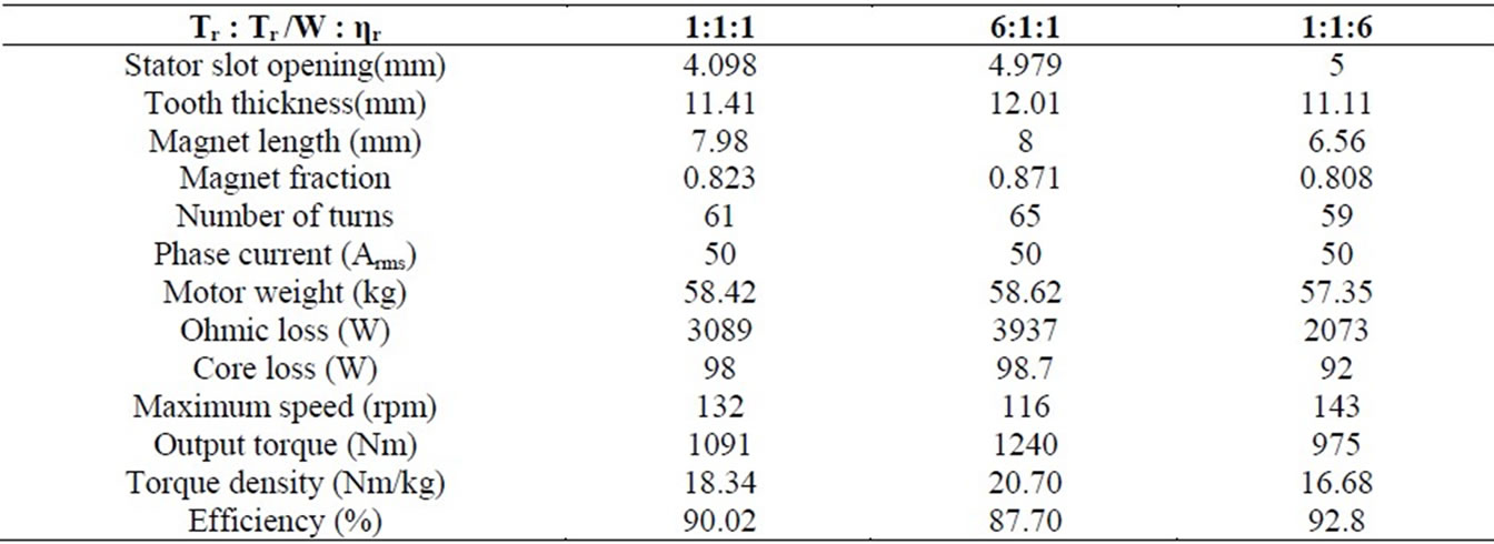
Table 8. Optimized motor variables and performance
The example of column 6:1:1 with the highest weighting on torque has the highest torque and torque density, but yields the worst performance in ohmic and core loss, maximum speed and efficiency among the three examples. Finally, the optimization result with equally important weightings on the three objectives, column 1:1:1, presents a balanced and satisfactory performance in torque, torque density and efficiency, and is chosen for the FE verification and refinement.
5. Finite Element Verification and Refinement
The 3D FE analysis is responsible for verifying the effectiveness of the 2D optimal design by including nonlinear characteristics. Owing to the symmetric structure, a quarter section of the motor with a half electric period is sufficient to model and analyze the expected performance. The resulting motor performance by the FE verification is shown in Table 9. It is also expected that the FE refinement through the adjustment of motor geometries, such as shoe depth, slot opening and back iron thickness, must further improve the motor performance. Apparently, the torque density is increased because of the reduction of weight, and the torque ripple is also suppressed by reshaping the geometry of slot opening, tooth depth and back iron thickness.
6. Optimal Current Waveform
It has been proved that the maximum torque is produced if the phase current is proportional to the angular rate of change of the field flux of the motor [15]. In other words, the best current waveform is the same as the back EMF wave of the motor in order to produce the maximum torque with minimal current. The reduction of torque ripple in the previous design steps means the back EMF of the motor needs to be made as close as possible to a sinusoidal wave. Besides, the current phase shift may have some influence on the torque production especially for the configuration of similar numbers of slots and poles in the three-phase drive.
Figure 5(a) illustrates the minimum magnetic circuit model with 12 slots and 11 poles for the 48/44 machine, where the coils are arranged as AA’AA’B’BB’BCC’CC’, and coils A and A’ are wound in opposite directions. Figure 5(b) lays out the EMF vectors of windings, where the slots of coils A1, -B1, and C1 are distributed in 120°E (electric degrees) of phase offset and the best shift g of each phase current must lead them in 22.5°E, thereby remaining a balanced configuration. It was found that not only the torque increased 8.4%, but the ripple also decreased by changing the current shift from 0 to 22.5°E.
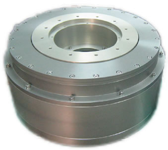
7. Prototype Fabrication and Experiments
The axial length of the motor was previously specified at 155 mm. To make the prototyping easier, it was downsized to 55 mm in view of precise machining and accurate assembling. Inevitably, such reduction of axial length must cause the rated torque to decrease by about 1/3 of the optimally designed motor. Figure 6(a) shows the stator core and concentrated windings, and the rotor assembly, glued on the outer surface of which are NeFeB 40SH magnets. A complete assembly of the torque motor is shown in Figure 6(b).
The performance of the prototype motor was tested with the voltage supply of 220V. Figure 7 compares the back EMF waveforms from the FE analysis and experiment, where both curves are close to the pure sine function, but the error between the experimental back EMF and pure sine function is even less than 5%. It is also interesting to point out that the back EMF constant from the experiment is 4.48 V/rad/s, which is very close to 4.57 V/rad/s from the FE analysis. Figure 8 shows the relationship between the torque and current, where Tmag=31.2Irms is for the magnetic circuit model, TFE=30.7Irms for the FE analysis and Texp=33.7Irms+5.43 for the experiment. The measured torque constant 33.7 Nm/A from the experiment is close to but slightly higher than those from the magnetic circuit model and FE analysis, partially because the measured torque may include additional friction from the bearing of the motor assembly. The offset of 5.434 Nm may account for the friction in bearing or inevitable measurement errors.
8. Summary and Conclusions
A systematic approach of design and control for a permanent magnet synchronous torque motor for machine tools was proposed. The design procedure was illustrated step by step in the order of specification, preliminary
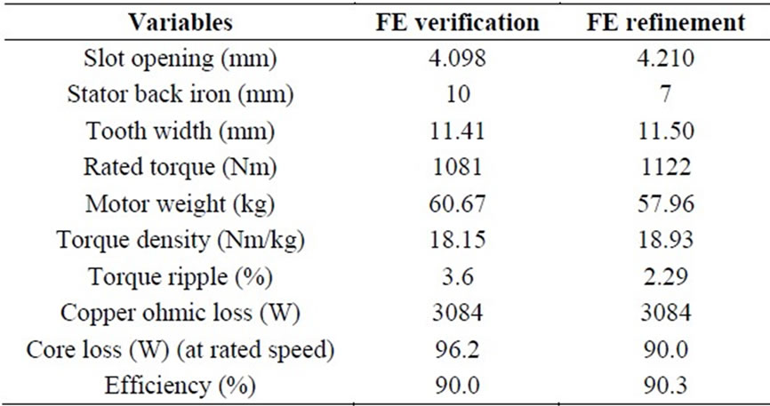
Table 9. FE verification and refinement
 (a)
(a) (b)
(b)
Figure 5. (a) Minimum magnetic circuit model of the 48/44 machine, and (b) its balanced winding layout
 (a)
(a)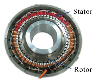 (b)
(b)
Figure 6. (a) Stator, rotor, and (b) their assembly of motor prototype
design, optimal design, finite element verification and refinement, and optimal control current waveform. These procedures help an engineer perform a complete design without missing any key issues. The sensitivity analysis and multifunctional optimization provide efficient and essential information for the designer to make a final decision for motor geometry. The precise finite element tool not only verifies but also refines the preliminary and
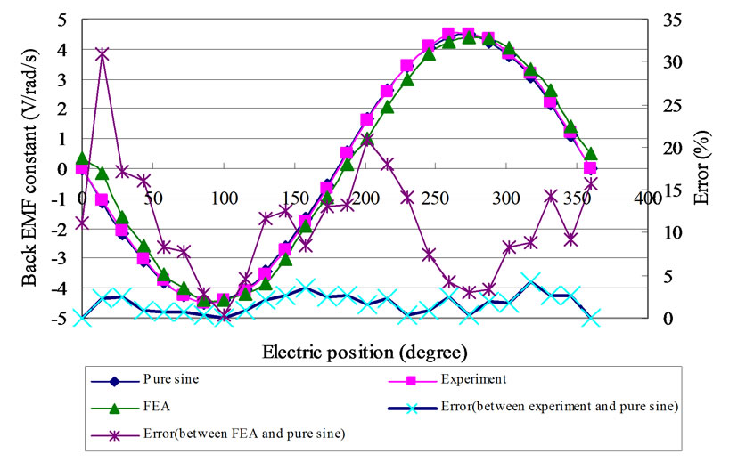
Figure 7. Back EMF waves from FE analysis and experiment
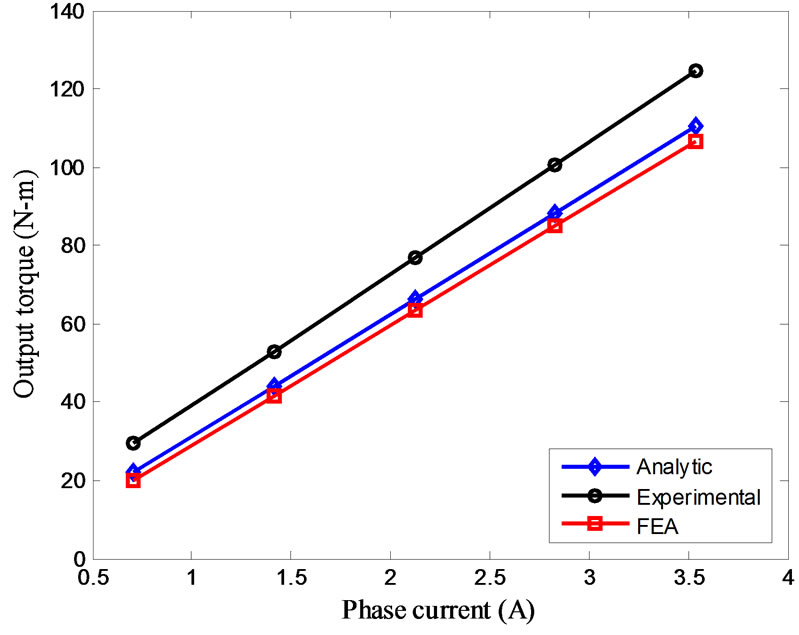
Figure 8. Torque constant curves
optimal design of the machine by improving its performance. The determination of optimal current waveform and phase shift further allows the machine to operate at its best capacity. Finally, the experiments on a prototype presented satisfactory performance in terms of back EMF wave, back EMF constant and torque constant, thereby validating the effectiveness of the optimal design and control strategy. The proposed design approach must facilitate motor designs in an effective way, especially for an engineer of little experience. The only deficiency of this study is the necessity of creating magnetic circuit models which differ from motor types and are only best approximated in two dimensions under various linear assumptions.
9. Acknowledgments
This work was supported by National Science Council of Taiwan, China, under Contract NSC95-2221-E-002-132- MY2.
REFERENCES
- B. Stumberger, G. Stumberger, M. Hadziselimovic, A. Hamler, M. Trlep, V. Gorican, and M. Jesenik, “Highperformance permanent magnet brushless motors with balanced concentrated windings and similar slot and pole numbers,” Journal of Magnetism and Magnetic Materials, Vol. 304, pp. e829–e831, 2006.
- D. Ishak, Z. Q. Zhu, and D. Howe, “Comparison of PM brushless motors, having either all teeth or alternate teeth wound,” IEEE Transactions on Energy Conversion, Vol. 21, pp. 95–103, 2006.
- C. C. Hwang, S. P. Cheng, and C. M. Chang, “Design of high-performance spindle motors with concentrated windings,” IEEE Transactions on Magnetics, Vol. 41, pp. 971–973, 2005.
- J. Cros and P. Viarouge, “Synthesis of high performance PM motors with concentrated windings,” IEEE Transaction on Energy Conversion, Vol. 17, pp. 248–253, 2002.
- M. F. Hsieh and Y. S. Hsu, “An investigation on influence of magnet arc shaping upon back electromotive force waveforms for design of permanent-magnet brushless motors,” IEEE Transactions on Magnetics, Vol. 41, pp. 3949–3951, 2005.
- M. S. Islam, S. Mir, T. Sebastian, and S. Underwood, “Design considerations of sinusoidally excited permanent-magnet machines for low-torque-ripple applications,” IEEE Transactions on Industry Applications, Vol. 41, pp. 955–962, 2005.
- Y. P. Yang, W. C. Huang, and C. W. Lai, “Optimal design of rim motor for electric powered wheelchair,” IET Electric Power Applications, Vol. 1, pp 825–832, 2007.
- T. M. Jahns and W. L. Soong, “Pulsating torque minimization techniques for permanent magnet AC motor drives-a review,” IEEE Transactions on Industrial Electronics, Vol. 43, pp. 321–330, 1996.
- T. F. Chan, W. Wang, P. Borsje, Y. K. Wong, and S. L. Ho, “Sensorless permanent-magnet synchronous motor drive using a reduced-order rotor flux observer,” IET Electric Power Applications, Vol. 2, pp. 88–98, 2008.
- T. Kim, H. W. Lee, and M. Ehsani, “Position sensorless brushless DC motor/generator drives: Review and future trends,” IET Electric Power Applications, Vol. 1, pp. 557–564, 2007.
- Y. P. Yang and D. S. Chung, “Optimal design and control of a wheel motor for electric passenger cars,” IEEE Transactions on Magnetics, Vol. 43, 2007, pp. 51–61.
- Z. Q. Zhu and D. Howe, “Influence of design parameters on cogging torque in permanent magnet machines,” IEEE Transactions on Energy Conversion, Vol. 15, 2000, pp. 407–412.
- V. Ostovic, “Computer-aided analysis of electric machines,” New York: Prentice Hall, 1994.
- C. T. Tseng, W. C. Liao, and T. C. Tang, “MOST user's manual,” in Mechanical Engineering, 1.2ed Taiwan, Hsinchu: National Chiao-Tung University, 1993.
- Y. P. Yang, Y. P. Luh and C. H. Cheung, “Design and control of axial-flux brushless dc wheel motors for electric vehicles – Part I: multi-objective optimal design and analysis,” IEEE Transactions on Magnetics, Vol. 40, No. 4, July 2004, pp.1873–1882.