Int'l J. of Communications, Network and System Sciences
Vol.7 No.7(2014), Article ID:48123,7 pages
DOI:10.4236/ijcns.2014.77025
Amplify and Forward Relaying Systems for Collocated Antennas
Mahmud Al-Naser, Salem Salamah
Department of Electronic Engineering Technology, Public Authority of Applied Education and Training, Al Shuwaik, Kuwait
Email: mj.alnaser@paaet.edu.kw, sh.salamah@paaet.edu.kw
Copyright © 2014 by authors and Scientific Research Publishing Inc.
This work is licensed under the Creative Commons Attribution International License (CC BY).
http://creativecommons.org/licenses/by/4.0/


Received 22 May 2014; revised 22 June 2014; accepted 10 July 2014
ABSTRACT
Cooperative relaying for a system that consists of different configurations of a collocated and uniform linear antenna is analyzed. The amplify-and-forward relaying (AF) and selection combining (S-AF) schemes based on maximal ratio combining (MRC) method for singleand multi-relay are investigated. In this study, the bit-error-rate (BER) expression for collocated and uniform linear antenna in cooperative communication system over flat Rayleigh fading channel is derived. The result for 3-element collocated antennas (tripole) shows improvement in performance over dual-polarized antennas. Also increasing number of tripole antenna does not add improvement.
Keywords: Cooperative Communications, Fading Channels, Relay, Antennas

1. Introduction
Relay systems have been widely investigated in wireless communications as a way to overcome deep fading and therefore enhance signal quality in multi-path fading channels. In relaying network we have a two-hop link where the signal is transmitted in the first hop from a source to a relay node and in the second hop the signal at the relay node is retransmitted to the destination. At the same time, the source will transmit another copy of the signal directly to the destination. Therefore, the signal is transmitted from the source directly and via a relay node, so, the destination will receive the transmitted signal from two links referred as source-relay-destination and source-destination link. Now the signal received at the relay is forwarded to the destination by implementing two schemes known as amplify forward (AF) and decode forward (DF) [1] -[3] . In AF, the received signal at relay is amplified and re-transmitted. In DF, the received signal at relay is decoded then retransmitted again to destination. Earlier research was focused on employing singleand multi-antenna system for cooperative diversity technique to exploit fading channels [3] [4] . In [3] , the symbol error probability was derived for dual hop with single antenna in Rayleigh and Nakagami m-fading channels and the outage performance of communication system was investigated for AF and DF relaying network. Cooperative communication for a multi-relay network with multiple-input multiple-output network to exploit spatial diversity is investigated in [4] . Here, the relays and users cooperate in sharing information which in turn increases capacity and coverage area of wireless communications. Other techniques utilizing relays equipped with multi-antennas and multi-relay network are investigated where an infrastructure-based relaying deploying multi-antennas on a relay is presented in the work of Adinoyi et al. [5] . To decrease number of relay nodes and thus reducing cost, a single antenna is deployed at source and destination while multi-antennas are fixed on receiver side of relays. The receiver criterion is based on threshold relaying with MRC and selection combining. Also cooperative communication is studied when relay selection scenario applied for the best relay link. It was shown that selection relaying can achieve same diversity order as AF [6] -[8] . Furthermore, deploying multi-antennas at the source or relays receiver side shows improvement as number of antennas increased from 1 to 2 for high and low SNR but increasing antennas more than 2, did not add significant improvement in performance at high SNR [9] [10] .
Since future wireless system trends require wireless terminals small in size, the advantage of using multiple antennas at a relay node will be limited by the space separation between antennas and thus correlation of wireless terminals will affect the system performance. In this paper the study of cooperative communication is applied for collocated antennas known as “vector antenna” (VA) implemented at a relay node over independent and identically distributed Rayleigh fading channels. Vector antenna can independently detect or excite all six EM field components enabling the communication system to access additional signaling dimensions, which may enhance performance in the same way as antenna arrays [11] . These extra dimensions can provide additional diversity to combat signal fading, allow the system to spatially leverage bandwidth by transmitting multiple separable signals in the same bandwidth, and improve the suppression of interference in a multiuser environment. Also, “tripole” antenna that consists of three mutually-orthogonal dipoles by Andrew et al. [12] have shown through simulation, that this antenna improves on the capacity of scalar and dual-polarized antennas for a simple propagation example involving a line-of-sight component and one reflected path. The end-to-end performance for a relay network employing vector and ULA antennas based on MRC are investigated and using AF and selection schemes and an expression for bit error rate for BPSK is derived. Since we are investigating the advantage of collocated antennas in relay network, AF and selection schemes are selected.
The organization of this paper is as follows: in Section 2 the system model is introduced for VA and ULA in a relay network and the output SNR is analyzed. In Section 3 the BER analysis for AF and S-AF schemes is presented. Finally, simulation of the system presented is compared with theoretical values of the equation derived.
2. System Model
BPSK modulation is considered for a relay communication network that consists of two-hop channel as shown in Figure 1. In the first hop signals are transmitted from a single linear antenna at the source to the receiver side of relay node and in the second hop the received signal is transmitted from the transmitter side of relay node to the destination. The receiver side of the relay node is equipped with a vector antenna and the transmitter side with a uniform linear antenna. The source and destination nodes will use a single linear antenna. The channel assumed to be flat fading slowly time varying and the direct link from source to destination is considered only in S-AF.
For a single vector antenna at the receiver side of relay node, each arriving multipath
component is a twodimensional vector , consist of horizontally and vertically
polarized components of the electric field. For narrowband sinusoidal signals, it
is convenient to write the signal in terms of its complex envelope Z, where
, consist of horizontally and vertically
polarized components of the electric field. For narrowband sinusoidal signals, it
is convenient to write the signal in terms of its complex envelope Z, where
 , and
, and
 is the carrier frequency. For any polarized signal, the complex envelope can be
written as
is the carrier frequency. For any polarized signal, the complex envelope can be
written as
 (1)
(1)
where
 are the amplitude, phase, orientation angle, and ellipticity angle, respectively
[13] . Since the signal is a function of the
transmitted data, the amplitude, phase and polarization angles vary with time, and
are the amplitude, phase, orientation angle, and ellipticity angle, respectively
[13] . Since the signal is a function of the
transmitted data, the amplitude, phase and polarization angles vary with time, and
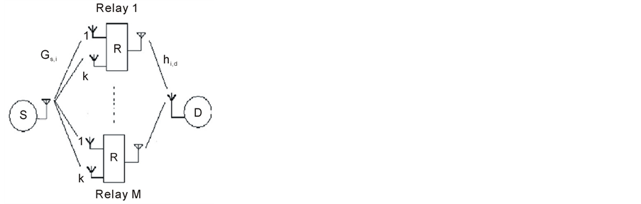
Figure 1. Multi-relays system with vector antenna and ULA.
we write .
.
If the multipath component is reflected or scattered by an object in the far field,
then the signal can be approximated as a plane wave at the receiver and suppose
that the multipath component arrives at the sensor from the direction ,
,
 (2)
(2)
nonconductive, homogeneous, and isotropic medium, the received signal can be modeled by [13]
 (3)
(3)
where
 represents thermal noise,
 and
and
 denote the three-dimensional complex envelopes of the electric and magnetic field
vectors respectively at the receiver,
denote the three-dimensional complex envelopes of the electric and magnetic field
vectors respectively at the receiver,
 is the intrinsic impedance of the propagation medium, and
 (4)
(4)
The
 vector antenna system will be used to detect information signal at receiver in the
relay system of interest. The transmitted signal of a complex baseband signal of
the form
vector antenna system will be used to detect information signal at receiver in the
relay system of interest. The transmitted signal of a complex baseband signal of
the form
 (5)
(5)
where
 is a sequence of transmitted information bits. When
 is transmitted, the horizontally and vertically polarized components of each multipath
component consist of
is transmitted, the horizontally and vertically polarized components of each multipath
component consist of
 with some amplitude and phase shift, so that
 for some fixed complex vector
 Then the received signal can be written as
 (6)
(6)
with relay system notation, we can write the received signal from source to relay to be
 (7)
(7)
where
 is number of relays and
 is the transmitted power for the source and
 reflects the change in amplitude, phase, and polarization experienced by the fading
component as it propagates from the source to relay. The noise
reflects the change in amplitude, phase, and polarization experienced by the fading
component as it propagates from the source to relay. The noise
 is zero-mean complex Gaussian vector with covariance
 . With abuse of notation we can write above equation
at relay as
. With abuse of notation we can write above equation
at relay as
 (8)
(8)
where each of
 consists of the appropriate
 components of
 . The components of the vector
 are modeled as i.i.d. zero-mean complex Gaussian random variables and therefore
the elements of
are modeled as i.i.d. zero-mean complex Gaussian random variables and therefore
the elements of
 are also zero-mean complex Gaussian random variables. The output of MRC at the relay
is given by:
are also zero-mean complex Gaussian random variables. The output of MRC at the relay
is given by:
 (9)
(9)
where
 is the SNR of the
 relay. The noise
 is white and assuming equal SNR on all branches. The received signal from
 relay at destination
 (10)
(10)
where
 is the channel gain from relay node to destination and the gain at the
 relay can be written as
 (11)
(11)
The noise
 and
and
 are additive-white-Gaussian noise (AWGN) with zero mean and variance
 and
and
 is the transmitted power at the relay. At destination the receiver employ a maximal
ratio combining algorithm and the received end-to-end SNR is given by
is the transmitted power at the relay. At destination the receiver employ a maximal
ratio combining algorithm and the received end-to-end SNR is given by
 (12)
(12)
The output SNR at destination can be re-written as
 (14)
(14)
where
 is the SNR at
 relay and
 is the SNR at destination from
 relay. The SNR
 and
and
 are independent and identically distributed. Since the SNR is not mathematically
tractable hence for high SNR it can be upper bounded by
are independent and identically distributed. Since the SNR is not mathematically
tractable hence for high SNR it can be upper bounded by
 (15)
(15)
To simplify the analysis, the noise is ignore at the relay gain. The output SNR of MRC at relay for tripoleatenna is exponentially distributed and follows the Gamma distribution with probability density function pdf given by
 (16)
(16)
where
 is number of tripole antennas at the relay and the pdf of SNR at destination is
given by:
is number of tripole antennas at the relay and the pdf of SNR at destination is
given by:
 (17)
(17)
Now using the results in [9]
[10] , the moment generation function of
 is given by:
 (18)
(18)
where .
.
3. Error Rate Analysis
3.1. Amplify Forward (AF)
Assuming independent of , the bit error rate can be
derived based on MGF approach in [14]
that can be written as
, the bit error rate can be
derived based on MGF approach in [14]
that can be written as
 (19)
(19)
where
 for BPSK modulation and independent of
 .
.
3.2. Selective Amplify Forward (S-AF)
For S-AF only the best relay which contributes most to received SNR is chosen for re-transmission. The received SNR can be expressed as
 (20)
(20)
The received SNR for S-AF can be written as
 (21)
(21)
where
 and
and . At high SNR region, using the result in
[6] for approximation of cumulative
distribution function (CDF) of the received SNR for S-AF scheme, the CDF for tripole
antenna is given by
. At high SNR region, using the result in
[6] for approximation of cumulative
distribution function (CDF) of the received SNR for S-AF scheme, the CDF for tripole
antenna is given by
 (22)
(22)
where
 and
and
 is exponentially distributed with pdf
 . Substituting Equation (22)
in
 [[6] , equation
(6)] and using
[[6] , equation
(6)] and using . The high SNR approximation
can be written as
. The high SNR approximation
can be written as
 (23)
(23)
4. Simulation Results
In this section, simulation and theoretical results of cooperative communication
for AF and S-AF schemes presented. We assume that the multipath components of the
received signals are uniformly distributed on a sphere where the azimuth angle
 are i.i.d. and uniform on
 , and the elevation angles
 are i.i.d. with probability density function
 (24)
(24)
and the polarizations
 are i.i.d. CN(0, I). The noise
 is spatially and temporally white and Gaussian
(i.e. ). The fading channel is assumed to be a flat fading Rayleigh
channel. The transmitted power for all participate scheme on each relay is
). The fading channel is assumed to be a flat fading Rayleigh
channel. The transmitted power for all participate scheme on each relay is , where
 is the relay number and total transmitted power
 . In selective scheme, the transmitted
power for each relay is
. In selective scheme, the transmitted
power for each relay is . The antenna setting in all simulation will
be based on the following setting: the source, destination and transmitter side
of the relay will employ ULA while the receiver side relay will have vector antenna
that consist of either dual, tripole or 6-element antennas as specified in the figures
below.
. The antenna setting in all simulation will
be based on the following setting: the source, destination and transmitter side
of the relay will employ ULA while the receiver side relay will have vector antenna
that consist of either dual, tripole or 6-element antennas as specified in the figures
below.
In Figure 2, the results are plotted for 1, 2 and 3 relays where each relay will assume a single tripole antennas. Simulation and theoretical BER are compared. The figure shows that as number of relays increase, BER will decrease and therefore increase of diversity gain. On the other hand the theoretical results came in a very close approximation to our simulation. In Figure 3, the results shows an increase in the number of tripole antennas on
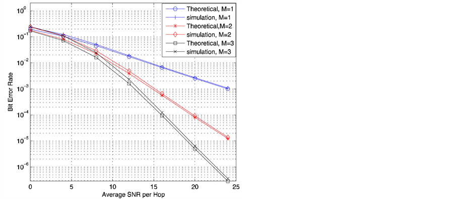
Figure 2. BER for tripole antenna with multi-relays.
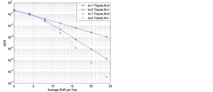
Figure 3. BER simulation for tripole antenna at single and multi-relays.
a relay did not add gain in diversity to the relay system while multi-relay network with single triple antenna would give us significant improvement.
In Figure 4, simulation of 2, 3 and 6-element collocated antenna for one relay are compared. The results show that a 2 dB gain at low SNR region for 6 over 2 elements collocated antennas but no gain is noticed in the high SNR region. In Figure 5, selective relaying simulation for 2 and 3 relay network is presented. The relay with highest SNR is chosen where each relay is equipped with one tripole antennas. As the number of relays increased, diversity improve and on the same figure BER for selection is compared with all participate scheme. The results show that selection (S-AF) outperforms AF scheme in all cases considered.
5. Conclusion
The study of cooperative communication for collocated antennas setting employed at relay node and ULA at source and destination is investigated. Two schemes of relaying network known as AF and S-AF are presented and closed form BER for tripole antennas is derived. The theoretical and simulation results are compared for oneand multi-relay network. Results shows that tripole antenna outperformed the dual antenna case and the 6-
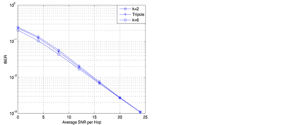
Figure 4. BER simulation for 2, 3 and 6 collocated antennas at single relay.
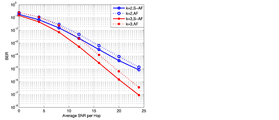
Figure 5. BER Simulation
for selective vs AF for tripole and
 relay.
element vector antenna can add more gain in low SNR region over tripole case. Also increasing number of tripole antenna showing no gain is attained while increasing number of relays will enhance the receiver performance and achieve higher gain.
References
- Emamian, V., Anghel, P. and Kaveh, M. (2002) Multi-User Spatial Diversity in a Shadow-Fading Environment. IEEE Vehicular Technology Conference, 1, 573-576.
- Sendonaris, A.,
Erkip, E. and Aazhang, B. (2003) User Cooperation Diversity. Part I. System Description.
IEEE Transactions on Communications, 51, 1927-1938.
http://dx.doi.org/10.1109/TCOMM.2003.818096 - Hasna, M.O. and Alouini, M.S. (2003) End-to-End Performance of Transmission Systems with Relays over Rayleigh-Fading Channels. IEEE Transactions on Wireless Communications, 2, 1126-1131. http://dx.doi.org/10.1109/TWC.2003.819030
- Laneman, J.N. and Wornell, G.W. (2003) Distributed Space-Time-Coded Protocols for Exploiting Cooperative Diversity in Wireless Networks. IEEE Transactions on Information Theory, 49, 2415-2425. http://dx.doi.org/10.1109/TIT.2003.817829
-
Adinoyi, A. and Yanikomeroglu, H. (2007) Cooperative Relaying in Multi-Antenna Fixed
Relay Networks. IEEE Transactions on Wireless Communications, 6, 533-544.
http://dx.doi.org/10.1109/TWC.2007.05227 - Zhao, Y., Adve, R. and Lim, T.J. (2006) Symbol Error Rate of Selection Amplify-and-Forward Relay Systems. IEEE Communications Letters, 10, 757. http://dx.doi.org/10.1109/LCOMM.2006.060774
- Zhao, Y., Adve, R. and Lim, T.J. (2006) Improving Amplify-and-Forward Relay Networks: Optimal Power Allocation versus Selection. IEEE International Symposium on Information Theory, 1234-1238.
- Ikki, S. and Ahmed, M. (2008) Performance of Multiple-Relay Cooperative Diversity Systems with Best Relay Selection over Rayleigh Fading Channels. EURASIP Journal on Advances in Signal Processing, 2008, Article ID: 580368. http://dx.doi.org/10.1155/2008/580368
- Min, H., Lee, S., Kwak, K. and Hong,
D. (2009) Effect of Multiple Antennas at the Source on Outage Probability for Amplify-and-Forward
Relaying Systems. IEEE Transactions on Wireless Communications, 8, 633-637.
http://dx.doi.org/10.1109/TWC.2009.071332 - Dey, A., Ghosh, P.K. and Gupta, K. (2011) On the Performance Analysis of Multi-Antenna Relaying System over Rayleigh Fading Channel. International Journal on Control System & Instrumentation, 2, 46.
- Naguib, A.F. and Paularj, A. (1994) Performance of CDMA Cellular Networks with Base-Station Antenna Arrays. Proceedings of International Zurich Seminar on Digital Communications, 1-5 May 1994, 87-100.
- Andrews, M.R., Mitra, P. and De Carvalho, R. (2001) Tripling the Capacity of Wireless Communications Using Electromagnetic Polarization. Nature, 409, 316-318. http://dx.doi.org/10.1038/35053015
- Nehorai. A. and Paldi, E. (1994) Vector-Sensor
Array Processing for Electromagnetic Source Localization. IEEE Transactions on Signal
Processing, 42, 376-398.
http://dx.doi.org/10.1109/78.275610 - Simon, M.K. and Alouini, M.S. (2000) Digital Communication over Fading Channels: A Unified Approach to Performance Analysis. Wiley, New York. http://dx.doi.org/10.1002/0471200697