Int'l J. of Communications, Network and System Sciences
Vol.5 No.11(2012), Article ID:24669,7 pages DOI:10.4236/ijcns.2012.511077
Employing Power Allocation to Enhance Zero Forcing Scheme Advantages over Multi-Antenna Multiple Relay Networks
Department of Electrical Engineering (DCCS Lab), Iran University of Science and Technology, Tehran, Iran
Email: afalahati@iust.ac.ir
Received January 21, 2012; revised July 11, 2012; accepted September 16, 2012
Keywords: Cooperative Communication; MIMO; Multiple Antennas Multiple Relay (MAMR) Networks; Zero Forcing; Power Allocation
ABSTRACT
A multi-antenna multiple relay (MAMR) network is considered and a variation of two-hop zero-forcing amplify-forward relaying method is proposed. Deploying ZF method together with application of diagonal power allocation matrices at the relays, it is shown that the overall MAMR network is simplified to M independent single antenna multiple relay (SAMR) networks, where M is the number of source and destination antennas. This enables to incorporate network beamforming proposed for SAMR networks. Accordingly, using the BER as the performance metric, we present simulation results to show the proposed approach outperforms the common ZF method addressed in the literature.
1. Introduction
It is well established that in most cases relaying techniques provide considerable advantages over direct transmission, provided that the source and relay cooperate efficiently. The choice of relay function is especially important as it directly affects the potential capacity benefits of node cooperation [1-5]. In this regard, two relaying methods, Amplify-Forward (AF) [6,7] and estimate-forward (EF) [8,9], are extensively addressed in the literature. As the names imply, the former just amplifies the received signal but the latter estimates the signal with errors and then forwards it to the destination.
It has been shown that increasing the number of relays has the advantage of increasing the diversity gain and flexibility of the network. However, it renders some new issues to arise [10]. For instance, the relaying algorithm and power allocation across relays should be addressed in such cases. Relay selection [11,12] and power allocation [13,14] are two well-known methods when the power management issues are dealt with.
The capacity and reliability of the relay channel can be further improved by using multiple antennas at each node. The use of relays together with multiple antennas has made it a versatile technique to be used in emerging wireless technologies [15-20]. Relaying strategies for the multi-antenna multiple relay (MAMR) network are more challenging than single antenna network.
AF Multi-Input Multi-Output (MIMO) relay systems have drawn considerable attention in the literature due to their simplicity and ease of implementation. In this regard, a plethora of works are devoted to finding a proper relaying strategy for AF MAMR networks. In [21], the idea of linear distributed multi-antenna relay beamforming (LDMRB) is introduced where each relay performs a linear reception and transmission in addition to output power normalization. The linear operations suggested in this paper are Matched Filter (MF), Zero Forcing (ZF) and Minimum Mean Square Error (MMSE). They are briefly called MF-MF, ZF-ZF and MMSE-MMSE schemes, respectively. In [22], a method based on QR decomposition is suggested which has better performance than the ZF-ZF scheme. Combinations of various schemes are also considered in [22].
In [23], the so-called incremental cooperative beamforming is introduced and it is shown that it can achieve the network capacity in the asymptotic case for large K with a gap no more than.
In [24], a wireless sensor network composed of a few multi-antenna sensors aimed to transmit a noisy measurement vector parameter to the fusion centre is formulated as a MAMR network.
In [25], it is shown that a MAMR network with single antenna source and destination can be transformed into a single antenna multiple relay (SAMR) network by performing Maximal Ratio Combining (MRC) at reception and transmission for each relay nodes. This enables the network beamforming introduced in [14] to be readily employed. Indeed, this manuscript is an extension of [25] where, here we assume the K independent sources send independent data streams to their respected single antenna destinations.
Latest developments are mentioned as the LDMRB to enhance its performance i.e. in [26] MF and MSE are used in reception and transmission of each relay respectively. Although the performance of this method is better than the proposed method in the current paper, but the current paper is to apply power allocation between relays in ZF-ZF scheme and can be developed further in the future. Furthermore it is noteworthy that recent papers on this subject use numerical optimization to find the optimized relay matrices, i.e. [27] but these methods are too complicated to implement. Thus we compare the proposed method with its ancestor (ZF-ZF) method.
In this paper, the idea of LDMRB is used where ZF algorithm is utilized in both reception and transmission. It is shown that using this method the overall MAMR network can be transformed into M independent SAMR networks. Then the idea of network beamforming that is suggested in [14] for SAMR network can be used to allocate power to any data streams in relays. In other words, in each relay at first the transmitted vector is estimated using ZF and then based on the network beamforming algorithm [14], the power of each element of the estimated vector is controlled and then it is forwarded to the destination using ZF precoding.
Notations:  means the ith element of vector a,
  means the ith row of matrix A,
  means the entry corresponding to the jth column and ith row of matrix A.
2. The Relay Network System Model
Figure 1 illustrates a typical MAMR relay network system in which the source and destination have M antennas each. It is assumed that there are K multiple-antenna relays, each having 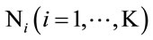 antennas and
 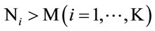 . Transmission occurs in two hops. During the first hop, the transmitter broadcasts the desired signal to the relays. Then, throughout the second hop, each relay applies a weight matrix to the received signal vector and retransmits it to destination.
We consider x as a M × 1 vector whose elements are independent zero mean random variables with covariance matrix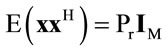 . Thus, the received signal vector at the ith relay can be represented as,
 (1)
(1)
where ni is a  noise vector, representing the received noise vector at the ith relay with the covariance
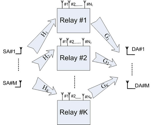
Figure 1. A typical MAMR relay system model.
matrix  where
where  denotes the identity matrix and N0 is the noise power associated with each entry
 .
.  is
is  matrix to represent the channel gain matrix between the transmitter and the ith relay. It is assumed that the entries of Hi are zero mean unit variance drawn from an independent complex Gaussian distribution. But Hi’s are known at all relays. Moreover, (.)H is a Hermitian operation. Assuming the ith relay multiplies its received signal by a weight matrix
  and forwards the resulting vector
  to the destination, it follows that:
 (2)
(2)
 (3)
(3)
where  is the average transmit power which is assumed to be lower than
 , considering
  is frobenius norm. Thus, referring to Figure 1:
 (4)
(4)
where  is the ith
  channel gain matrix between the ith relay and the destination whose entries are zero mean unit variance complex Gaussian random variables.
 ’s are known at all relays. Also, n is a M × 1 zero-mean noise vector whose entries are of power N0. Finally, ni for
  and n are assumed to be statistically independent. Moreover, in this work it is assumed that no processing is performed at the receiver. In other words, the weight matrices Wi for
  are computed such that the received vector y is a scaled unbiased estimate of the transmitted vector x.
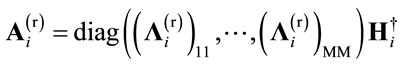
3. The ZF-ZF LDMRB Scheme
Suppose a linear MAMR relay in which the relay performs linear operations at both reception and transmission. One can decompose the relay weight matrix  to three sub-matrices namely; reception
 , power control
  and transmission
  matrices as:
 (5)
(5)
where the superscripts (t), (p) and (r) indicate transmission, power allocation and receiving operations, respectively. Moreover, ![]() is a diagonal matrix with positive fractional diagonal elements. This matrix is used to control the power assigned to each symbol stream.
is a diagonal matrix with positive fractional diagonal elements. This matrix is used to control the power assigned to each symbol stream.
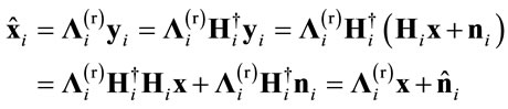
Considering the estimated transmitted vector at the ith relay as:
 (6)
(6)
Thus, one can rewrite the transmitted symbol of the ith relay as:
 (7)
(7)
In [21], it is shown that in the absence of power allocation , the Zero Forcing weight matrix at the ith relay can be written as:
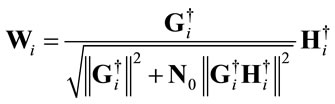 (8)
(8)
where  is the pseudo inverse operation. The denominator ascertains the output power normalization. In this case, the receiving matrix in (5) can be considered as:
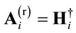 (9)
(9)
and similarly, we have:
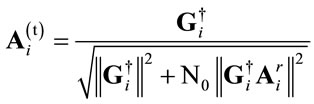 (10)
(10)
So the estimated or demodulated vector of the ith relay becomes:
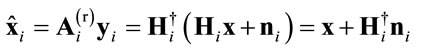 (11)
(11)
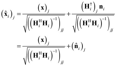
Here it is assumed that the number of relay antennas  is larger than that of source and destination antennas i.e. Ni > M. Moreover, the resulting noise vector at the ith relay is
 . As a result, the jth element of the estimated vector at ith relay becomes:
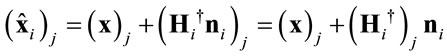 (12)
(12)
Note that, the jth entry of the resulting noise vector at the ith relay is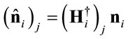 , thus one can readily compute its power (
 ) as:
) as:
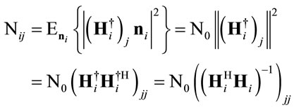 (13)
(13)
If the receiving matrix is redefined as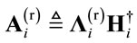 , where
  is a diagonal matrix whose diagonal entries are
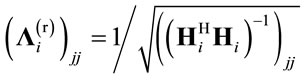 , then the receiving matrix can be written as:
 (14)
(14)
The demodulated symbol at the ith relay can now be written as:
 (15)
(15)
Thus the jth entry of  is obtained as:
 (16)
(16)
where N0 is the power of 
Substituting  from (15) into (7), the transmitted vector of the ith relay can be written as:
 (17)
(17)
where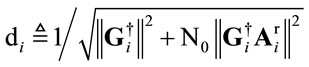 .
.
Thus, substituting  from (17) into (4), the received signal at the destination becomes:
 (18)
(18)
As a result, the jth element of the received vector at destination or the received symbol at the jth destination antenna can be represented as:
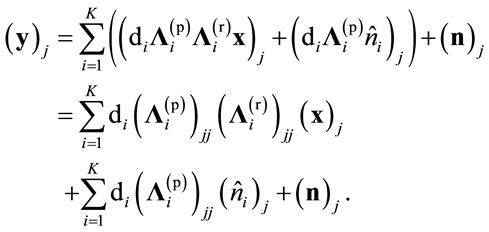 (19)
(19)
It can be seen that all interferences are canceled using zero forcing scheme and the symbol received in the jth destination antenna just depends on the symbol transmitted by the jth source antenna. This resembles to a SAMR network. Therefore, we have M independent SAMR network and hence the so called network beamforming can be applied.
4. The Power Allocation Algorithm
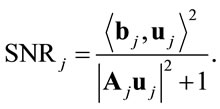
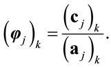
The SNR of the received symbol at the jth destination antenna can be computed as,
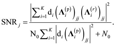 (20)
(20)
It is desired to find ![]() to maximize SNR for all data streams. As noted earlier,
to maximize SNR for all data streams. As noted earlier, ![]() is a diagonal matrix whose diagonal entries are positive number taking values less than one.
is a diagonal matrix whose diagonal entries are positive number taking values less than one.  identifies the fraction of power that is allocated by the ith relay to the jth data stream. As noted in [14], symbol streams that have less SNRs have to be transmitted with less power, similarly Good symbol streams have to be transmitted with full power. The elements of
 ![]() control the fraction of power that assigned to each symbol stream.
control the fraction of power that assigned to each symbol stream.
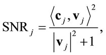
N0 is a constant term and thus, can be discarded from optimization. We define the following vectors and matrix associated with the jth symbol stream as follows,
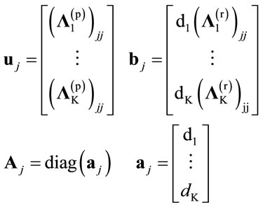 (21)
(21)
The SNR can now be written as:
 (22)
(22)
This relation is similar to the network beamforming problem for single antenna network [14]. Hence, one can apply the optimal power allocation proposed in [14] by Jing et al. If we define 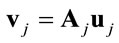 then:
then:
 (23)
(23)
where,
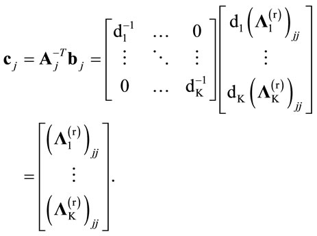 (24)
(24)
where  is the inverse of the transpose of matrix A.
The Jing algorithm [14] is briefly presented here. At first, each relay computes the following parameters:
 (25)
(25)
These are also computed at destination. They are sorted in descending order as follows:
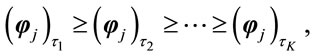 (26)
(26)
And  is defined to be
 . Then the parameter
 ![]() is also defined as:
is also defined as:
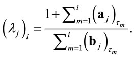 (27)
(27)
Then the optimal power allocation is obtained as:
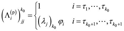 (28)
(28)
where k0 is the smallest k such that  [14].
[14].
This procedure is performed for all SAMR networks and ![]() for
for  is obtained.
The proposed method can be briefly explained as follows. At first, the receiving  and transmission
  matrices at each relay is computed from (14) and (10) respectively. This transforms the overall channel matrix from source to destination to a diagonal matrix. Power allocation matrix
 ![]() for
for  can be then obtained from (28). Finally, Relay matrices are computed by multiplication of the given matrices as
  for
for . The algorithm that presented here can be summarized as follows. In each relay the transmitted vector is estimated using ZF method. The using network beamforming the power of each element of the estimated vector is controlled. Not all elements can be transmitted with full power. The element that have SNR more that a threshold is transmitted with full power and remaining symbols are transmitted with a fraction of full power that have direct relation to their SNR. The power control values are obtained using network beamforming algorithm [14].
5. Simulation Results
In the simulation of a MAMR network here, the large scale fading experienced by the relays is assumed to be the same. The channel matrices are generated independently during subsequent iterations. It is also assumed that the first and second hop channels for all relays are known to all nodes. Furthermore, an uncoded QPSK modulation is used and independent symbol sequences is transmitted by each source antennas.
Figure 2 depicts the overall MAMR system BER performance for a network with 2 relays each with 2 antennas arranged for simulation. As it can be seen for all SNR values, the power allocated ZF method outperforms the ZF method without power allocation.
Figure 3 shows the BER simulation performance of networks with 4, 6 and 8 relays each with 4 antennas. In this figure, the numbers appeared after the scheme’s name in the legend box determine the number of nodes and nodes antennas. The first three numbers determines the number of nodes. For instance, 131 means one source, three relays and one destination. The next three numbers determines number of node’s antennas. For instance, 444 means source, relay and destination each have 4 antennas. In Figure 3 the effect of the number of relays on the performance of the network is evaluated. It can be seen that Increasing the number of relays, PA’s improvement increases and hence the gap between non power allocated and power allocated ZF increases.
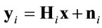
In Figure 4, the number of the source and destination antennas is kept fixed to 2. The number of relays is also fixed to 3 but the relays antennas number varies from 2 to 4. It can be observed that, by increasing the number of relays antennas, PA’s are improved further. This is indeed for the inevitable increase in diversity to allow more relays to transmit with their full power.
6. Conclusions
A new signaling method for Multi-antenna Multiple Relay networks (MAMR) with the aid of ZF-ZF method at
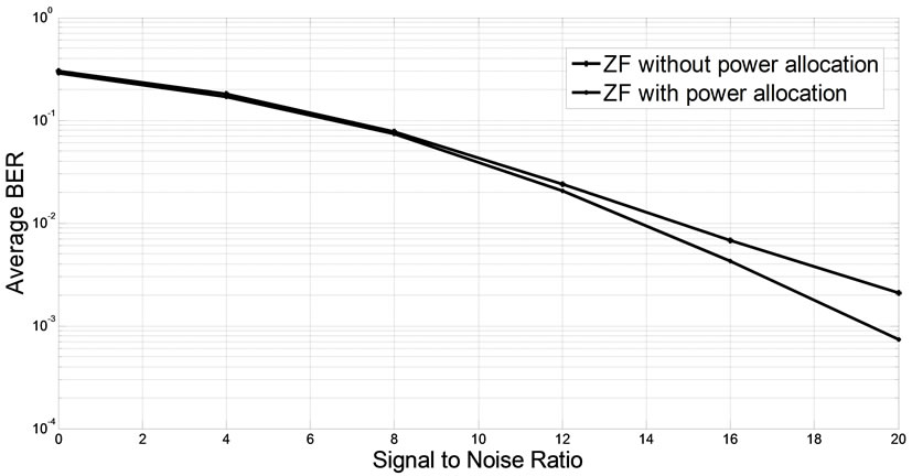
Figure 2. MAMR network with 2 relay each with 2 antennas.
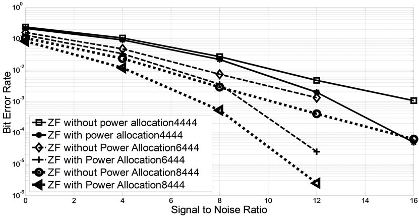
Figure 3. MAMR network with 4, 6 and 8 relays each with 4 antennas.
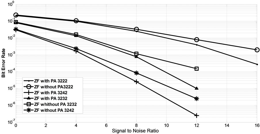
Figure 4. Comparison of the designed relay network with the same number of relays and various number of antennas.
the relays is proposed to transform the original network into several single-antenna relay networks. This helps to mitigate the interference term between individual data streams transmitted from the individual source antennas. Accordingly, the network beamforming which is proved to be the optimal power allocation method for SAMR network [14] is being used.
Simulation results indicate that the proposed method improves the BER comparing with the naive ZF-ZF method in the absence of power allocation.
Future works: the amount of power that is not used for one data stream in a relay can be used by other data stream. This is not considered in this paper and can be the subject for a future work. Also this method can be generalized to MMSE-MMSE and QR-QR schemes.
7. Acknowledgements
The authors thank ITRC (Iran Telecommunication Research Center) for supporting this project financially.
REFERENCES
- A. Sendonaris, E. Erkip and B. Aazhang, “User Cooperation Diversity, Part I: System Description,” IEEE Transactions on Communications, Vol. 51, No. 11, 2003, pp. 1927-1938. doi:10.1109/TCOMM.2003.818096
- D. Chen and J. N. Laneman, “Modulation and Demodulation for Cooperative Diversity in Wireless Systems,” IEEE Transactions on Wireless Communications, Vol. 5, No. 7, 2006, pp. 1785-1794. doi:10.1109/TWC.2006.1673090
- J. N. Laneman, D. N. C. Tse and G. W. Wornell, “Cooperative Diversity in Wireless Networks: Efficient Protocols and Outage Behavior,” IEEE Transactions on Information Theory, Vol. 50, No. 12, 2004, pp. 3062-3080. doi:10.1109/TIT.2004.838089
- G. Kramer, M. Gastpar and P. Gupta, “Cooperative Strategies and Capacity Theorems for Relay Networks,” IEEE Transactions on Information Theory, Vol. 51, No. 9, 2005, pp. 3037-3063. doi:10.1109/TIT.2005.853304
- K. A. Yazdi, H. El Gamal and P. Schniter, “On the Design of Cooperative Transmission Schemes,” 41st Allerton Conference on Communication, Control, and Computing, Monticello, 1-3 October 2003.
- T. Issariyakul and, V. Krishnamurthy, “Amplify-and-Forward Cooperative Diversity Wireless Networks: Model, Analysis, and Monotonicity Properties,” IEEE/ACM Transactions on Networking, Vol. 17, No. 1, 2009, pp. 225- 238. doi:10.1109/TNET.2008.925090
- R. U. Nabar, F. W. Kneubuhler and H. Bölcskei, “Performance Limits of Amplify-and-Forward Based Fading Relay Channels,” IEEE International Conference Acoustics, Speech and Signal Processing, Vol. 4, 2004, pp. 565- 568.
- I. Abou-Faycal and M. Médard, “Optimal Uncoded Regeneration for Binary Antipodal Signaling,” IEEE International Conference on Communications, Vol. 2, 2004, pp. 742-746.
- K. S. Gomadam and S. A. Jafar, “Optimal Relay Functionality for SNR Maximization in Memoryless Relay Networks,” IEEE Journal on Selected Areas in Communications, Vol. 25, No. 2, 2007, pp. 390-340. doi:10.1109/JSAC.2007.070214
- L.-L. Xie and P. R. Kumar, “Multisource, Multidestination, Multirelay Wireless Networks,” IEEE Transactions on Information Theory, Vol. 53, No. 10, 2007, pp. 3586- 3595. doi:10.1109/TIT.2007.904783
- E. Beres and R. Adve, “On Selection Cooperation in Distributed Networks,” IEEE 40th Conference on Information Science and Systems, Princeton, 22-24 March 2006, pp. 1056-1061.
- Y. Zhao, R. Adve and T. J. Lim, “Improving Amplifyand-Forward Relay Networks: Optimal Power Allocation Versus Selection,” IEEE Transactions on Wireless Communications, Vol. 6, No. 8, 2007, pp. 3114-3123.
- M. Chen, S. Serbetli and A. Yener, “Distributed Power Allocation Strategies for Parallel Relay Networks,” IEEE Transactions on Wireless Communications, Vol. 7, No. 2, 2008, pp. 552-561. doi:10.1109/TWC.2008.051002
- Y. Jing and H. Jafarkhani, “Network Beamforming Using Relays with Perfect Channel Information,” Acoustics, Speech and Signal Processing, Honolulu, Vol. 3, 2007, pp. III-473-III-476.
- X. Tang and Y. Hua, “Optimal Design of Non-Regenerative MIMO Wireless Relays,” IEEE Transactions on Wireless Communications, Vol. 6, No. 6, 2007, pp. 1398- 1407. doi:10.1109/TWC.2007.348336
- B. Wang, J. Zhang and A. Host-Madsen, “On the Capacity of MIMO Relay Channels,” IEEE Transactions on Information Theory, Vol. 51, No. 1, 2005, pp. 29-43. doi:10.1109/TIT.2004.839487
- B. Khoshnevis, W. Yu and R. Adve, “Grassmannian Beamforming for MIMO Amplify-and-Forward Relaying,” IEEE Journal on Selected Areas in Communications, Vol. 26, No. 8, 2008, pp. 1397-1407. doi:10.1109/JSAC.2008.081006
- Y. Fan, J. Thompson, A. Adinoyi and H. Yanikomeroglu, “Space Diversity for Multi-Antenna Multi-Relay Channels,” European Wireless Conference 2006, Athens, 2-5 April 2006
- Y. Fan and J. Thompson, “MIMO Configurations for Relay Channels: Theory and Practice,” IEEE Transactions on Wireless Communications, Vol. 6, No. 5, 2007, pp. 1774-1786. doi:10.1109/TWC.2007.360379
- Y. Fan, A. Adinoyi, J. S. Thompson and H. Yanikomeroglu, “Antenna Combining for Multi-Antenna Multi-Relay Channels,” European Transactions on Telecommunications, Vol. 18, No. 6, 2007, pp. 617-626. doi:10.1002/ett.1231
- Ö. Oyman and A. J. Paulraj, “Power-Bandwidth Tradeoff in Dense Multiantenna Relay Networks,” IEEE Transactions on Wireless Communications, Vol. 6, No. 6, 2007, pp. 2282-2293. doi:10.1109/TWC.2007.05815
- H. Shi, T. Abe, T. Asai and H. Yoshino, “Relaying Schemes Using Matrix Triangularization for MIMO Wireless Networks,” IEEE Transactions on Communications, Vol. 55, No. 9, 2007, pp. 1683-1688. doi:10.1109/TCOMM.2007.904356
- S. O. Gharan, A. Bayesteh and A. K. Khandani, “Asymptotic Analysis of Amplify and Forward Relaying in a Parallel MIMO Relay Network,” 45th Annual Allerton Conference on Communication, Control, and Computing, Monticello, 26-28 September 2007.
- J. Xiao, S. Cui, Z.-Q. Luo and A. J. Goldsmith, “Linear Coherent Decentralized Estimation,” IEEE Transactions on Signal Processing, Vol. 56, No. 2, 2008, pp. 757-770. doi:10.1109/TSP.2007.906762
- Y. A. Izi and A. Falahati, “On the Cooperation and Power Allocation Schemes for Multiple-Antenna Multiple-Relay Networks,” 5th International Conference on Wireless and Mobile Communications, Cannes, 23-29 August 2009, pp. 44-48.
- Y. Zhang, H. W. Luo and W. Chen, “Efficient Relay Beamforming Design With SIC Detection for Dual-Hop MIMO Relay Networks,” IEEE Transactions on Vehicular Technology, Vol. 59, No. 8, 2010, pp. 4192-4197. doi:10.1109/TVT.2010.2065249
- Y. A. Izi and A. Falahati, “Amplify-Forward Relaying for Multiple-Antenna Multiple Relay Networks under Individual Power Constraint at Each Relay,” EURASIP Journal on Wireless Communications and Networking, Vol. 2012, No. 1, 2012.