Int'l J. of Communications, Network and System Sciences
Vol.2 No.6(2009), Article ID:691,5 pages DOI:10.4236/ijcns.2009.26053
Detection, Identification and Tracking of Flying Objects in Three Dimensions Using Multistatic Radars
Faculty of Electrical and Computer Engineering, The University of Sistan and Baluchestan, Zahedan, Iran
Email: l_s_kalantary@yahoo.com, mohana@hamoon.usb.ac.ir, tavakoli@ece.usb.ac.ir
Received December 24, 2008; revised February 27, 2009; accepted May 22, 2009
Keywords: Bistatic Radar, Multistatic Radar, RCS, Frii’s Formula, Doppler Effect
ABSTRACT
Multistatic radar systems can be used in many applications such as homeland security, anti-air defense, anti-missile defense, ship’s navigation and traffic control systems. Multistatic radars, which are capable of detecting and tracking flying objects in three-dimension coordinate systems, are simulated in this paper. The location and velocity of flying objects as well as their radar cross sections are computed. The object’s path is also estimated by tracking the object.
1. Introduction
Nowadays, most of radars are monostatic in which one antenna or a pair of antennas positioned at the same point is used for transmitting and receiving electromagnetic waves. The IEEE defines a bistatic radar as “a radar system that uses antennas at different locations for transmission and reception”[1]. The distance of separation between the transmitter and receiver can be very long. This distance is referred to as the baseline range [1–5]. Obviously, if they are nearly co-located, i.e. if the baseline is very small, the radar system is approximated as a monostatic one.
As bistatic radars are only able to detect objects (targets) in a two-dimension coordinate system, multistatic radars can be employed if objects in a three-dimension (3D) coordinate system are to be detected. A multistatic radar system has two or more transmitter or receiver antennas, which are separated by large distances compared with the size of antennas [1]. Multistatic radars have several advantages including high isolation between the transmitter and receiver antennas and invulnerability to external interferences such as jamming. Also, mutual interference between the transmitter and receiver is highly reduced. In such systems, multiple receivers can work with one transmitter and if the transmitter stops working, the receiver can be easily adapted to receive waves from another transmitter. Transmitter to receiver switches or duplexers are expensive, lossy and heavy. Hence, they are not used in multistatic radars. The monostatic radar needs to propagate more power than a multistatic one; therefore, the latter is safer from attack. Increasing the number of receivers results in increasing the surveillance area [6]. However, there are some disadvantages. The main disadvantage is that synchronization between the transmitter and receiver and geometry of the entire system are too complicated in multistatic radars [7–9].
Nowadays, the use of bistatic and multistatic radar systems in homeland security is of interest to researchers [10–13]. In [14], a software simulation package was developed for bistatic radars. Introducing both technical and theoretical information about the bistatic radars, the technology of a television based bistatic radar system was introduced in [7]. This technology makes use of a non-cooperative television transmitter as an illuminator for the bistatic radar system. In [15] and [16], the problem of tracking a target with bistatic and multistatic radars, their geometry dependencies with respect to measurements, as well as their input to a tracking and fusion system was studied. In [17], a unified view of the tracking algorithms available for multistatic radar systems was presented. Then, the tracking performance of the proposed algorithms was evaluated by means of Monte Carlo simulation techniques. In [18], the constant velocity model was applied for tracking the object, however, the object velocity was not constant in general. This limited the use of this algorithm in tracking the object to short ranges. Using range-only measures collected by multistatic radars, the use of interval analysis to solve the problem of maneuvering target tracking was investigated in [19]. In [20], the design and initial evaluation of a short-range, prototype multistatic radar, operating in the ‘cooperative’ mode, was reported. It was designed to be capable of both spatial and temporal coherent processing of received waves. In [6], the system aspects of an anti-intruder multistatic radar based on impulse radio ultra wide band technology were addressed. The system composed of one transmitting node and at least three receiving nodes, positioned in the surveillance area, to detect and locate a human intruder (target) moving inside the area.
In this paper, a multistatic radar system, which is capable of computing the location, velocity, kind of object as well as object’s path, is simulated. More importantly, we determine the kind of object by calculating the Radar Cross Section (RCS) in 3D. This is an advantage of this paper, as it was considered as a given parameter in some research works such as [14] and [6]. The RCS is a very important parameter, which indicates the kind of the object such as jumbo jets, fighter aircrafts, missiles, etc [21]. The multistatic radar system can comprise one transmitter and a number of receivers. When the transmitter sends a wave, it is scattered from objects, if there are any, and the receivers get the scattered waves. Two receivers are adequate to find the velocity, location and RCS in 3D. In this paper, we only consider two receivers, however, if the number of receivers is more than two, the first two receiving maximum power can be chosen.
2. Problem Formulation
The analysis of multistatic radars can be simplified to that of bistatic radars’ components. Figure 1 illustrates the geometry of a bistatic radar [9];
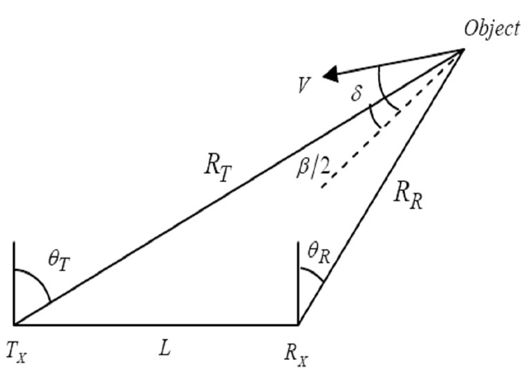
Figure 1. The geometry of a bistatic radar.
where  and
and  show the location of transmitter and receiver, and
  is the distance between these two sites .
 and
and  refer to the transmitter to target and the target to receiver ranges, respectively.
  is the bistatic angle,
  is the target velocity and
  is the velocity aspect angle. The transmitter, receiver and object are all located in a plane that called bistatic plane [6, 8,15,22].
2.1. Equation of Power
If a narrow band wave with power of  is sent by the transmitter, after scattering from the object, the received power of each receiver,
  , can be determined using Friis’ Formula [8].
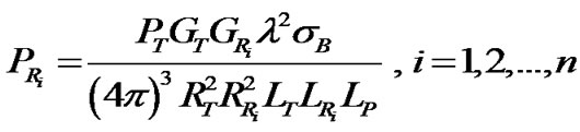 (1)
(1)
In Equation (1), n, λ and  are the number of receivers, the wavelength and the average propagation loss, respectively.
  and
and  refer to the gain of transmitter and gains of each receiver antennas.
  and
and  are transmitting and receiving system losses.
  refers to the RCS of the object. In a practical case,
 ,
,  ,
, ,
, ,
, ,
, ,
, can be measured, therefore, the RCS of the object,
  , can be obtained from Equation (1).
2.2. Estimation of Target Location
To estimate the location of a target in bistatic radars, receivers measure the time interval,  , between transmitted pulses and received echo waves, scattering from a target. Hence, the range sum,
  , can be calculated using the following equation.
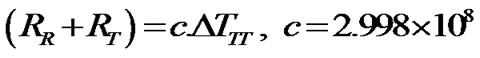 (2)
(2)
In each bistatic plane,  ,
,  and
and  can be obtained using the range sum and either
  or
or  (shown in Figure 1). If
  is known,
  ,
,  and
and  can be calculated from Equations (3–5) [7,8,9].
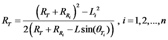 (3)
(3)
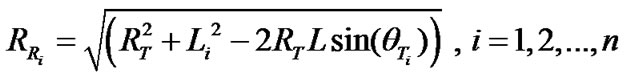 (4)
(4)
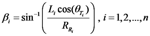 (5)
(5)
Having transmitter and receiver locations
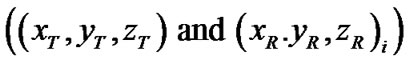
as well as  and
and  that obtained from Equations (3, 4), the location of object
  can be calculated in Cartesian coordinate system by solving Equations (6,7).
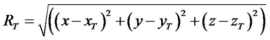 (6)
(6)
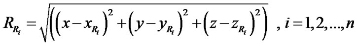 (7)
(7)
2.3. Computation of Target Velocity
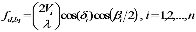
To estimate the velocity of target, the equation of “Doppler effect” is used [15].
 (8)
(8)
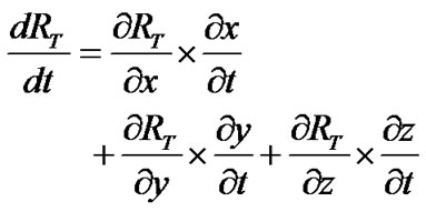
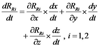
Also, the rate of change of transmitter and receiver ranges with respect to time is given by
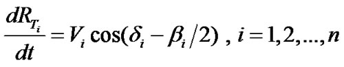 (9)
(9)
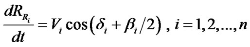 (10)
(10)
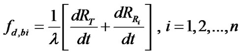
combining Equations (9,10) yields
 (11)
(11)
where  is the number of receivers. In this research work
  is set to 2. Having
  and
and  as well as
 the partial derivatives of
  and
and  with respect to time,
  ,
,  and
and , can be obtained from Equations (12,13).
 (12)
(12)
 (13)
(13)
2.4. Calculation of RCS
There are several analytical methods to calculate the
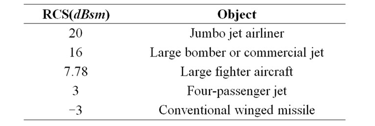
Table 1. Values of RCS for some typical objects [21].
RCS, such as those given in [23] and [24], which calculate the RCS of a cone and a missile. The RCS of typical objects can be found in text books [3,21,25] and some of them are shown in Table 1 [21].
3. Results
The multistatic radar system described in this paper consists of one transmitter and two receivers. To obtain the location and velocity of an object, the transmitter radar sends wave pulses with a specific period and then the receiver radars receive some pulses. In general, the pulses coming to receivers can consist of two parts. The first part is the pulses received from the transmitter directly. The second part is the scattered waves coming from an object, if there is any. First, the range sum, RRi+RT is calculated from Equation (2). Then, RT, RR, β, dRT /dt, dRR /dt in each bistatic plane are calculated using the parameters given in Table 2.
Next, combining Equations (3,4) and (6,7) the object location is estimated in 3D. Finally, combining Equations (9,10) and (12,13) the velocity of the target is computed.
Based on the above-mentioned simulation procedure, a MATLAB code was developed. Running this program, the velocity of the object, RT, RR1 and RR2 are given by 321.71m/s, 63.06km, 90.9km and 68.57km, respectively. The location of the object is estimated at (-30, 30, 46.6) km. Figure 2 and 3 show the system geometry and the polar plot of the location of the object.
The required parameters to determine the RCS of the object are shown in Table 3. Using Equation (1) along with these parameters, result in a RCS of 7.78dBsm. According to Table 1, this amount of RCS indicates that the object is a large fighter aircraft [21].
Also, the path of the aircraft obtained by tracking the object is shown in Figure 4.
4. Conclusions
Considering the advantages of multistatic radar systems in comparison with monostatic and bistatic ones, a multistatic radar system having one transmitter and two receivers was simulated. The simulation was able to calculate the location and velocity of an object in 3D. More importantly, by computing the RCS, it determined what
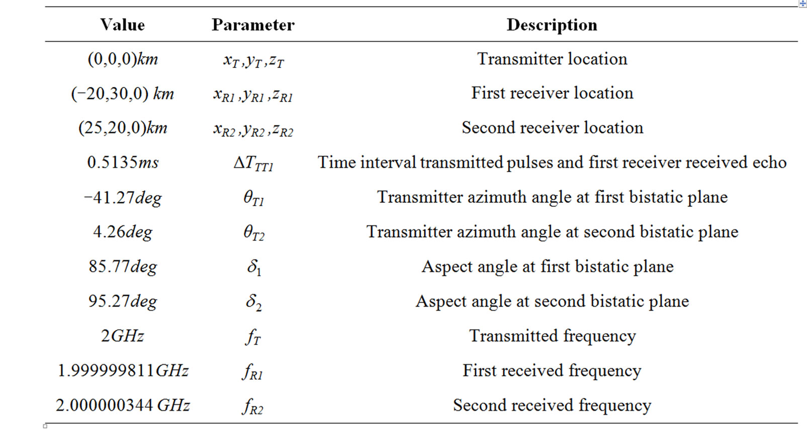
Table 2. Required parameters to estimate the location and velocity of an object.

Table 3. Required parameters to determine
the RCS of an object.
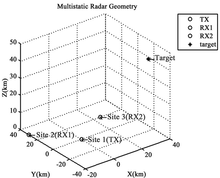
Figure 2. The system geometry.
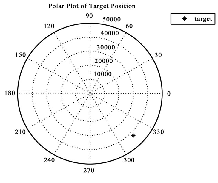
Figure 3. The polar plot of the location of the object.
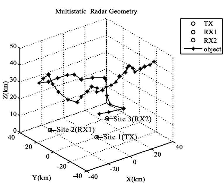
Figure 4. The path of the aircraft.
kind of object was flying in the surveillance area. In addition, the path of the object was estimated by tracking the object. As an application, this radar system can be applied to anti-air defense, anti-missile defense, ship’s navigation and traffic control systems.
In this paper only two receivers were considered. To widen the surveillance area, the number of receivers can be increased. However, in any detection only two receivers, which receive maximum power, are selected. This will be studied in our future work.
5. References
[1] “IEEE standard radar definitions,” IEEE, 2008.
[2] L. S. Kalantari, “Simulation of multistatic radar systems,” Master Thesis, The University of Sistan and Baluchestan, Zahedan, Iran, 2009.
[3] R. S. A. R. Abdullah and A. Ismail, “Forward scattering radar current and future application,” International Journal of Engineering and Technology, Vol. 3, pp. 61–67, 2006.
[4] M. I. Skolnik, Introduction to Radar Systems, 3rd Edition, McGraw-Hill, New York, 2001.
[5] M. I. Skolnik, Radar Hand Book, McGraw-Hill, New York, 1970.
[6] E. Paolini, A. Giorgetti, M. Chiani, R. Minutolo, and M. Montanari, “Localization capability of cooperative anti-intruder radar systems,” EURASIP Journal on Advances in Signal Processing, Vol. 2008, pp. 15, 2008.
[7] C. Wei and W. Chang, “System level investigations of television based bistatic radar,” Master Thesis, Cape Town, pp. 107, 2005.
[8] N. J. Willis, Bistatic Radar, 2nd Edition, Artech House, 1995.
[9] M. I. Skolnik, Radar Hand Book, 2nd Edition, McGraw-Hill, New York, 1990.
[10] J. Byrnes and G. Ostheimer, Advances in Sensing with Security Applications, Ciocco, Springer, Italy, 2005.
[11] W. Wang, “Application of near-space passive radar for homeland security,” Sensing and Imaging: An International Journal, Vol. 8, pp. 39–52, 2007.
[12] H. D. Griffiths and C. J. Baker, “Fundamentals of tomography and radar,” NATO Advanced Study Institute Advances in Sensing with Security Applications, 2005.
[13] P. Withington, H. Fluhler, and S. Nag, “Enhancing homeland security with advanced UWB sensors,” IEEE Microwave Magazine, Vol. 4, pp. 55–58, 2003.
[14] C. L. Teo, “Bistatic radar system analysis and software development,” Master Thesis, Naval Postgraduate School, Monterey, California, pp. 116, 2003.
[15] T. Johnsen and K. E. Olsen, “Biand multistatic radar,” Advanced Radar Signal and Data Processing, pp. 4.1– 4.34, 2006.
[16] T. Johnsen, B. Hafskjold, and K. E. Olsen, “Tracking and data fusion in Biand multistatic radar,” IEEE Radar Conference, Arlington, USA, 2005.
[17] A. Farina, “Tracking function in bistatic and multistatic radar systems,” IEE Proceedings F, 1986.
[18] W. Chongyu, X. Shanjia, and W. Dongjin, “Analysis of target tracking based on range difference measurement of multistatic radar system,” Journal of Electronics, Vol. 17, 2000.
[19] G. L. Soares, A. Arnold-Bos, L. Jaulin, C. A. Maia, and J. A. Vasconcelos, “An interval-based target tracking approach for range-only multistatic radar,” IEEE Transactions on Magnetics, 2008.
[20] T. E. Derham, S. Doughty, K. Woodbridge, and C. J. Baker, “Design and evaluation of a low-cost multistatic netted radar system,” IET Radar Sonar Navigation, Vol. 1, 2007.
[21] C. A.Balanis, Antenna Theory: Analysis and Design, 3rd Edition, John Wiley and Sons, New York, 2005.
[22] B. R. Mahafza, Radar Systems Analysis and Design Using Matlab, 2nd Edition, Chapman & Hall, 2005.
[23] T. Mosayyebi-Dorcheh, L. S. Kalantari, S. Mohanna, and S. Tavakoli, “Electromagnetic scattering from an infinite dielectric cone,” Progress in Electromagnetics Research Symposium, Russia, 2009.
[24] L. S. Kalantari, T. Mosayyebi-Dorcheh, S. Mohanna, and S. Tavakoli, “Missile radar cross section calculation and its use in 3-D anti-missile defense system,” Progress in Electromagnetics Research Symposium, Russia, 2009.
[25] W. Wiesbeck, Radar System Engineering, 13th Edition, 2007.