Journal of Water Resource and Protection
Vol.08 No.04(2016), Article ID:65734,10 pages
10.4236/jwarp.2016.84038
Development of a Portable Electro-Mechanical Educational Model for Variable Rate Center Pivot Irrigation Technology
Young J. Han1, Ahmad Khalilian2*, Jose Payero2, Nicholas Rogers1
1Department of Agricultural and Environmental Sciences, Clemson University, Clemson, SC, USA
2Edisto Research and Education Center, Department of Agricultural and Environmental Sciences, Clemson University, Blackville, SC, USA

Copyright © 2016 by authors and Scientific Research Publishing Inc.
This work is licensed under the Creative Commons Attribution International License (CC BY).
http://creativecommons.org/licenses/by/4.0/


Received 17 March 2016; accepted 18 April 2016; published 21 April 2016
ABSTRACT
Center pivot irrigation systems usually apply a relatively uniform amount of water to fields that are often inherently variable, which could lead to significant waste of water and energy. To address this issue, our team is now developing an Intelligent Center Pivot (ICP) by integrating sensor-based irrigation scheduling with variable rate irrigation technology. However, before this technology can be applied in commercial production, it is necessary to educate growers about its practicality and potential benefits. The objective of this study was to develop a portable tabletop intelligent center pivot model (ICPDemo) to demonstrate and promote adoption of the ICP technology. This paper describes an ICPDemo constructed in 2014, including the design specifications, electro-mechanical design, control strategy, and performance. The ICPDemo has performed according to design specifications and is successfully being used to demonstrate the benefits and effectiveness of ICP technology for irrigation scheduling.
Keywords:
Irrigation, Center Pivot Irrigation, Electro-Mechanical Model, Sensors, Control, Variable Rate Irrigation

1. Introduction
Center pivot irrigation systems are predominantly designed to apply a relatively uniform amount of water to fields that are often inherently variable due to factors such as different soil types, topography, or multiple crops. This field variability can result in significant waste of water and energy, runoff, chemical leaching, and reductions in yields and farm profits. Variable-rate irrigation has the potential to improve the efficiency of water and energy use as well as crop yields. Variable rate center pivots have been studied by [1] and [2] for their advantages compared with single rate irrigation systems. Over the last decade, the Precision Farming Team at Clemson University has developed a variable-rate lateral move irrigation system that has been successfully deployed by growers in commercial production in South Carolina [3] - [5] . However, since center pivot irrigation is the predominant irrigation method for row crop production in South Carolina, there is a need to refine the technologies developed for the lateral irrigation system to include center pivot irrigation systems [6] and [7] . Therefore, current efforts are being directed towards developing an Intelligent Center Pivot (ICP), which will integrate sensor-based irrigation scheduling with variable rate irrigation technology.
In order to reduce waste of water and nutrients and improve crop yields through this technology, there has to be an understanding among potential users about the technical aspects and potential cost/benefits of this technology. In the past, electro-mechanical models have been used successfully to demonstrate irrigation technology. For example, in 2010, our research team at Clemson University developed a portable electro-mechanical model to demonstrate nozzle pulsing technology for variable-rate lateral irrigation systems. Also, about the same time, researchers at the University of Georgia [8] developed a table-top variable-rate center pivot model to demonstrate nozzle pulsing technology. Both of these systems were successfully used in a variety of irrigation extension activities for several years, but they only focused on demonstrating VRI technology specially on nozzle pulsing technology. Now, since the technology has advanced, there is a need to demonstrated integration of sensor-based irrigation scheduling with VRI technology. Currently, there is no published information related to development and use of this type of models for irrigation demonstration.
A portable electro-mechanical model to effectively demonstrate the concepts of the intelligent center pivot technology to farmers, especially in indoor settings such as trade shows and farmer’s meetings, is currently not available. Therefore, the objective of this study was to develop a portable tabletop intelligent center pivot demonstration model (ICPDemo) that could be used to demonstrate and promote adoption of the ICP technology among growers. This paper describes the design and construction of the ICPDemo, including the design specifications, electro-mechanical design, control strategy, and performance.
2. Methodology
2.1. Design Specifications
The final product should comply with the following specifications:
・ Be a fully functional tabletop model of an ICP, which integrates variable rate irrigation system and irrigation scheduling.
・ Be less than 82 cm wide in order to be portable and easily fit through a standard door. This would affect: the size of the pivot boom itself (considering length and therefore relative height), the type of irrigation nozzle to allow for the proper throw of water, the size of the pumps to allow for adequate water flow, and the size and design of a reservoir (tank) to hold the water.
・ Have at least four management zones plus an end gun whose application rates can be individually controlled over a number of control sections in the field.
・ Have a working pump and irrigation nozzles across different management zones whose application rates can be individually controlled according to an irrigation rate map.
・ Have an electronic controller with enough controllable input/output channels and enough electrical current capacity to run pumps and motors.
・ Have a functional irrigation system with site-specific variable-rate control technology similar to those used in modern precision agriculture.
・ Have a rotational pivot speed that can be automatically controlled according to the irrigation rate map. The total run time should be approximately one minute from one end to the other in order to allow for adequate time to demonstrate each management zone.
・ Be a foolproof turn-key system that is simple and robust, so that anyone with little training can operate it without consulting a manual.
2.2. Electro-Mechanical Design and Construction
The final design was a small two-section center pivot covering a semi-circular area (Figure 1). The multi-view engineering drawings (front, side, and top views) of the system, including dimensions, are shown in Figures 2-4. The ICPDemo was constructed using 38 mm aluminum tubing for the boom and supports. The design also included a tabletop map with several management zones and different field features, such as various soil types and a standing pond. During construction, five 6.4 mm flexible tubes were routed through the boom from the pumps to the nozzles. This provided water flow to each section of the boom. The pivot was designed to rotate using two small reversible motors (5-rpm, 12VDC). One motor had enough torque to run the pivot, but the second one was added for redundancy. The motor shafts were attached directly to the pivot wheels (10-cmdiameter), which were taken off a small toy tractor. The size of the driving wheel and the rotation speed of the motor were chosen to achieve the total run time of approximately one minute from one end to the other end of the tabletop (0 - 140 degrees of rotation). A manual motor-override switch was installed to stop the system, in case more time for explanation was needed during any demonstration. A main power switch for the whole model and an individual pump override switch for each section of the pivot were also installed.
A total of five small 12VDC pumps, often found in automobile windshield cleaning systems (ACI Windshield Washer Pump, Advance Auto #172435), were used. Four of the pumps were used to control each of the four

Figure 1. Final design of intelligent center pivot demonstration model (ICPDemo).

Figure 2. ICPDemo―front view.
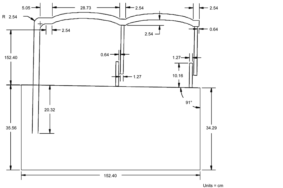
Figure 3. ICPDemo―side view.
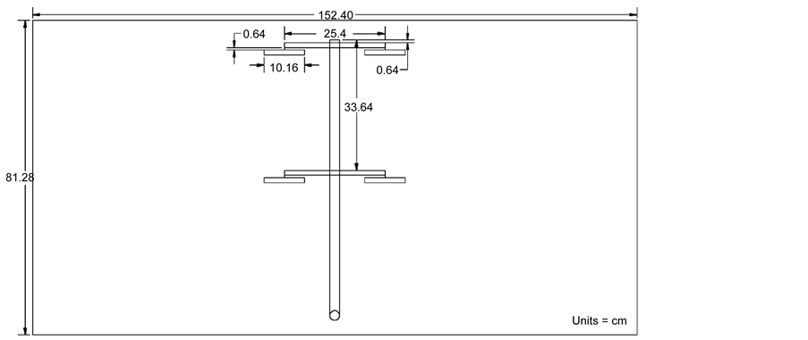
Figure 4. ICPDemo―top view.
management zones (2 nozzles per zone), with the fifth pump controlling the end gun. A separate pump was needed for each management zone, in order to control the irrigation rate based on the water requirement of that particular zone. These pumps could be turned on and off to demonstrate the nozzle pulsing technique. Water was stored in a reservoir constructed from clear LEXANTM sheets joint together with LEXANTM cement. This reservoir also allowed for secure mounting of all the pumps (Figure 5).
The main control box under the ICPDemo was constructed from wooden boards (5 × 10 cm), plywood, and paneling. This box housed the water reservoir, 12V power supply (Pyramid #PSV300), relays, controllers and all wiring. The top of the box was angled on two planes to allow all water applied to drain to one corner. In this corner a hole was cut in the top of the box and a funnel was placed inside to allow all water to drain back into
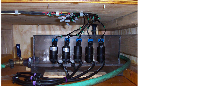
Figure 5. Water reservoir with mounted pumps.
the reservoir to be recirculated. A 25-mm ID flange bearing (Peer Bearings, HCFTS205-16) was mounted to the underside of the top of the box to allow the pivot to rotate with reduced friction. The simulated field map was laminated and placed on top of the box and a piece of clear LEXANTM sheet was also attached on top of the map to cover the full length and width of the box. The top of the box was surrounded by 25-mm walls made of the LEXANTM sheet around the perimeter to ensure all water recirculated properly.
A Programmable Logic Controller (PLC) (Crouzet Automation Model CD-20, Coppell, TX) was used to control the five pumps and the reversible motor. The PLC had 12 inputs and 8 outputs and operated on 12VDC power supply. A PC-based data acquisition and control system was considered, but the PLC was chosen for its simplicity and versatility. Anyone with little training can operate the PLC by simply turning on a switch, without waiting for a PC to boot up and load specialized software.
The full scale VRI pivot normally utilizes a Global Positioning System (GPS) receiver, to locate the position of the pivot within the field for zone management. Therefore, to simulate a GPS, a small Light Emitting Diode (LED, RadioShack, 276-024) was mounted to the end of the irrigation boom and was turned on and off at 1 Hz. Since a GPS receiver would not properly operate indoors, three watertight micro switches (Honeywell Sensing and Control #V15W11-WZ200A06-AW1, Morristown, NJ) were used instead to locate the position of the pivot within the simulated field. The PLC interpreted the output of the micros witches using binary code (open or closed translating to 0 or 1) to provide location information at any given time. For example, the output binary code of “101” indicated that the pivot was in section 5 (Figure 6). A small switch plate with ridges and grooves was constructed to allow the micro switches to open or close at the appropriate times to correspond with each management zone (Figure 6).
Figure 7 shows the wiring schematic of the PLC. The five water pumps (indicated as “P”) were wired into the first five outputs channels (01 to 05). The first four pumps controlled one management zone each, and the fifth pump operated the end gun. Two relays connected to the next two outputs controlled the drive system for the pivot. The first relay (T92S11D22-12, Potter & Brumfield) simply turned the drive system motor (M) on or off with any specified duty cycle. This enabled the travel speed of the pivot to be controlled precisely as needed by a pulse-width modulation technique. The second relay (KUHP-11D51-12, Potter & Brumfield) controlled the polarity of the 12 volts DC motor (M) to reverse the travel direction of the ICPDemo when needed. The last output of the PLC controlled the blinking of the LED that simulated a GPS receiver. The ICPDemo was fully tested to assure that all design specifications were met.
2.3. Control Strategy
The ICPDemo had several management zones and field features, such as various soil types, to simulate actual condition of the commercial production fields in southeast USA. These features and management zones programmed on the final model can be seen in Figure 8. However, the program can be changed to simulate other conditions. In the example of Figure 8, the four management zones are numbered Z1 through Z4. The area outside Z4 is to be irrigated by an end gun. The field is divided into eight sections, starting from Section 0 on the
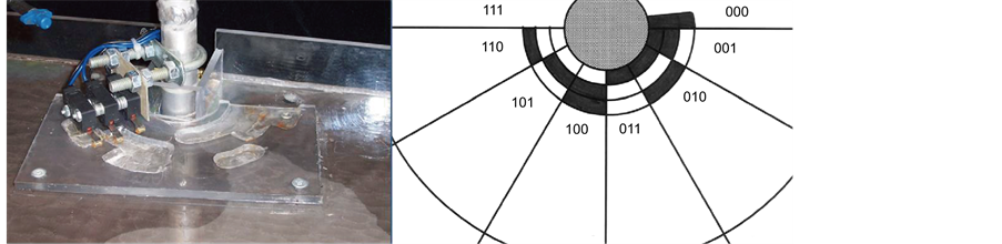
Figure 6. The switch plate with ridges and grooves (left), and output binary codes for each zone (right).

Figure 7. PLC wiring diagram (P = pump; M = motor: T92S11D22-12 and KUHP-11D51-12 = relays; GPS = LED to simulate GPS; and Pos1, 2, 3 = position switches).

Figure 8. Management zones and soil features.
left at the 0 degree position, and numbered clockwise to the right up to Section 7. The middle six sections (S1-S6) are irrigated according to an irrigation rate map. Sections 0 and 7 are used as a turning area for the pivot to turn around by reversing the polarity of the driving motors. Management Zones and Soil Features in Figure 8 were designed to encompass several different field attributes in order to demonstrate various functions of a Variable Rate Intelligent Center Pivot. In this example, the clay soil received the irrigation rate that the ICPDemo could deliver at full travel speed without pulsing nozzles (1X in Table 1). For the dry sandy soil, the irrigation rate was doubled (2X) by reducing the travel speed to 50%. For the boggy areas, irrigation rate was reduced to 50% of the clay soil (0.5X) by pulsing nozzles.
Table 1 shows the irrigation strategy for each zone through different sections for the given field features. The irrigation rate was controlled by changing the pivot travel speed and/or by pulsing the nozzles. For example, in the first section (S1) where all zones had clay soil type, all four zones would receive the same irrigation application rate (1X), which could be accomplished by running the pivot at full travel speed without pulsing the nozzles. However, in the second section (S2) where the first three zones had sandy soil, the nozzles in Zones 1 through 3 would apply 2X irrigation rate by reducing the travel speed to 50% without pulsing the nozzles. But, to apply the 1X rate to the clay soil in Zone 4, the nozzles would be pulsed with 50% duty cycle. The irrigation strategy would also reduce the application rate to 50% (0.5X) for the boggy areas by pulsing the nozzles at 50% duty cycle. The system would also avoid irrigating the pond and turning areas by turning the pumps off (0X). It would also turn the end gun off in Sections 4 through 6 where a roadway passes outside the sections. For the variable rate irrigation, duty cycles for any management zones or forward speed could be set to any value between 0 and 100% in the control program.
Figure 9 shows schematic of the PLC program written to achieve the irrigation strategy illustrated in Table 1. The program uses a series of logic gates (NOT, AND, and OR gates) to control pumps and the drive system. A series of inverters (NOT gates) and four-input AND gates on the left analyzed three input switches to find out which of the eight sections the center pivot was in. Since the output of an AND gate was 1 (on) only when all inputs were 1, inverters were used whenever input values were 0 (off). For example, if all three switches were in the off position, the last AND gate would be turned on to signify that the pivot was in Section 0 (000). If the third switch was on, the output of the first AND gate would be on to signify that the pivot was in Section 1 (001).

Table 1. Example irrigation rates for the simulated conditions in Figure 7 (CW = clockwise; CCW = counter clockwise; X = irrigation rate for the clay soil).

Figure 9. Schematic of the PLC program used to implement the irrigation strategy in Table 1.
If all three switches were on, the output of the AND gate for section 7 (111) would be on.
Five six-input OR gates on the rightmost side controlled the nozzles in four zones and the end gun. The six inputs on each OR gate were connected to position signals from Sections 1 through 6, respectively. All nozzles were off in Sections 0 and 7 which were used as a turning area. Since the output of an OR gate was 1 (on) if any of the inputs were 1, any position between Sections 1 and 6 could turn on the nozzles. If a nozzle was to be pulsed with a 50% duty cycle in a section, the input signal from that section would pass through a Li Timer with a 0.5 sec On-time and a 0.5 sec Off-time. The duty cycle of any nozzles could be changed by adjusting On-time and Off-time of the individual Li Timers. Missing inputs on any OR gates mean that the nozzle will not operate in the sections from where input connection was missing. In an actual VRI system, the nozzle pulsing time is normally one minute. However, due to the small size of the model and time limitation for demonstration, one second cycle was used instead.
The two four-input OR gates on the lower-right side controlled the motors in eight sections. The motors were mostly run at 100% speed except in Sections 2 and 3 (50% travel speed), where Li Timers were used to pulse the motors on or off with a 50% duty cycle. The duty cycle of the motors could be changed by adjusting On-time and Off-time of the Li Timers.
When the pivot reached Section 0 (leftmost) or Section 7 (rightmost), the position signal would set the Reversing Relay on or off to change the rotational direction of the ICPDemo to clockwise at Section 0 and counterclockwise at Section 7. There was a delay of 1.5 seconds before the motor changed its direction to confirm that the pivot actually was in Section 0 or Section 7. This time delay prevented the accidental direction change in any other sections due to a momentary false reading from the switches. This delay time interval could be changed during runtime from Parameters Menu on the PLC Screen. The LED simulating a GPS receiver was connected to the last output of the PLC and was programmed to blink at 1 Hz.
3. Results and Discussion
A fully functional tabletop model of an intelligent center pivot was constructed according to the design specifications and was programmed using an example irrigation control strategy on a PLC. The system demonstrated varying application rates over sand, clay, a low-lying boggy area, a pond, and other features around the simulated field. The varying application rates were achieved by either pulsing the motors to reduce travel speed and apply a higher rate, pulsing the pumps to reduce the application rate, or turning the pumps off to avoid irrigation.
During the design and testing process, the durability of the pumps was found to be inadequate. The automobile windshield washer pumps used in this model were not designed to operate continuously, and could overheat if used continuously. This problem could be solved by replacing these pumps with models designed for continuous operation such as those normally used with small water fountains. However, due to short demonstration period, there was no need for continuous operation. Also, the two-planed drain system for the recirculation of water was not quite adequate, due to the surface tension of water clinging to the LEXANTM sheet on the top of the model. A greater slope was needed to achieve a full drain. For this model a squeegee was used to direct the residual water to the drain.
The final ICPDemo model has been successfully demonstrated in a number of presentations to various clienteles. This model could also be used as a teaching aid in a classroom for current and future students. It is our intention to continue to use this model in future irrigation extension activities such as field days, workshops, growers’ production meetings, and in service training for county extension agents.
4. Conclusion
A tabletop intelligent center pivot demonstration model (ICPDemo) was designed and constructed to demonstrate and promote adoption of the innovative ICP technology. The final design was a small two-section center pivot covering a semi-circular field. The ICPDemo had four management zones plus an end gun whose application rates could be individually controlled over a number of control sections in the simulated field. The rotation speed of the pivot could also be controlled according to a simulated irrigation rate map. To demonstrate the variable nature of the ICP irrigation system, various soil types and field features were incorporated in the management zones, and the irrigation control strategy was programmed on a PLC. The ICPDemo is being used to showcase the ICP technology during a variety of irrigation extension activities.
Acknowledgements
This material is based upon work supported by NIFA/USDA, under project number SC-1700442, Technical Contribution No. 6390 of the Clemson University Experiment Station.
Cite this paper
Young J. Han,Ahmad Khalilian,Jose Payero,Nicholas Rogers, (2016) Development of a Portable Electro-Mechanical Educational Model for Variable Rate Center Pivot Irrigation Technology. Journal of Water Resource and Protection,08,449-458. doi: 10.4236/jwarp.2016.84038
References
- 1. Evans, G.W. and Harting, G.B. (1999) Precision Irrigation with Center Pivot Systems on Potatoes. Proceedings of ASCE 1999 International Water Resources Engineering Conference, Seattle, 8-11 August 1999, American Society of Civil Engineers, Reston.
- 2. Perry, C., Pocknee, S. and Hansen, O. (2003) A Variable Rate Pivot Irrigation Control System. In: Stafford, J. and Werner, A., Eds., ECPA 2003, Proceedings of the Fourth European Conference on Precision Agriculture, Wagner Academic Publishers, 539-544.
- 3. Khalilian, A., Henderson, W., Han, Y., Owino, T. and Niyazi, B. (2007) Scheduling Site-Specific Irrigation for Cotton Production Using a Linear Move System. Proceedings of the Beltwide Cotton Conferences, New Orleans, January 2007, National Cotton Council of America, Memphis, 883-888.
- 4. Khalilian, A., Han, Y.J. and Farahani. H.J. (2008) Site-Specific Irrigation Management. In: Eidson, G.W. and Sawyer, C.B., Eds., Proceedings of 2008 South Carolina Water Resources Conference, Charleston, 14-15 October 2008.
- 5. Han, Y.J., Khalilian, A., Owino, T.O., Farahani, H.J. and Moore, S. (2009) Development of Clemson Lateral Variable-Rate Irrigation System. Computers and Electronics in Agriculture, 68, 108-113.
http://dx.doi.org/10.1016/j.compag.2009.05.002 - 6. Khalilian, A., Han, Y., Barnes, E.M. and Henderson, W. (2012) Water Use Efficiency of Different Cotton Cultivars. Proceedings of the Beltwide Cotton Conferences, 3-6 January 2012, Orlando, National Cotton Council of America, Memphis, 517-521.
- 7. Khalilian, A., Qiao, X., Farahani, H., Han, Y. and Payero, J. (2013) Parameterization of the FAO AquaCrop Model for Irrigated Cotton in the Humid Southeast U.S.A. Proceedings of the Beltwide Cotton Conferences, San Antonio, 7-10 January 2013, National Cotton Council of America, Memphis, 522-527.
- 8. Perry, C. (2010) Personal Communication.
NOTES

*Corresponding author.