Journal of Software Engineering and Applications
Vol.09 No.03(2016), Article ID:65292,11 pages
10.4236/jsea.2016.93008
Analysis of Recent Secure Scan Test Techniques
Cheng Xing1, Sungju Park2, Ji Zhao1
1Institute of International Finance and Banking University of Science and Technology Liaoning, Anshan, China
2Department of Computer Science & Engineering, Hanyang University, Seoul, Korea

Copyright © 2016 by authors and Scientific Research Publishing Inc.
This work is licensed under the Creative Commons Attribution International License (CC BY).
http://creativecommons.org/licenses/by/4.0/


Received 4 February 2016; accepted 28 March 2016; published 31 March 2016
ABSTRACT
Side channel attack may result in user key leakage as scan test techniques are applied for cryptographic chips. Many secure scan designs have been proposed to protect the user key. This paper meticulously selects three current scan test techniques, analyses their advantages and disadvantages and also compares them in security and area overhead. Users can choose one of them according to the requirements and further combination can be implemented to achieve better performance.
Keywords:
Side Channel Attack, Scan Test Techniques, Secure Scan Designs

1. Introduction
1.1. Problem Statement
Scan chain-based Design for Testability (DFT) has been the most popular testing technique due to the high fault coverage and low hardware overhead. Nevertheless, for cryptographic IP cores such as Advanced Encryption Standard (AES), Data Encryption Standard (DES) and Triple DES (TDRE), which is key-based algorithm, it is vulnerable to the side-channel attacks (SCA). Since the flip-flops in a scan chain can be accessed and analyzed, secret key can be retrieved and confidential information can be leaked [1] . The secure scan which maintains high testability without compromising the security is required to crypto cores.
Some methods have been proposed to protect the user key from side-channel attack, described as follows. Mirror key register (MKR) is inserted to the AES core so that the user key cannot be loaded in scan test mode. Paul et al. [2] proposed to reorder the scan chain cells by scrambling them and only an authorized user can get the correct order. In [3] , inverters are inserted to scan chains to make it difficult for attackers to discover the internal scan structure and its upgraded version is [4] . Nevertheless, most of these traditional secure DFT techniques try to protect the key within the core and modify the structure of scan chain, the security of the primary inputs and outputs of SoCs is ignored. It can lead to a potential attack via insecure test wrapper [5] .
1.2. Advanced Encryption Standard
AES has been accepted as a standard for symmetric encryption by the National Institute of Standards and Technology (NIST) since 2001 [6] . The AES algorithm is a symmetric block cipher that can encrypt and decrypt information. The AES algorithm is capable of using same cryptographic keys of 128, 192 and 256 bits to encrypt and decrypt data in blocks of 128 bits. The basic unit for processing in the AES algorithm is byte. Input, output and secret key bit sequences are internally processed on a two-dimensional array of bytes called state, which consists of four rows of four bytes.
After an initial round key addition, the algorithm is executed by implementing a round function as shown in Figure 1. The plaintext is first copied to the state array and then xored with the secret key. The state array is transformed by implementing a round function that is repeated 10 times. The final state is then copied to the output. The round function is parameterized using a Key Expansion function to generate a variation of the original secret key for each round. One AES round has SubBytes, ShiftRows, Mix Columns, and Add Round Key four operations. After the first round, the value is stored in a round-register, and the value of the round-register is fed back as input of next round. In order to test the chip, the round-register must be included in the scan chain. As a consequence, attacker can use the controllability and observability of scan chain to retrieve the secret key.
1.3. Attack Methods
1.3.1. Scan-Based Attack
In cryptography, a side channel attack (SCA) is any attack based on information gained from the physical implementation of a cryptosystem, rather than brute force or theoretical weaknesses in the algorithms. For crypto chips, the general principle of the scan attacks consists in observing the data stored in the round-register after the execution of the first round for several known plaintexts by means of scan-out operations, then from the observations to derive the secret key [7] . For AES core, scan-based attacks utilize the controllability and observability of scan DFT methods to retrieve the user key. The concrete methods can be list in two steps: determine scan- chain structure and recovering round key.
The intermediate cipher-text after the pre-round and first round is stored in the round register.
Although the register is included in the scan chain, the attacker does not know which bits in the bit stream are from the round register. By switching the AES circuit between normal mode and test mode, the structure can be determined.
In the architecture shown in Figure 2, pre-round and round 1 are performed in 1 cycle and two round keys, RK0 and RK1 are used. We will apply a chosen plaintext byte at a1,1 and observe the corresponding word in round register. We will then infer the value b1,1 at and determine the round key byte RKO1,1. We will determine all bytes in the round key RK0 by repeating this step
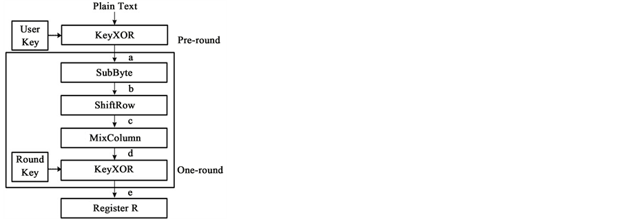
Figure 1. Process of AES encryption.

Figure 2. Scan-based attack to AES core.
1.3.2. Potential Attack via Wrapper
This potential attack via insecure test wrapper attack is illustrated in Figure 3 [5] . During critical system operations, important data (such as AES encryption keys) are transferred from memory to the AES core via primary inputs or outputs. Those important data, when captured by the test wrappers, may be shifted out and observed in boundary scan mode. The original IEEE 1500 test wrapper does not provide any security protection for PI/PO. It is therefore very important to have a secure test wrapper designed for critical IP cores, such as AES.
2. Three Secure Scan Techniques
Many traditional secure scan designs are introduced in chapter 1, most of these traditional secure DFT techniques only try to protect the key within the core or modify the structure of scan chains. However, the security of the primary inputs and outputs of SoCs is ignored. It can lead to a potential attack via insecure test wrapper. We focus on three secure DFT techniques in this work, which shows better performance and security in some aspects. This chapter introduces these three techniques in detail.
2.1. Fake Key Based Secure Scan Design
Fake key based secure scan technique is based on IEEE standard 1149.1 (JTAG). A new instruction “Secure Scan Test” is add to instruction decoder. It is invoked whenever the normal mode is changed to scan test mode. The architecture is illustrated in the Figure 4 from [9] . First the scan output is blocked by an AND gate with signal “Scan Output Gating Signal”. Unless the signal is changed to 1, the gated scan output will maintain at 0 so that the scan chain possibly including encrypted data can be shifted to flush out. Then during the normal scan test mode, fake key is loaded instead of user key into AES core by asserting the signal “Load Key” which is generated by the new instruction. Further a counter is inserted to tell the number of scan shifts to flush out the encrypted data.
The data remaining in the internal registers becomes the target of attackers whenever normal mode is changed to another mode. An instruction named “Secure Scan Test” newly added to JTAG standards is applied for scan testing. With the invocation of the instruction, initially the internal scan chains are shifted out to flush out the data without being observed by blocking scan output port. It is noted that secure mode is changed to insecure mode by power off the AES chip in which all the scan flip flops are assumed to have reset mode. Afterward the mode is changed to regular scan test mode with activating the scan output port, in which Fake key instead of the user key is loaded to the AES core. The Load Key signal from the instruction decoder is used to drive the Key values. The control block generating the Load Key and Scan Output Gating signals is shown in Figure 5, where the counter initially activated tells the number of scan shifts to flush out the encrypted data.
This technique preserves compatibility with IEEE 1149.1 standards. No modification is needed to the AES core thus the AES IP can be reused in designing a SoC. The secret user key is completely protected. The circuit implementation requires less design penalties such as area overhead, power consumption, and fault coverage.
2.2. Golden Key Based Secure Test Wrapper
Golden key based secure test wrapper technique is based on IEEE standard 1500. Its authentication mechanism

Figure 3. Security problem of a test wrapper.

Figure 4. Secured scan architecture by Fake Key insertion.

Figure 5. Modified JTAG TAP controller.
is utilized to lock and unlock the modified standard test wrapper. The architecture is illustrated in the Figure 6 from [5] , where the modified components are highlighted. Some specified wrapper boundary cells are modified to construct an on-chip LFSR path which generates a golden key. The inputs and outputs of scan chains are gated with “unlock” signal which is generated by the STW controller. Only if the test patterns are matched with generated golden key, the test wrapper is unlocked. The WIR is also modified to decode a new instruction “UNLOCK_STW” and to generate STW control signals.
The inputs and outputs of internal scan chains are gated by the unlock signal, which is generated by the controller. Both IWBR and OWBR are replaced by their secure versions, SIWBR and SOWBR, respectively. In addition to the original wrapper serial ports (WSP), an extra input Secure Enable is needed. The WIR is also slightly modified to decode one extra instruction. UNLOCK_STW, and generate STW control signals. Figure 7 shows the state diagram and output signals of the STW controller. When powered up, the STW controller is in the IDLE state.
When the InitLFSR signal is asserted, the LFSR is loaded with a predefined seed that generates the golden STWK. When StartController = 1, the controller enters the COMPARE state, in which the input bit stream from the WSI is compared with the golden STWK. After the comparison is done, if every bit of the input bit stream matches the golden STWK, the wrapper enters the UNLOCK state. The unlock signal rises to one in the UNLOCK state. The unlock signal rises to one in the UNLOCK state. If there is any mismatch during the key comparison, STW returns to the idle state without unlocking. Only after STW enters the UNLOCK state are the internal chains allowed to shift and wrapper boundary registers allowed to capture. When WRSTN = 0, the STW controller resets and then return to the IDLE state. Also a comparator and counter are needed in this design. In the COMPARE state, the golden STWK is generated by an on-chip LFSR. Longer LFSR provides better security with the cost of larger area to reduce the area overhead, the LFSR can be embedded in the wrapper boundary registers. Since some WBCs may have more than one flip-flop, the update flip-flops can serve as the LFSR before STW is unlocked. It is noted that not all wrapper scan cells are replaced by their secure version. The exact amount of replacement depends on the required security and the length of STWK. Figure 8 shows an implementation of SIWBC.
Compared with the original WBC, the SIWBC has one additional mux. When InitLFSR is asserted, the update flip-flop is initialized to either a one or zero, which is predetermined by the LFSR seed solver. When the LFSR is enabled, the LFSR path is connected from LFSRin to LFSRout through the update flip-flop. The other paths of the SIWBC remain unchanged. When CaptureSWR = 1, the function path is connected from WFI to WFO. When ShiftSWR = 1, the shift path is connected from WSI to WSO through the shift flip-flop. In total, five new control signals and two I/o signals are needed for this SIWBC.

Figure 6. Architecture of STW.
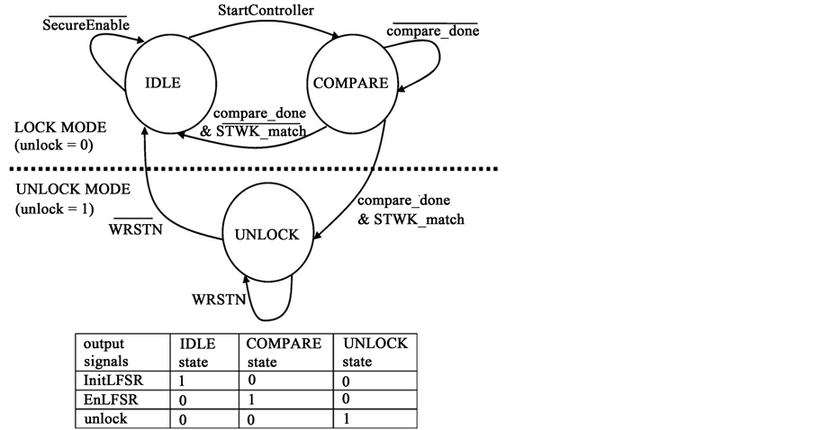
Figure 7. STW controller.
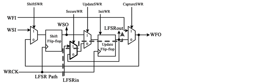
Figure 8. SIWBC.
This technique has the following advantages. First of all, STW is designed and implemented by SoC integrators so it provides security in the system level. Once a core is wrapped by STW, not even the original IP provider can attack the core, which increases the confidence of SoC costumers. Second, unlike other techniques which change the original circuit design, STW requires no modification in the original IP core. Third, STW is fully compatible with the IEEE 1500 standard. Finally, the STW key length can be easily extended using LFSR without extra area overhead.
2.3. KATAN Based Secure Test Wrapper
KATAN based secure test wrapper technique is also based on the standard test wrapper. A lightweight KATAN block cipher is used as the authentication mechanism to access the test wrapper. The architecture is illustrated in Figure 9 from [8] . KATAN can be implemented with software, on a secure sever, as well as with hardware. An on-chip true random number generator (TRNG) [7] is utilized to generate random number nonce as plaintext. KATAN software receives it via a serial interface. The plaintext is also transmitted to the on-chip KATAN hardware. KATAN software and hardware use the same key which is securely stored on sever and in an on-chip no-volatile memory. The cipher text generated by the software and the hardware are then evaluated in an on- chip comparator. If they match, then the test wrapper is unlocked by an “Unlock Wrapper” signal and enable normal scan test. The test protocol involved in the design is presented below. It can only be executed by the SoC

Figure 9. Design of the secure test architecture.
Integrator in possession of a valid key. The scan chains are otherwise locked against attacks by disabling the scan-in and scan-out.
This technique presented here preserves the existing structure of Standard Test Wrapper boundary cell. And is secure (does not use LFSRs or send the key in plaintext). It also uses standard scan chains for thorough testing of the crypto cores. In this manner, the current work seeks to address the tradeoff between security, testability and test area overhead. The design is highly scalable, as it does not affect the existing scan-chain DFT present within the SoC, and only adds some modules.
This access mechanism is necessary in order not to provide any side-channels which may leak secret information for attackers. However, this approach requires the authentication mechanism to be implemented in hardware incurring an area overhead, and the authentication secrets to be securely stored in non-volatile memory, which may be susceptible to side-channel-attacks. The author proposed a new method to enhance the secure test wrapper allowing testing of multiple IP blocks using a PUF-based authentication mechanism which overcomes the necessity of secure NVM and reduces the implementation overhead. The architecture is shown in Figure 10, comparing with the KATAN-based wrapper, only authentication part is replaced by a PUF-ECC module.
3. Analysis and Comparison
Three kinds of techniques in two types secure scan designs are analyzed and compared in this part. This work focuses on comparing them in four aspects, with some slight issues also mentioned.
3.1. Standard Related Issue
First of all, the standards related issue is analyzed and compared. The fake key technique in [9] is based on the IEEE std. 1149.1, while golden key technique [5] and KATAN technique [8] are based on IEEE std. 1500. The fake key technique modifies the standard instruction decoder by adding a new private instruction to choose between user key and fake key to be loaded during normal and test mode, respectively. There is no design change is needed to the internal logic of the AES core. As a consequence, this method is able to preserve compatibility with JTAG standard, to reuse predesigned AES IP, and to completely protect the user key with less design penalties such as area, power, and testability.
There is no modification required to IEEE 1500 standard in KATAN based technique, since it only use a challenge-response authentication to protect the entire wrapper and the core within the wrapper. By contrast, the golden key based technique modifies several components such as boundary registers, wrapper instruction register, and test wrapper controller. In compatibility aspect, neither of these two wrapper techniques change the crypto core so that they are compatible with their corresponding standards and the AES core also can be reused in designing in a SoC [9] .
To reduce the congestion of test control interface wiring of IEEE 1500 wrappers in SoCs, an IEEE 1149.1 tap

Figure 10. PUF-based secure test wrapper model.
controller is required and connected with the wrapper by using a glue logic block [10] . Consequently, the two secure wrapper techniques are also compatible with IEEE std. 1149.1. The standards related issue can be summarized in the Table 1.
3.2. Protection Mechanism
Protection mechanisms are analyzed and compared among the three techniques. The key idea of the [9] is loading fake key instead of user key during the test mode. Further meticulous care is taken by blocking the scan output using a signal generated by instruction decoder so that no scan output can be observed during the scan mode.
Both of the two secure test wrapper techniques adopt locking and unlocking authentication mechanism to protect the crypto core. In lock mode, AES core within the wrapper could not be able to access and test; while in unlock mode, test patterns can access to AES core through the scan chains, and responses can be scanned out. And both inputs and outputs of scan chains are gated by unlock signal, which is determined by a comparator. The difference is, the golden key based technique [5] uses an embedded LFSR as golden key and compare it with input bit stream, while the KATAN based technique [8] uses a light weight cipher algorithm both in hardware part (embedded on chip) and software part (test server), and compare their cipher texts after given the same input plaintext.
It would appear from the above that fake key only protects the user key by replacing it with a fake key, while the two secure wrapper techniques are able to protect the entire core.
3.3. Security Issue
Security issue is analyzed and compared in some aspects. For an attacker, all the attacks such as side channel attack [1] , and signature attack [11] are created only to obtain the secret key. Therefore the most effective secure method is to protect secret key. The fake key method [9] uses fake key instead of the user key in test mode to ensure the security of the user key. Some other protection measures are also applied for possible small leaks such as probable residual encrypted data. Even though a meticulous care is taken, primary inputs and outputs may supply attack channel if in SoC environment.
Secure scan wrappers liberate this issue by wrapping the whole core and locking it unless the identity of tester is authorized. In [5] , wrapper boundary register is modified by inserting an extra mux in some specified cells to generate a new LFSR path. The length of STWK (k) and degree of LFSR (d) are determined by the required security, and higher security produces more penalties. There are still three possible attack scenarios (as shown in the Table 2) in spite of the external and internal protection. First of all, if the hacker knows nothing about k or d, then he has to try exhaustively all bits sequences of lengths 1 to k. Security is defined as the reciprocal of the probability to unlock STW by random trial. Second, if the hacker knows k but not d, he has to try exhaustively all bit sequences of length k. The security of scenario two is equal to the number of all possible of length k. In the last scenarios, if the hacker knows both k and d, then his search space is slightly smaller than that of the second scenario. Table 1 summarizes the security of three scenarios. It is seen that STW provides good security

Table 1. Comparison of standard related.
Table 2. Security of STW.
for a reasonable number d. However, the reliability of LFSR seed leads doubt in [8] and [12] since non-ire- ducible polynomials of LFSR may be obtained by brute-force attack.
To solve the above-mentioned potential problem, KATAN based wrapper [8] adopts challenge-response structure rather than LFSR to verify the identity of tester. Chosen plaintext attack and replay attacks are not feasible as the plaintext is a Random Number nonce. The attacker can only eavesdrop on the serial communication taking place between secure chip and test server. Since the random number nonce is generated on-chip and sent serially to the server, while the cipher text on this nonce is generated by the server, it makes no sense to replay it back, as each time, a new nonce is generated by the TRNG. TRNG provides a truly random sequence of bits, as compared to pseudo-random obtained from LFSRs. LFSRs generate a predictable sequence of bits due to their linearity and it is possible to deduce the next sequence once the seed and feedback polynomial are known. Man-in-the-middle attack is feasible if the attacker has physical access to the chip so that attacker can eavesdrop on the serial communication-taking place between them. The probability of mounting successful attacks on this secure test structure is now stated briefly. The probability of collision in a Guessing attack is 2−32 if 32 bits is the block length (KATAN 32). Attacks on the block cipher have the same probability. Moreover, the security of the KATAN key may be susceptible since it requires additional non-volatile memory.
To overcome the above-mentioned problem, a physically unclonable functions (PUF) based method is proposed by the same author [13] . This method provides a secure test environment allowing only eligible testers to test the individual IP blocks in a SoC. The requirement of secure-key storage on NVM is overcome by using a Hamming distance-challenge based authentication mechanism using PUFs in order to prevent replay attacks.
3.4. Area Overhead
We implemented above-mentioned techniques on same benchmark with identical AES core. First of all, the boundary or wrapper boundary cells are compared. Fake key based technique uses a standard boundary scan cell (BSC) without any modification. Also KATAN based technique uses a standard wrapper boundary scan cell (WBC). Standard wrapper cell may have many kinds of structures, in order to compare properly between two secure test wrappers, golden key based method adopts a modified WBC based on the same structure with an extra mux. The result shows the IEEE 1149.1 BSC has the least area as compared to other two techniques.
The comparison of overhead is derived from the experiment results, which shown Table 3. From structure point of view, KATAN based technique may has the largest area since an on-chip KATAN cipher block seems
Table 3. Comparison of area.
larger than a LFSR key embedded in the boundary register. However, it is seen from the results of experiment, KATAN based authentication mechanism is smaller due to its light weight, only 32-bit cipher length. It is noticed that the length of LFSR key and KATAN can be changed according to the expected trade-off between cost and security. According to the results, golden key based technique [5] has the most area overhead, while the KATAN has the least area overhead.
3.5. Possible Improvement
Through the analysis, none of the techniques is unassailable. Although there are still some possible leaks in these advanced techniques to a certain degree, the advantages can be extracted and combined to generate a more perfect method under the circumstances.
Some burgeoning techniques can be used properly. The hardware random number generators are completely unpredictable, and the theory’s assertions of unpredictability are subject to experimental test. TRNGs provide a truly random sequence of bits, as compared to pseudo-randomness obtained from LFSR. TRNGs can be applied in the authentication mechanism, in order to make the crypto cores harder to attack.
Recently, increasing amounts of methods focus on the physically unclonable functions. PUFs are promising security primitives that exploit the physical characteristics of a device. PUFs can be used as secure key storage, and in authentication protocols. Since PUFs are based on the physical properties of the device in which they are embedded, no other entity can verify the response of a PUF to a given challenge without a priori knowledge of an authentic challenge response pair. As a consequence, PUF, with the feature of unpredictability, unclonability, tamper-resilient, and robustness, may become a trend in the field of secure test scan.
4. Conclusion
This thesis discusses three recent secure DFT techniques for crypto core. The three techniques are analyzed and compared in several aspects such as security, architecture, and area overhead. Both advantages and disadvantages are stated in the thesis. Some techniques have higher security; some techniques produce lower area overhead; some techniques show high-performance under SoC environment. To achieve the expected trade-off among testability, security and test cost, user can select the proper technique or the combination of them. Furthermore, the possible improvement is discussed for future work.
Cite this paper
Cheng Xing,Sungju Park,Ji Zhao, (2016) Analysis of Recent Secure Scan Test Techniques. Journal of Software Engineering and Applications,09,91-101. doi: 10.4236/jsea.2016.93008
References
- 1. Yang, B., Wu, K. and Karri, R. (2006) Secure Scan: A Design-for-Test Architecture for Crypto Chips. IEEE Transactions on Computer-Aided Design of Integrated Circuits and Systems, 25, 2287-2293.
http://dx.doi.org/10.1109/TCAD.2005.862745 - 2. Paul, S., Chakraborty, R.S. and Bhunia, S. (2007) VIm-Scan: A Low Overhead Scan Design Approach for Protection of Secret Key in Scan-Based Secure Chips. 25th IEEE VLSI Test Symposium (VTS’07), Berkeley, CA, 6-10 May 2007, 455–460.
- 3. Sengar, G., Mukhopadhyay, D. and Chowdhury, D.R. (2007) Secured Flipped Scan-Chain Model for Crypto-Architecture. IEEE Transactions on Computer-Aided Design of Integrated Circuits and Systems, 26, 2080-2084.
http://dx.doi.org/10.1109/TCAD.2007.906483 - 4. Shi, Y., Togawa, N., Yanagisawa, M. and Ohtsuki, T. (2012) Robust Secure Scan Design against Scan-Based Differential Cryptanalysis. IEEE Transactions on Very Large Scale Integration (VLSI) Systems, 20, 176-181.
- 5. Chiu, G. and Li, J.C. (2012) A Secure Test Wrapper Design Against Internal and Boundary Scan Attacks for Embedded Cores. IEEE Transactions on Very Large Scale Integration (VLSI) Systems, 20, 126-134.
- 6. Advanced Encryption Standard (AES), Federal Information Processing Standards Publication FIPS PUB-197. U.S National Institute of Standards and Technology.
- 7. Goli, J.D. (2006) New Methods for Digital Generation and Postprocessing of Random Data. IEEE Transactions on Computers, 55, 1217-1229.
- 8. Das, A., Knezevic, M., et al. (2011) Challenge-Response Based Secure Test Wrapper for Testing Cryptographic Circuits. 16th IEEE European Test Symposium (ETS), Trondheim, 23-27 May 2011, 574-585.
- 9. Song, J.-H., Jung, T.-J., Jung, J.-H. and Park, S.-J. (2012) An Efficient Technique to Protect AES Secret Key from Scan Test Channel Attacks. JSTS: Journal of Semiconductor Technology and Science, 12, 286-292.
http://dx.doi.org/10.5573/jsts.2012.12.3.286 - 10. Higgins, M., Macnamee, C. and Mullane, B. (2008) IEEE 1500 Wrapper Control Using an IEEE 1149.1 Test Access Port. IET Irish Signals and Systems Conference, Galway, 18-19 June 2008, 198-203.
- 11. Da Rolt, J., Di Natale, G., Flottes, M.-L. and Rouzeyre, B. (2011) New Security Threats against Chips Containing Scan Chain Structures. 2011 IEEE International Symposium on Hardware-Oriented Security and Trust, San Diego, 5-6 June 2011, 110.
http://dx.doi.org/10.1109/HST.2011.5955005 - 12. Da Rolt, J., Di Natale, G., Flottes, M.-L. and Rouzeyre, B. (2012) Are Advanced DfT Structures Sufficient for Preventing Scan-Attacks? IEEE 30th VLSI Test Symposium (VTS), Hyatt Maui, 23-25 April 2012, 246-251.
http://dx.doi.org/10.1109/vts.2012.6231061 - 13. Das, A., Kocabas, ü., Sadeghi, A., Verbauwhede, I., Leuven, K.U. and Cosic, E. (2012) PUF-Based Secure Test Wrapper Design for Cryptographic SoC Testing. Design, Automation & Test in Europe Conference & Exhibition (DATE), 12-16 March 2012, Dresden, 866-869.