Journal of Software Engineering and Applications
Vol.6 No.4A(2013), Article ID:30076,6 pages DOI:10.4236/jsea.2013.64A004
Pixel Discontinuity Repairing for Push-Broom Orthorectified Images
![]()
Instrument Technology Research Center, National Applied Research Laboratories, Hsinchu, Chinese Taipei.
Email: roman@itrc.narl.org.tw
Copyright © 2013 Jyun-Yi Lai et al. This is an open access article distributed under the Creative Commons Attribution License, which permits unrestricted use, distribution, and reproduction in any medium, provided the original work is properly cited.
Received January 30th, 2013; revised March 1st, 2013; accepted March 10th, 2013
Keywords: Pixel Discontinuity; Real-Time Analyzing Software; Top-Down Approach; Orthorectification
ABSTRACT
Pixel discontinuity in orthoimages occurs frequently due to altitude variations in the pitch and heading of an airplane, and low performance of real-time analyzing software. This study proposes a scheme to resolve pixel discontinuity. The proposed scheme includes the following steps: 1) capture images by a self-made hyperspectral imager; 2) determine the pixel locations of orthoimages using a top-down approach; 3) repair discontinuities by the Nearest Neighbor (NN) or Bilinear Interpolation (BL) approaches; and, 4) perform a dynamic range adjustment on the orthoimages, according to the maximum pixel value of the raw images and orthoimages. After applying the proposed scheme, this study found that pixel discontinuity was eliminated by both approaches, and that the software dependability and image quality were improved substantially. In addition, the computational efficiency of the NN approach was roughly two minutes faster than that of the BL due to its simpler computation. However, BL produces smoother image edges for landscapes.
1. Introduction
Orthorectification of imagery is essential for data to be used with other spatially referenced data sets. Pushbroom imaging systems collect data and analyze images by embedded real-time software as they scan tracks perpendicular to the flight line. The ground location of these pixels can jump dramatically from pixel to pixel because of the pitch, yaw, and roll of the aircraft as it conducts instrument scanning. Thus, pixel discontinuity (blank pixels) occurs quite often in orthoimages. In order to fill in these blank points several pixel repair methods have been proposed. However, before accurate measurements based on aerial photographs are performed, the distortion in photographs must be removed. All landscape metrics are sensitive to geometric distortion.
The pixel-by-pixel approach is one of the proposed approaches for rectifying an orthoimage from raw images [1]. Specifically, the associated DTM is used in generating the orthoimage and the correspondence between an image pixel and the conjugate ground object is characterized by the collinearity equation. The gray value of a ground object on the orthoimage is then resampled using the projected location value on the raw image. In principle, there are two ways to do this.
The first method called the bottom-up method [1,2]. Starting from the object space, each ground object is projected onto the image space. Conversely, the top-down method starts from the image space and projects each image pixel onto the object surface [1]. Because of the rapid scanning speed and linear scan lines of the push broom imager, the it is far more difficult to calculate to which scan line the ground objects correspond to in the bottom-up method. The top-down method is easier to operate when pixel discontinuities occur. In addition, in either approach, in order to repair pixel discontinuity, image resampling using interpolation is essential. The most commonly used resampling algorithms are the nearest neighbor (NN), and bilinear (BL) interpolations. The computational speed of the NN interpolation is rapid but jagged pixels occur. The BL interpolation, weighted by distance of neighboring pixels, generates smoother images [3].
This study proposes an algorithm for repairing blank pixels during the orthorectification process to eliminate pixel discontinuity. The algorithm employs bilinear (BL) interpolation and distance-weighted allocation to obtain the gray values of all orthoimage pixels [4-6]. This study evaluates the results of the proposed algorithm by using a near-infrared band of the preliminary hyperspectral images, which were captured by a hyperspectral imager of plants and the environment [7,8]. Simple comparisons of the results using NN and BL were also conducted to provide a reference for future improvements.
2. Blank Pixels Repairing for Orthorectified Images by Top-Down Scheme
Pixel discontinuity primarily results from variations in the pitch of an airplane and the low performance of embedded real-time software within the push-broom imaging system (Figure 1). The deviation of pixel location must be first analyzed to assess whether the proposed scheme is applicable. A stabilizer was installed between the airplane and the imagery system to filter out highfrequency noise during image acquisition. The angular rates of the pitch and heading were both within ±0.7% statistically according to altitude variations. The scheme was determined to be suitable because the deviation of the pixel location was less than 1.0 pixel.
After filtering out high-frequency aircraft vibrations using the embedded real-time analyzing software and stabilizer, the exterior orientation can be obtained from the IMU/INS and GPS system for geometric image correction [9]. After executing the top-down approach, the orthoimages contain dot-like blank pixels in the form of black lines that indicate dramatic variations in altitude (Figure 2).
2.1. Top-Down Approach
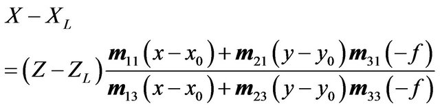
The top-down approach, also known as the ray-tracing approach, employs a collinear equation (Formulas 1 and 2) to cross-reference pixels from the image space with the object space (Figure 3).
 (1)
(1)
 (2)
(2)
where f is focal length of the camera and  are rotation matrix coefficients calculated by the rotation orientations of each axis from image to object space.
  and
and  represent the perspective center of the object and image coordinates. (X, Y, Z) is the image point (x, y) in the object coordinate [10].
2.2. Pixels Allocation Algorithm
For the top-down approach, this study applied the pixel interpolation method to improve the orthoimage quality through pixel allocation by using the Nearest Neighbor (NN) approach. This study also proposed another method for eliminating pixel discontinuity to improve the image quality. This approach is similar to the Bilinear Interpolation (BL) approach for image pixel allocation. The two methods are described below [6]. The flowchart is shown in Figure 4.
2.2.1. Nearest Neighbor (NN) Approach
To increase the computational efficiency of imagery orthorectification using the top-down approach, referenced gray values are typically allocated to the orthoimage directly using the NN method. A schematic diagram of pixel allocation using the NN method is shown in Figure 5. The distances between blank pixels and neighbor pixels should be compared to determine which is the nearest. To carry out this process, as Figure 5 shows, a search mask is applied to each blank pixel to determine its gray value according to the inverse square of the distance for each mask pixel. Furthermore, any blank pixels in the neighboring points must be removed and allocated a gray value.
2.2.2. Bilinear Interpolation (BL) Approach
To resolve blank pixels, this study also applies the BL method for imagery orthorectification to allocate gray values to the pixels, as shown in Figure 6. The position Pa (I, J) is a pixel point in the orthoimage, and I and J are positions in the orthoimage grid system. These results indicate that the four adjacent pixels are highly correlated. Thus, this study applies the BL and area-weighting method to allocate gray values to the adjacent pixels P (i, j), P (i + 1, j), P (i, j + 1), and P (i + 1, j + 1). For a given pixel of an orthoimage, consider the following example using P (i, j). Because P (i, j) is affected by other adjacent points, such as Pa, Pb, Pc, and Pd, repeated filling of the pixel value is required. As shown in Figure 4, this study assigned the gray value of Pa, Pb, Pc, Pd, and other points to P (i, j). Therefore, the gray value of point P (i, j) must be adjusted according to each gray valuefilled pixel and its corresponding weight.
The algorithm proposed in this study is detailed below. In the top-down approach, the pixels of the raw image are cross-referenced to the points Pa in the orthoimage grid system sequentially. For the BL method, the corresponding area of a pixel is used as the weighting factors for the gray value allocation around the neighboring image points of P (i, j), P (i + 1, j), P (i + 1, j + 1), and P (i, j + 1). The weighting factors of Pa are
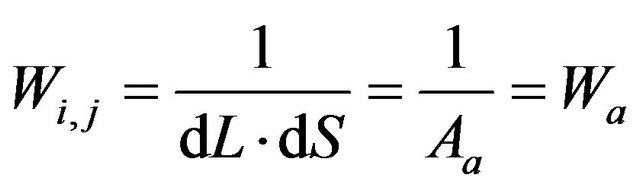 ,
, 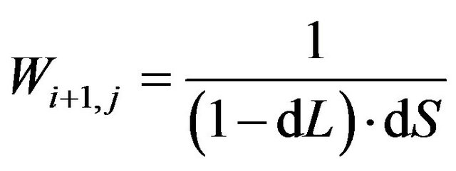 ,
, 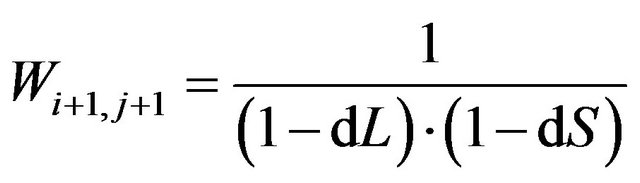 and
and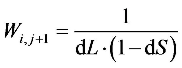 ,
,
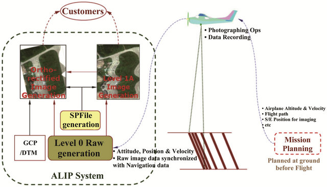
Figure 1. Sketch of the push-broom imaging system.
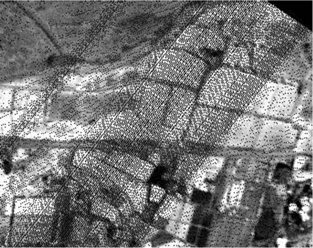
Figure 2. Black lines in orthoimages indicate dramatic altitude variations.
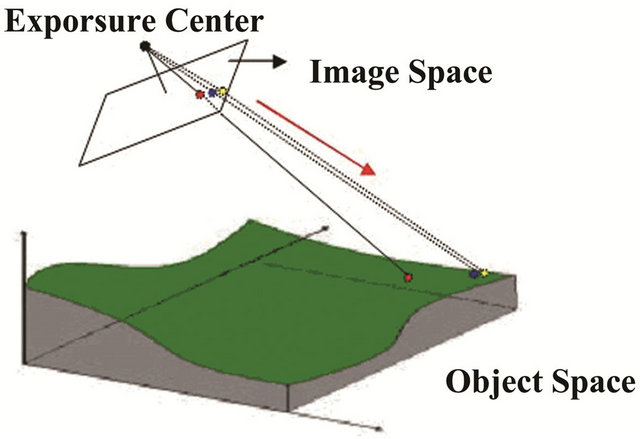
Figure 3. Sketch map of the top-down approach.
where dL = (I – i) and dS = (J – j) are the distance components between Pa(I, J) and P(i, j) in the line and sample directions.
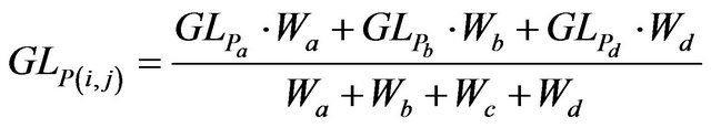
After completing image orthorectification using the previous two steps, a weighted average calculation of the gray values based on the multiple gray values and weighting factors allocated to each image point must be performed. For example, point P (i, j) can be expressed using the following equation:
 (3)
(3)
where GL represents the gray value of the pixel P (i, j),
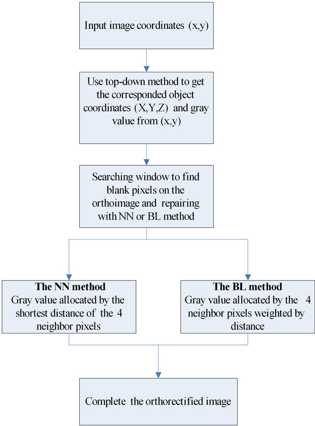
Figure 4. Flowchart of proposed approach.
and W is the weighting factor of the pixel.
To complete the preceding steps, this study applied a dynamic range adjustment to the gray values of the pixels in the orthoimage to ensure their consistency with the range of gray values in the raw image. By applying the presented scheme, pixel discontinuity was eliminated,
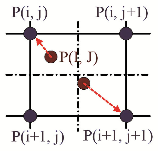
Figure 5. Pixel allocation using the NN method.
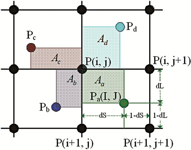
Figure 6. Pixel allocation using the BL method.
and the quality of the orthoimages was substantially improved.
3. Experiments and Discussion
3.1. Experimental Data
We used hyperspectral images retrieved by the HOPE imager [11] to verify the NN and BL methods, and compared the results of these two methods. The HOPE imager is a push-broom imager developed in our colleagues’ previous study. Table 1 shows the specifications of the HOPE imager.
Figure 7 shows a raw image of the near-infrared band (817 nm) of the HOPE hyperspectral imager. The image was captured in the Shengang District of Taichung City, near a major highway interchange. The test field is shown as the red rectangle in Figure 7.
3.2. Experimental Results of the NN Method
When applying the top-down approach, the line and circle of roads are rectified but a number of blank pixels appear in the orthoimages (Figure 8), particularly in the locations affected by dramatic vibrations. As shown in Figure 2, the blank pixels appear as black lines perpendicular to the flight direction. The next step involves filling the blank pixels with the average distance weightings of the search masks using the NN and BL approaches. Through this process, the blank pixels are filled, improving the quality of the orthoimages.
3.3. Experimental Results of NN and BL Approaches
The orthoimage adjusted using the NN and BL appro-
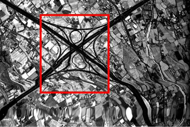
Figure 7. Raw image before orthorectification.
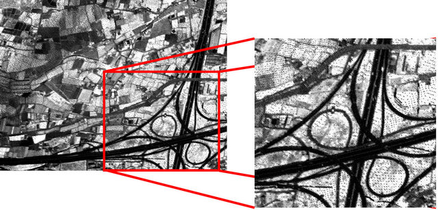
Figure 8. Blank pixels in the orthoimage.
Table 1. Specification of the HOPE imaging system.

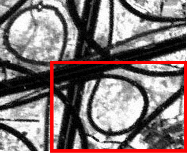
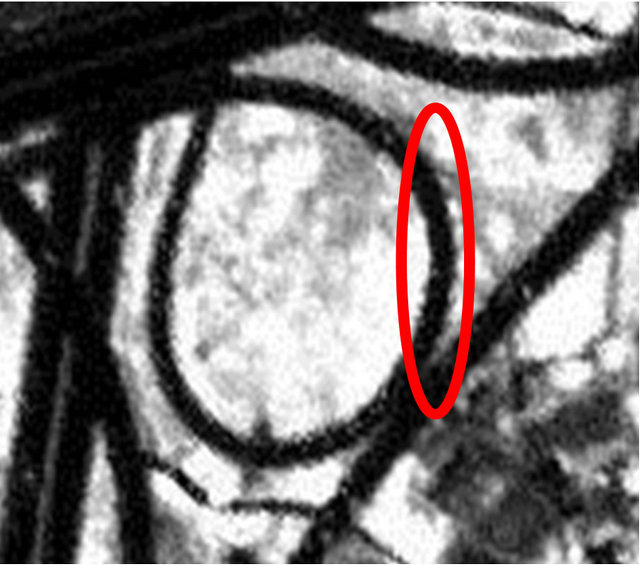
aches contains tiny blank pixels only. The images shown in Figures 9(a) and (b) were produced using the NN and BL methods, respectively, and the red rectangles in these images are magnified in Figures 10(a) and (b). NN and BL use information from cells neighboring a given point in non-weighted (NN) and weighted (BL) schemes for interpolation. NN uses one control pixel closest to the pixel where the interpolated value is required and bilinear interpolation uses the four nearest neighbors. Because the NN method using the gray value of the nearest neighbor pixel is not averaged, some areas of the object have jagged edges. The BL method uses the average of the neighboring pixels weighted by distance, resulting in smooth edges (the red circle shown Figures 10(a) and (b)).
The smoothing effect of BL interpolation on landscapedepiction produces a decrease in the original maxima, while the minima are increased (such as edges of roads and rooftops). The smoothing also produces smeared boundaries (ridges of farms). But NN interpolation produces jagged edges if the wrong values are filled.
Some variation in the gray values of the images pro-
 (a)
(a)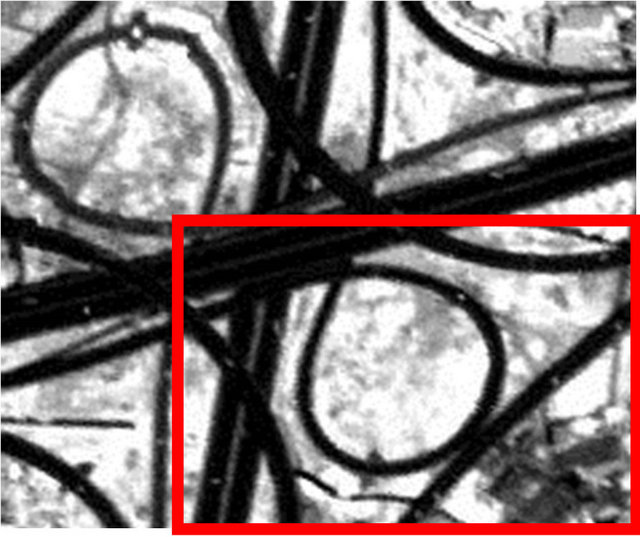 (b)
(b)
Figure 9. (a) Blank pixels filled using NN; (b) Blank pixels filled using BL.
 (a)
(a)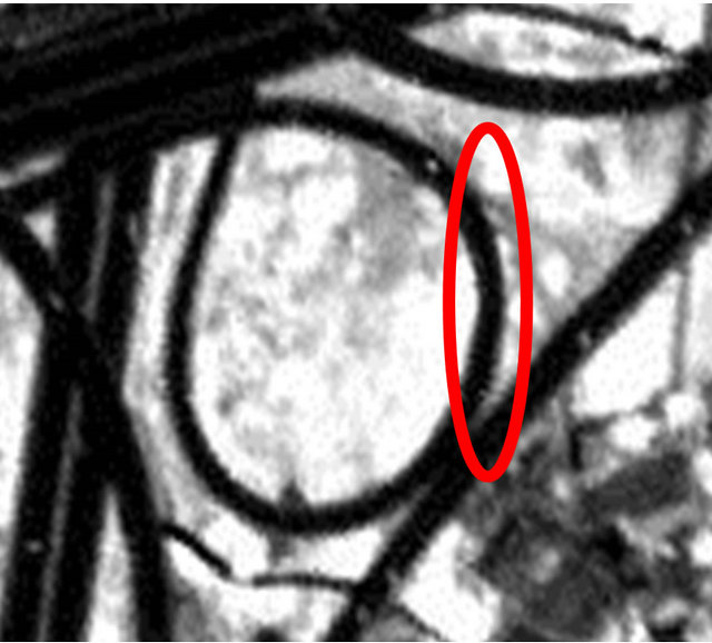 (b)
(b)
Figure 10. (a) Magnification of repaired pixels by NN; (b) Magnification of repaired pixels by BL.
 (a)
(a)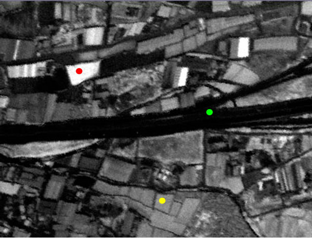 (b)
(b)
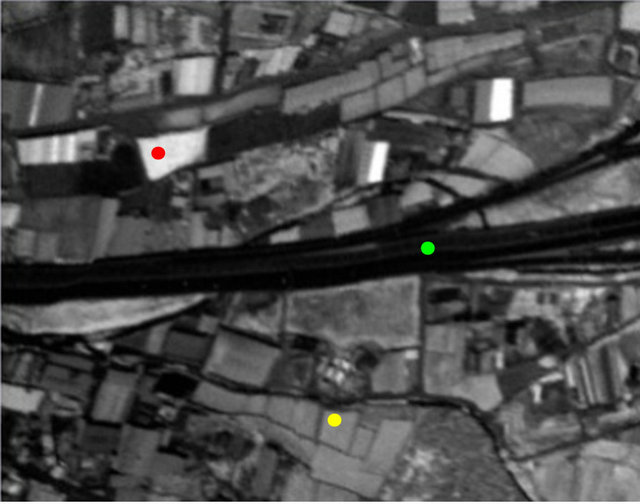
Figure 11. (a) The differing reflection points in the NNrepaired orthoimage; (b) The differing reflection points in the BL-repaired orthoimage.
Table 2. Comparison of the gray values for three points.
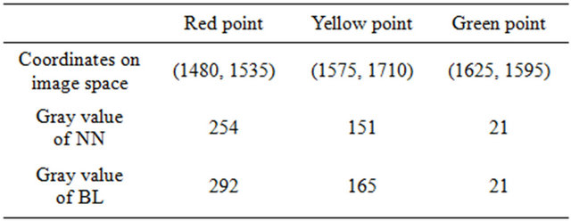
duced using the two methods was anticipated. Thus, this study obtained the differing reflective feature points from the NNand BL-produced orthoimages to compare the gray values. The green, yellow, and red points in Figures 11(a) and (b) represent regions of low, medium, and high reflection, respectively.
The gray values of the three points shown in Table 2 indicate that a higher reflection leads to greater deviation. Furthermore, the gray values of BL-repaired orthoimages are typically higher than those of the NN-repaired orthoimages. This study assumes that the gray values of the BL-repaired orthoimages result from differing ground points that, when accumulated, generate higher values.
4. Conclusion
According to the results obtained using the two proposed algorithms, both methods can substantially improve images which were collected and analyzed by the embedded realtime software. However, the computational efficiency of the NN approach is found to be superior to that of the BL approach due to its simpler computation. However, the details of the image using BL approach are more sophisticated. Thus, the gray values of BL-repaired orthoimages are significantly higher. Further research regarding spectra effects is required to ensure that the radiance of the experimental image is well calibrated. Thus, the higher gray values of BL-repaired orthoimages should be analyzed more extensively in the future. In addition, the establishment of radiometric and geometric calibration dependability is anticipated.
REFERENCES
- W. Mayr and C. Heipke, “A Contribution to Digital Orthophoto Generation,” International Archives of Photogrammetry and Remote Sensing, Vol. 27, No. B11, 1988, pp. 430-439.
- L. C. Chen and L. H. Lee, “Rigorous Generation of Digital Orthophotos from SPOT Images,” Photogrammetric Engineering & Remote Sensing, Vol. 59, No. 5, 1993, pp. 655-661.
- J. Allebach and P. W. Wong, “Edge-Directed Interpolation,” Proceedings of International Conference on Image Processing, Vol. 3, 1996, pp. 707-710.
- C. F. Lee and Y. L. Huang, “An Efficient Image Interpolation Increasing Payload in Reversible Data Hiding,” Expert Systems with Applications, Vol. 39, No. 15, 2012, pp. 6712-6719. doi:10.1016/j.eswa.2011.12.019
- Q. Tang, G. Y. Zhang, G. R. Liu, Z. H. Zhong and Z. C. He, “An Efficient Adaptive Analysis Procedure Using the Edgebased Smoothed Point Interpolation Method (ESPIM) for 2D and 3D Problems,” Engineering Analysis with Boundary Elements, Vol. 36, No. 9, 2012, pp. 1424- 1443. doi:10.1016/j.enganabound.2012.03.007
- R. S. V. Teegavarapu, T. Meskele and C. S. Pathak, “GeoSpatial Grid-Based Transformations of Precipitation Estimates Using Spatial Interpolation Methods,” Computers & Geosciences, Vol. 40, 2012, pp. 28-39. doi:10.1016/j.cageo.2011.07.004
- R. J. Aspinall, W. A. Marcus and J. W. Boardman, “Considerations in Collecting, Processing, and Analyzing High Spatial Resolution Hyperspectral Data for Environmental Investigations,” Geograph System, Vol. 4, No. 1, 2002, pp. 15-29.
- E. Puckrin, C. S. Turcotte, P. Lahaie, D. Dubé, V. Farley, P. Lagueux, F. Marcotte and M. Chamberland, “Airborne Infrared-Hyperspectral Mapping for Detection of Gaseous and Solid Targets,” Chemical, Biological, Radiological, Nuclear, and Explosives (CBRNE) Sensing XI, Vol. 7665, 2010, 10 Pages.
- J. Liu, Y. S. Zhang, D. H. Wang and W. M. Xu, “Geometric Rectification of Airborne Linear Array Pushbroom Imagery Supported by INS/DGPS System,” Journal of Remote Sensing, Vol. 10, No. 1, 2006, pp. 21-26.
- V. A. Grishin, “Accuracy of Measuring Camera Position by Marker Observation,” Journal of Software Engineering and Applications, Vol. 3, No. 10, 2010, pp. 906-913. doi:10.4236/jsea.2010.310107
- M. F. Chen, J. Y. Lai, L. J. Lee and T. M. Huang, “Defective CCDs Detection and Image Restoration Based on Inter-Band Radiance Interpolation for Hyperspectral Imager,” Proceeding of SPIE Asia-Pacific REMOTE Sensing, Vol. 7857, 2010, Article ID: 78570W, 12 Pages.