Journal of Software Engineering and Applications
Vol.5 No.12(2012), Article ID:26220,7 pages DOI:10.4236/jsea.2012.512115
Effort Estimation for Design Activity in Power Plant Equipments
![]()
APEX Institute of Technology & Management Pahala, Bhubaneswar, India.
Email: parimalkugiri@yahoo.co.in
Received September 14th, 2012; revised October 16th, 2012; accepted October 27th, 2012
Keywords: Condenser; Pressure Drop; Heat Load Parameter; COCOMO; Linear Regression Model
ABSTRACT
This Software for Design Activity in power plants Equipments helps the power plant engineers and managers to manage the development and design activities of equipments in the field of power plants. This paper is basically concerned with the computerization of the design activity of Condenser, vital equipment in Heat Exchanger Unit (HEU) of Thermal power plant required for condensing the steam and for further reclaimable purposes to achieve economy. This software will also provide facilities to maintain user profile and the respective work details. The study use a developed model which estimates software effort by studying and analyzing small and medium scale application software.
1. Introduction
Design of power plant equipments, the sizing of equipments are reckoned for the economic and optimum design. So, software has been developed to this effect. This paper will help in finalizing optimum equipments size for tendering and in turn winning orders by the company from the customers. It will provide facilities to maintain equipment profile including all the parameters and the work details required to compute “PRESSURE DROP” parameter for the power equipment like “CONDENSER”. A database is maintained with an aim to keep the records of all those employees who have attempted to access the software. For security purposes a password is also maintained for the software [1].
2. Types of Software
The number of different types of software components for the development of life cycle and associate with the different means of verification and validation with them are mentioned bellow. There are two main different types are new and existing software.
New software: all software written specifically for the application; Existing accessible software: typically software from a similar application that is to be reused and for which all the documentation is available; Existing proprietary software: typically a commercial product or software from another application that meets all or some of the current application requirements but for which little documentation is available; Configurable software: typically software that already exists but is configured for the specific application using data or an application specific input language.
2.1. Equipment Management
The equipments related information, of different phases, would be stored in separate databases [2]. The usage of Notepad files has also been made to store the frequently accessible data. Design engineering or design authority organization, represented by power plant technical services or power plant design engineering. Responsible for:
• Data collection, review, validation and input.
• Component design basis verification.
• Data entry organization.
• Data update procedures.
• Data update request.
• Software Quality Assurance (SQA).
Software Quality Assurance (SQA) also addresses software and hardware testing, and the concept of verification, validation and certification (V, V & C). Software testing and alignment with the appropriate software version and testing phase is tracked as well as interface relationships.
2.2. Software Lifecycle
The Software lifecycle is determined by a combination of technology lifespan and cost factors. Obsolescence for software occurs in different ways, and can be handled by upgrade (enhancement) or eventual replacement with more advanced software. System maintenance by vendor or inhouse technical staff can have a great influence on the useful life of a given solution.
2.3. Software Testing
After development, software is tested in several regimes: Unit testing, system testing, and user testing. If changes were made to existing software in a production environment, regression testing to ensure the changes do not impact other applications will be conducted also.
3. General Perception of the Power Plant
In general power plant consists of some major equipment such as boiler, turbine, condenser and generators. This paper deals with the development process of specific equipment CONDENSER with the help of computer applications. Initially the steam from the boiler equipment is allowed to fall on the blades of the turbine. This turbine consists of a rotor which is then further connected to the rotor of the generator. As soon as steam rotates the blades of the turbine, it further gives motion to the rotor which then further rotates the rotor of the generator. The generator, in addition to the rotor, consists of a rectangular coil which then rotates due to the circular motion of the rotor. The coil rotates in the magnetic field and due to this rotation induces current in it. The current thus generated above is then supplied to the electricity grid which is then distributed to different locations of the city. The basic anatomy of power plants has been elucidated in the Figure 1 given above.
4. Objective of the Software
The Design Activity Software helps design manager to manage resources anywhere (inside or outside the organization) using Internet and gives the liability to enhance the computing using different technologies [2].
• To meet the needs of the Heat Exchanger Unit (HXE).
• To develop a user-friendly interface for the engineers
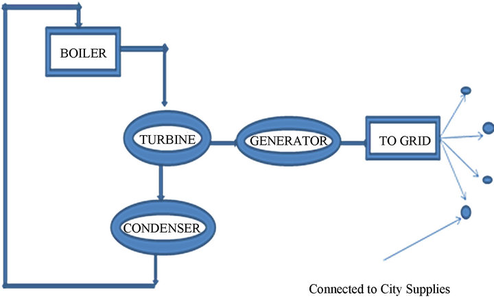
Figure 1. Basic anatomy of a power plant.
at power plants that could provide them an ease to understand and to execute the entire design process of huge plant equipments like Condensers.
• To find ways for human resources to “add value” to a business.
There are numerous pieces of equipment in a power plant, but the maintenance requirements are different for different equipment. Making condition based maintenance in a power plant is a systemic and integrative maintenance management activity which needs a special maintenance decision support system. As a main developing direction of decision support system, intelligent decision support system has got a comprehensive and successful application in many domains.
5. Need for New System
The newly proposed system is based on a user friendly model i.e. the entire interface, the controls and the handling, everything is very easy to learn and master. This model takes it closer to a utility. That means more reach, better performance, predictability, lower cost of ownership and all in all, great peace of mind from all business related problems. The new system has been so designed that it totally works on the user requirement. The objectives that are decided for the proposed system are:
• To computerize the existing system.
• Providing easy and interactive data entry interface.
• Providing effective calculation mechanism.
• Providing a way for analytic report generation.
6. Three Major Modules Involved
6.1. Sizing of Equipments
A program has been prepared to calculate the size of equipment considering the customer requirements. As customer requirements may vary from customer to customer so the first module plays an imperative role in determining the apt parameters required for the design phase of the equipment. Considering all the requirements, the best design is made and then the major parameter “pressure drop” will come into existence.
Since any condenser design is a balance of tube surface, tube length and cooling water quantity, it is the space allowed for the condenser that actually is the deciding factor in the design [1].
6.2. Generation of Performance Curve
Using the concepts of programming we’ll generate the performance curve. This curve basically reflects the accuracy of the equipment. Once we have designed a condenser at the design point (i.e. the design condition) then our next task is to analyze the behavior of condenser under different conditions.
The Heat Exchange Institute (HEI) Standards for steam surface are used to design and predict the performance of the condensers for power plant applications [3,4]. The paper suggests methodology to be followed for examining the performance using the HEI standard values.
6.3. Pressure Drop Computation
In this, basically the difference of pressure between two terminal points of any equipment is reckoned. This is the phase which is actually carried out at different sites that too under different temperature conditions.
7. Comparison between the Existing System and the New System
7.1. Existing System
The existing system is completely manual system which is little bit electronic gadget oriented as it involves the utilization of calculators. This system is very slow and doesn’t handle all the things that are needed to be maintained in the organization. So, the calculations were to be done manually. Basically, the existing one is more error prone as the user is actually open to the commitment of certain human mistakes. The errors could be inefficiency on jotting down the important parameters, wrong calculation or mismanagement in plotting the graph related to the performance of the equipments.
All these shortcomings may lead to certain drastic changes and variations in the actual values of area of different equipments, may affect the analysis phase of equipments where their performance, under different conditions, is judged. As a result all these failures act as an impediment to the “success rate” of the company which is of the prime importance.
Earlier people used to rely on “punching card system” but as punch card workers learned more they were trusted with more complex tasks, and gradually moved toward the design of new procedures and wiring schemes to produce additional reports or tackle new jobs [3]. Figure 2 is Obsolete Punch Card System used in thermal power plants [5].
7.2. New System
On the contrary, the proposed system is made using VB.net as front end which is powerful Graphical User Interface tool. So anyone who doesn’t have a thorough knowledge of computing can use the system. The proposed system manages all aspects of the development process of condensers that is all the information required in the different phase’s right from sizing the equipment till the phase carried out at site after the designing of condenser [4]. It maintains the database of users (who intend to access he system), correction factors and input values.
8. System Analysis Phase
System analysis refers to the process of examining a solution with the intent of improving it through better procedures and methods. System design is the process of planning a new system to either replace or complement an existing system. But before any planning is done, the old system must be thoroughly understood and the requirements determined. System analysis is therefore, the process of gathering and interpreting facts, and using the information to re-connect improvements in the system.
System analysis is conducted with the following objectives in mind:
• Identifying the customer needs.
• Evaluate the system concept for feasibility.
• Perform economic and technical analysis.
• Allocate functions to hardware, software, people, database and other system elements.
• Establish cost and schedule constraints.
• Create a system definition that forms the foundation for all the subsequent engineering work.
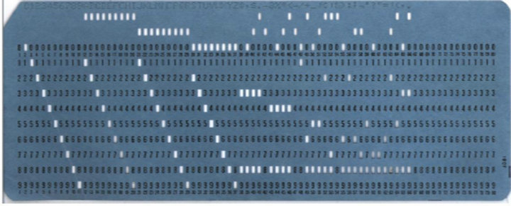
Figure 2. Obsolete punch card system used in thermal power plants.
8.1. Requirement Analysis
At the heart of the system analysis is a detailed understanding of all-important facts of the communication aspects between our company’s internal networks. For this reason, the process of acquiring this information is often termed as detailed investigation. Analyst working closely with our clients, employees and managers has studied the business process. On the basis of the above requirements the capabilities to be achieved from the system are specified which lays a solid foundation for the system design of our module.
8.2. System Design
In the past few years, power plants are constructed with higher parameter, larger size and more automated with power industry developing quickly in China, which makes the system of a power plant become more complex and contain more equipment in quantity and type [6,7]. In order to ensure security and economy of production, power plants need to improve maintenance function in several ways:
• Finding out failure status of maintenance object and maintenance effect.
• Selecting right maintenance policy to achieve expected maintenance effect.
• Establishing quantitative models that quantify index and result in the maintenance policy.
• Monitoring operation status and health status of equipment in the system, to effectively control occurrence and development of failure.
• Making maintenance decision based on current information to effectively prevent occurrence and development of failure, ensure the security of equipment and personnel, and reduce economic lost caused by failure.
• Making maintenance decision and optimization with computer aid for operation and maintenance staff.
9. Equipment Mechanism
Steam available at the turbine, with respect to Figure 1, consists of heat energy [5]. By the time the steam comes out of the turbine at the last stage (after travelling through the turbine) and is ready to enter the Condenser, the steam is at very reduced pressure called as “sub-atmospheric stage” i.e. a stage with pressure less than sub-atmospheric pressure. Since steam is at sub-atmospheric pressure so we need a vessel which is at the sub-atmospheric pressure.
Now, the exhaust of turbine is connected to the equipment or vessel called as “CONDENSER”. It is that power plant equipment in which vacuum is created whose pressure is less than that of the exhaust or residue steam coming from the turbine [8]. This pressure within the vessel is created by other associated equipments called as “Ejectors”. Finally, the condensed steam is fed to the boiler. After this only the latent heat is added to the converted steam.
Refer to Figure 3. Condensate flows in the shell side of the condenser and steam is condensed by the cooling water. Vacuum in the surface condenser i.e. turbine exhaust vacuum is controlled and maintained by vacuum Ejector system of the surface condenser [4]. Figure 4 shows the layout of a typical surface condenser used in steam turbines.
10. Software Design Modules
This paper emphasis on a system that has the following modules designed from the analysis and design of the system:
10.1. Module 1—Sizing of Equipment
The condenser is the key component for the evaporative cooling system of hydro-generators. And the over-all
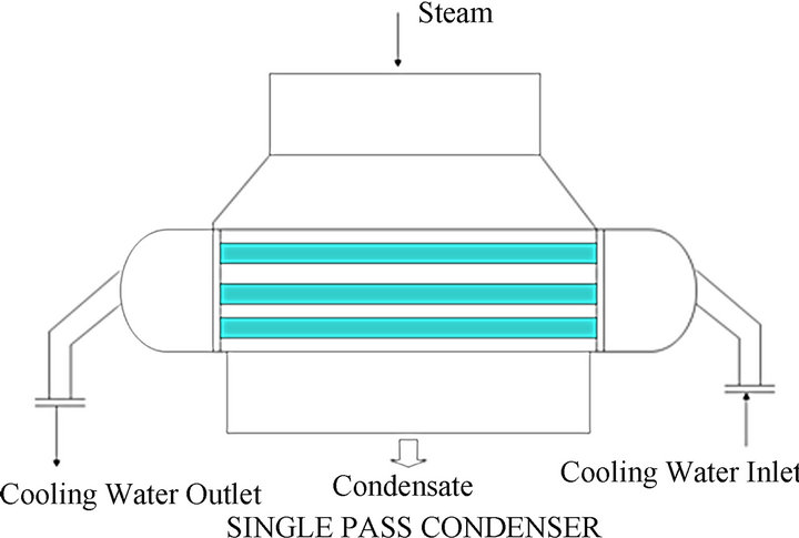
Figure 3. Schematic diagram of single phase condenser.
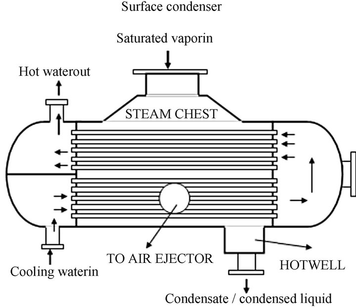
Figure 4. Surface condenser layout.
heat transfer coefficient is primary standard to judge the condenser’s performance [9]. In order to more comprehensively understand the evaporative cooling system and evaluate the condenser’s work efficiency, it is important to calculate the over-all heat transfer coefficient of the condenser. In our works the over-all heat transfer was calculated in each stage and a kind of calculation methods was brought forward, thus the over-all heat transfer which is a value related to a process was proved.
User is provided such an interface in which he is provided with three sub modules [10]:
• Design Information;
• Thermal Calculation; and
• Area of Condenser.
In this way, the application asks the programmer to enter the input information i.e. the parameters as provided by the customer of the Condenser. This information is termed as Design Information. Next, the calculations are carried out on the basis of the formulae as per HEI standards which are already fed in the programs in back end [3]. This phase comprises of Thermal Calculation part. Finally, once the programme is ready with all the input values, he can now find the Area of Condenser as per the given set of values by the customer.
10.2. Module 2—Performance Curves
Once the programmer has analyzed that what should be the area of Condenser for the given set of values now, he can accordingly analyze what exactly will be the performance of this condenser designed under different circumstances. The programmer can determine how condenser would perform at different values of Heat Load (“Q”—the amount of heat a Condenser can condense) and Back Pressure (“Ps”—Condenser Pressure which is less than atmospheric pressure). These two parameters are the most imperative parameters included in the Performance Analysis phase of the Condenser. User is provided with an interface in which he is required to enter the information as per the customer’s SRS and then he is provided with the comparative study of the Condenser at different “Q” and “Ps” with the help of graphical representation as shown in the Figures 5 and 6.
To enhance the performance of the condenser we can also use 3D Modeling capabilities [8] in addition to the technique specified in this section.
Figure 5 shows the performance of condenser at three different temperatures 15 degC, 20 degC and 25 degC.
Figure 6 shows the performance of condenser at four different temperatures 15 degC, 20 degC, 25 degC, 30 degc, 35 degC and 40 degC.
10.3. Module 3—Pressure Drop Computation
This is the last phase of the designing process of the condenser. By this point of time we are ready with our Condenser and now it’s the time for the testing of Condenser at the site where it is to be installed. At this location, we reckon an important factor named “Pressure Drop” which is basically the difference between the pressure at the inlet end and the outlet end of the Condenser [11].
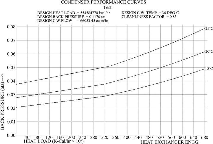
Figure 5. Condenser performance curves.
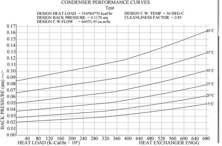
Figure 6. Condenser performance curve.
This parameter is required necessarily because it is the deciding factor for finalizing the size of the pump that is to be attached to the inlet water end. More is the Pressure Drop factor lesser capacity pump will be required and vice versa [12].
11. Software Effort Estimation
One of the major problems faced by project designers in controlling and managing software (SW) project is overrun of effort estimate [13]. The main objective of project designers is making correct decisions and leading to the development in relation to effect estimation. From the developed models, designers addressed that the effort estimate can be made earlier before the SW projects are fully developed, that means, the total Lines of Codes (LOC) of a SW project is counted only when the entire SW is completely developed. COCOMO is one well known method, to estimate the effort of SW projects automatically [14].
11.1. Effort Estimate Model
First, a nominal effort estimate is derived by Boehm using least square technique, which is a basic level of COCOMO. Secondly, the effort estimate is multiplied by a composite multiplier function, m(x), where x is the independent variables. The functional form of the model is defined as
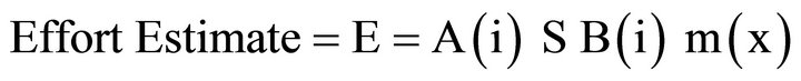
where S is the size of LOC, m(x) is the multiplier function, and the coefficients A(i) and B(i) are derived from a combination of the mode and the level. In this SW A(i) and B(i) are 0.563 and 0.214. With respect to the size of LOC is 1467 and m(x) = 0.0078, then Effort estimate is 0.0209. Which is representing as less fault arises SW development.
11.2. Linear Regression Model (LRM)
Effort estimates are based on information available after detailed design or the program is fully developed [15]. The research model proposed with the following variables. The variable Effort (man-hours) spent by programmer to develop application SW. And other variables are:
Design tools (DEGN_TOOL) = 2;
Programmer Experience (PROG_EXP) = 5;
Team Size (TEM_SIZE) = 2;
Program Complexity (PROG_COM) = 0.8;
Language Experience (LANG_EXP) = 10 yrs.
Regression Model Provides best Effort estimation by using Linear Regression Model. The LRM is hypothesized in the form of equation as
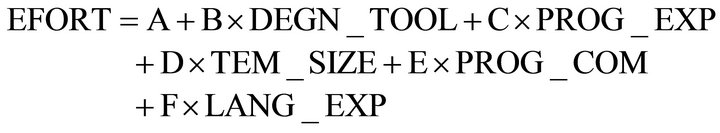
where A, B, C, D, E, and F are to be determined by using normal equations.
Effort = 0.96 represent as high value effort.
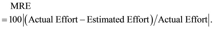
11.3. Quality of Estimation
It indicates more accurate model, Magnitude of Relative Error (MRE) for estimate the quality of accuracy of the effort. The MRE is calculated by using the formula:
12. Conclusion
In this paper we have discussed a computer application that has been designed by keeping in mind the future enhancement of the work of power plants. The most lucrative feature of this application is that the three major modules designed have been given an independent bent of functionality. The advantage of this feature lies in the fact that as an effect of providing independency to each of the module, each on of them can be carried out as a Stand Alone Application. It actually helps different engineers to utilize specific modules according to their need. These further inches up the plausibility of development of separate modules of the project. In this way we have tried to develop a methodology that has completely computerized the designing activity of Condenser which used to be a manual activity amidst the development of power plant equipment—“Condenser”.
REFERENCES
- P. K. Giri and S. Srivastava, “Computer Application for Design Activity in Power Plants,” International Conference on Modeling, Optimization, and Computing (ICMOS 2010), AIP Conference Proceedings, West Bengal, 28-30 October 2010, pp. 250-259. doi:10.1063/1.3516312
- N. Hashemi, “A Relational Database Approach to Power Plant Design and Operating Plant Services,” IEEE Transactions on Energy Conversion, Vol. 3, No. 3, 1988, pp. 487-490.
- M. Botting and D. Kelly, “Computer Program Documentation System Condenser Design,” David Taylor Model Basin Reports, DOME, 1966. http://oai.dtic.mil/oai/oai?verb=getRecord&metadataPrefix=html&identifier=AD0650571
- K. S. S. Raj, “Deviations in Predicted Condenser Performance for Power Plants Using HEI Correction Factors: A Case Study,” ASME Power Conference (POWER2006), Atlanta, 2-4 May 2006.
- G. G. Rajan, “Energy Saving in Steam Systems”. www.Klmtechgroup.Com.
- J. Lang, “Design Procedure for Heat Exchangers on Aspen-Plus Software,” Design Manual, 1999. http://cbe.sdsmt.edu/nsfproj/aspen/condenser.pdf
- J. Lang, “Condenser Design on Aspen-Plus Software,” ©SDSM&T, Rapid City, 2000.
- Aspen Plus Simulator 10.0-1. User Interface, 1998.
- http://pdf.ebooks6.com/Design-Procedure-for-a-Heat-Exchanger-on-the-AspenPlus-Software-pdf-e15431.pdf
- X.-F. Dong, “Study on Intelligent Maintenance Decision Support System Using for Power Plant Equipment,” 2008 Automation and Logistics, 2008. ICAL 2008. IEEE International Conference, Qingdao, 1-3 September 2008, pp. 96-100.
- K. Darius, “Application of Intelligent Computer Aided Design Techniiques to Power Plant Design and Operation,” Power Engineering Review, IEEE, PER-7, December 1987, pp. 34-35
- S. I. K. Wu, “The Quality of Design Team Actors on Software Effort Estimation,” Service Operations and Logistics, and Informatics (SOLI), IEEE International Conference, 21-23 June 2006.
- S. Wu and I. Kuan, “A Component-Based Approach to Effort Estimation,” The 4th International Conference on Wireless Communications, Networking and Mobile Computing (WiCOM 2008), Dalian, 12-14 October 2008, pp. 28-36.
- J. C. Munson and T. M. Khoshgoftaar, “Regression Modeling of Software Quality: Empirical Investigation,” Information and Software Technology, Vol. 32, No. 2, 1990, pp. 106-114. doi:10.1016/0950-5849(90)90109-5
- P. K. Suri and P. Ranjan, “Comparative Analysis of Software Effort Estimation Techniques,” International Journal of Computer Applications, Vol. 48, No. 21, 2012, pp. 12-19.