Engineering
Vol.11 No.05(2019), Article ID:92784,7 pages
10.4236/eng.2019.115021
Determination of the Law of Motion of the Yarn in the Spin Intensifier
Sherzod Ahmadjanovich Korabayev1, Mardonov Botir Mardonovich2, Matismailov Saypila Lolashbayevich3, Melibоyev Umarjоn Xaydarоvich4
1Department of Technology of Products of Textile Industry, Namangan Institute of Engineering and Technology, Namangan, Uzbekistan
2Faculty of Technology of Cotton Industry, Tashkent Institute of Textile and Light Industry, Tashkent, Uzbekistan
3Department of Spinning Technology, Tashkent Institute of Textile and Light Industry, Tashkent, Uzbekistan
4Faculty of Engineering and Technology, Namangan Institute of Engineering and Technology, Namangan, Uzbekistan

Copyright © 2019 by author(s) and Scientific Research Publishing Inc.
This work is licensed under the Creative Commons Attribution International License (CC BY 4.0).
http://creativecommons.org/licenses/by/4.0/


Received: April 2, 2019; Accepted: May 27, 2019; Published: May 30, 2019
ABSTRACT
The article is devoted to the study of spreading of the twisted yarn in a spinning cell. The article presents the scheme and principle of operation of the effective design of the yarn-output tube of pneumomechanical spinning machine. To determine the law of motion of a roller installed in a yarn-output tube, the tension of the thread enveloping the surface of the rotating roller was studied, as a result of which the equation of its motion was obtained. As a result of solving the equation, the values of the thread tension on the surface of the rotating roller are obtained. The dependences of the change in the tension of the thread in time are obtained depending on the angle of rotation and the mass of the roller. The recommended design of the yarn-output tube allows increasing the strength characteristics of the pneumomechanical yarn.
Keywords:
Yarn, Twist, Pneumatic Spinning Machine, Tube, Inclined Flute, Roller

1. Introduction
One of the important mechanical properties of the yarn is the breaking load, which determines the stability of the spinning process [1] .
Cell pneumomechanical spinning method is most prevalent for the production of high and medium linear yarn from cotton, chemical fibers and their mixtures [2] .
The essence of this method is to transform the tape into a discrete stream of fibers, to form a wedge-shaped fibrous ribbon in the form of an open ring in the spinneret groove of the stream and to form a yarn by twisting it out of the cell using exhaust rollers.
Modernization of pneumatic spinning machines continues to improve the efficiency of pneumatic spinning, improve the quality of yarn and reduce breakage, rational use of energy in the formation of yarn, as described in [3] .
The thread tension and twist distribution under conditions of constant rotation of the cell are numerically simulated, where the influence of various dimensionless spinning parameters on the thread tension and twist distribution is evaluated [4] . Further, in the movement of the yarn and the dynamics of the yarn during camera rotation are considered, which provides an analytical model for determining the level of twist at the yarn pickup point when the spinning cell is rotated [5] . The resulting model is able to quantitatively distribute the twist in the contact area of friction inside the spinning cell in terms of tension and operating parameters of the machine [6] . Torsion funnel with a special friction surface acts as a torsional twisting body. To ensure a stable process with minimal breakage, it is necessary that the torque generated by the thread funnel is maximum. The effect of false torsion was obtained by a number of scientists [7] .
Based on this, the authors of this article studied the movement of yarn in the zone of the spin intensifier of a spinning machine.
In order to reduce the axial force of the yarn at each site of its allotment, the modernization of the corresponding devices continues. Some of them are discussed below.
In the implementation of these processes are used air and mechanical effects. The phenomena occurring during these processes and their patterns were disclosed in the works of A.G. Sevostyanova, I. Ripki, J. Lunenschles et al. [2] .
Recommended yarn-output tube for yarn spinning device, which contains the first and second sections, rigidly interconnected by means of a connecting corner and equipped with a ceramic insert with inclined grooves on the working surface, the first section of tube is connected to the spinning cell [8] . The disadvantage of this design of the tube for stretching the yarn in the spinning device is excessive braking of the yarn when it comes into contact with the inclined corrugated surface of the ceramic insert, as well as one-sided mixing of the yarn in the transverse direction due to fixed inclined corrugated working surface of the insert, which leads to additional elongation of the yarn and reduce its torsion.
In order to increase the strength characteristics of the yarn, the design of the yarn-output tube for spinning device has been improved (Figure 1), which allows reducing the friction resistance and ensuring the mobility of the corrugated surface of the insert with the necessary centering of the yarn being pulled.
In the process of spinning unit operation, the yarn 3 (Figure 1) is pulled out through the tubular Sections 1 and 2. In the transition zone of the tubular Sections 1 and 2, the yarn 3 contacts the inclined grooves 8 of the ceramic roller 5, which rotates around the axis 7. Due to the rotation of the ceramic roller 6, the

Figure 1. Yarn-output tube of spinning device.
resistance from it to the stretched yarn 3 will be smaller, which virtually eliminates additional elongation of the yarn deformation 3. In addition, due to the inclined flute 8 when the roller 6 is rotated, effective torsion of the yarn 3 occurs [9] .
The recommended design of the tube for output the yarn allows an increase in the strength characteristics of the resulting yarn [10] .
To achieve this goal, i.e., to improve the distribution of the torsion in the yarn output through the tube, an analysis was made of the work of the roller, taking into account the tension of the yarn being removed.
2. Formulation of the Problem
The problem of contour-based motion of a thread along the surface of a funnel, which seems to be an arc of a circle, is considered. In this case, the arc moves around a fixed axis with a velocity of ve(t) and each point of the thread has a speed vr relatively to the arc, following [11] , the contour-based motion of the thread is studied by the Euler method. The motion of the filament in Euler coordinates is described by partial differential equations with two arguments s, t (s is the arc length, t is time), and its contour-based motion is described by an ordinary differential equation with one argument s. In the case of contour movement of an inextensible thread, when its shape does not change, all its points at a given
moment of time have the same modulus speed, then it should be
assumed that The relative thread speed is a function for only time t. We enter the natural unit coordinates and , directed respectively along the tangent and the contour normal, and write the relative speed of the thread in the form: . The total acceleration of an arbitrary point of the thread is represented as the sum of the relative and portable accelerations.
At the same time, the projections of relative and portable accelerations on the connected axes look like [11] .
, , ,
Here R is the radius of the arc of a circle.
We neglect the weight of the thread, taking into account along the arc of coverage only the friction force τ and the normal reaction q. Considering that for these forces the Amonton-Coulomb law is satisfied, the basic equation of the contour movement along the arc of a circle of a thread is represented as [11] [12] [13]
(1)
where T = T(s, t) is the tension, µ—is the linear mass of the thread. Assuming that the thread moves in the direction of rotation of the circular arc (funnels), we obtain
at , at , at (2)
Taking , Equation (1) in view of (2) we bring to the form
, at (3)
where k-is the coefficient of friction between the thread and the surface of the funnel, φ = α—is the arc of coverage, N = Rq is the normal force. The value of the angle φ = 0 corresponds to the point of crowding of the filament to the funnel, φ = α the vanishing point of the filament from the contour. Integrating the first equation from (2) under the condition T(α) = T0, we obtain
(4)
(5)
3. Solution Method
The tension of the thread T and the normal force N by Formulas (4) and (5) will be determined as soon as the speeds vr and vв are known. They are determined from additional physical conditions. Consider the mode of motion of the thread with a constant relative speed i.e. set vr = v0 = const In Formulas (4) and (5), we should set vr = v0 and vr = 0. In this case, the contour (roller) must satisfy the equation of rotation
where J = MR2 is the moment of inertia of the roller. The last equation is written as
(6)
where , M-roller weight
Thus, under the action of the apparent tension of the thread , the roller makes an equally accelerated motion with acceleration . This
movement continues until the time t = t0, at which the speed of the roller will be equal to the relative speed, i.e. vв = v0 from this condition we find .
4. Analysis of Results
Figure 2 shows the dependence of the speed of rotation of the roller on time for various values of the tension T0 and the mass of the roller M.
It is assumed in the calculations: k = 0.3. R = 0.005 m. vh = 100 m/min. Figure 3 and Figure 4 show the graphs of the distribution of the tension of the thread along the contact arc for different values of the tension T (cH), the wrap angles α and the mass of the roller.
From the graphs presented in Figure 2, it follows that the linear speed of the roller in a short time (t0 ≈ 10-6-10-5 min) reaches the thread speed.
An analysis of the tension distribution curves along the contact arc shown in Figure 3 and Figure 4 show that the presence of a roller, depending on its mass, significantly reduces the tension along the arc of contact.

Figure 2. Dependence of the roller linear speed vв (m/min) on the time t(min) for different values of the tension T0 (cH) and the mass of the roller M(gram): 1—mass of the roller M = 3 gram; 2—mass of the roller M = 4 gram; 3—mass of the roller M = 6 gram; 4—mass of the roller M = 8 gram. The roller which is given in Figure 1 (7).

Figure 3. The dependence of the tension on the angle φ (rad) for with different values of the angle and mass of the roller: 1—mass of the roller M = 3 gram, 2—mass of the roller M = 4 gram, 3—mass of the roller M = 6 gram, 4—mass of the roller M = 10 gram, 5—fixed roller.
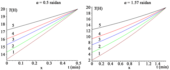
Figure 4. The dependence of the tension T (H) from angle at different values of the angle and mass of the roller M(gram): 1—mass of the roller M = 3 gram, 2—mass of the roller M = 4 gram, 3—mass of the roller M = 6 gram, 4—mass of the roller M = 10 gram, 5—fixed roller.
5. Conclusions
In the study of the spinning in the spinner as described above, the rod of the rolling rolled rope will have a yarn velocity at the moment of theoretical study of the law of the rolled rod in the effective construction of the yarn tractor pneumatic spinning machine. As a result, the rotating roller decreases the tension in the contact area by moving the yarn to ensure a uniform baking across the entire feeding zone and to increase the yarn’s stiffness.
1) The recommended design of the tube for output the yarn of spinning machine, allows an increase in the strength characteristics of the produced yarn.
2) It is established that the roller after contact with a moving thread almost instantly gains the speed of the thread.
3) As a result of the joint movement of the thread with the roller, the tension of the thread at the point of its crowding to the surface decreases with decreasing mass of the roller.
4) Reducing the tension in the zone of contact of the thread with a moving thread allows for a uniform twist along the entire length of the torsion zone.
Conflicts of Interest
The authors declare no conflicts of interest regarding the publication of this paper.
Cite this paper
Korabayev, S.A., Mardonovich, M.B., Lolashbayevich, M.S. and Xaydarоvich, M.U. (2019) Determination of the Law of Motion of the Yarn in the Spin Intensifier. Engineering, 11, 300-306. https://doi.org/10.4236/eng.2019.115021
References
- 1. Astashev, M.M. (2003) Thesis for the Degree of Candidate of Technical Sciences. Improvement of Technological Operations of Feeding the Formation of Yarn on Rotor Spinning Machines. Ivanova.
- 2. Sevostyanov, A.G. (1989) Mechanical Technology of Textile Materials. Moscow Legprombytizdat.
- 3. Migushov, I.I. (1984) Mechanics of Textile Yarn and Fabric: Monogr. In: Mirushov, I.I., Solovyov, A.N. and Kiryukhin, S.M., Eds. Light and Food Industry, Moscow, 130s.
- 4. Xu, B.G. and Tao, X.M. (2003) Integrated Approach to Dynamic Analysis of Yarn Twist Distribution in Rotor Spinning Part I: Steady State. Textile Research Journal, 79-89. https://doi.org/10.1177/004051750307300116
- 5. Ba, T. and Huang, X.B. (2003) Modeling the Twist Level at the Peeling Point in Rotor Spinning. TRJ, 390-395. https://doi.org/10.1177/004051750307300504
- 6. Guo, B.P., Tao, X.M. and Lo, T. (2000) A Mechanical Model of Yarn Twist Blockage in Rotor Spinning. TRJ, 11-17 https://doi.org/10.1177/004051750007000103
- 7. Kiselev, R.V. (2013) Determination of the Torque Generated by the Thread Funnel When Forming the Reinforced Thread of the Pneumatic Mechanical Spinning Method. Bulletin, 1, 22-28. https://readera.ru/142184805
- 8. Patent US 5044151, 09/03/1991 D01H 4/40.
- 9. Korabayev, Sh.A., Djurayev, A.D. and Matismailov, S.L. (2018) Efficient Tubing Design for Spinning Yarn in a Spinning Device. TITLP, 4-5.
- 10. Korabayev, Sh.A., Djurayev, A.D. and Matismailov, S.L. (2018) Perfection of Designs and Theoretical Bases of Calculatingroller Tubes for Yarning. International Journal of Advanced Research in Science, Engineering and Technology, IJARSET, 5, 75-83.
- 11. Scherbakov, V.P. (2013) Applied and Structural Mechanics of Fibrous Materials. M. OOO, “Tiso Print”, 304.
- 12. Abdukarimovich, M.O., Ibragimovich, A.K. and Sharipjanovich, S.O. (2018) Designing a New Design of a Loading Cylinder for Pneumomechanical Spinning Machines. Engineering, 10, 345-356. https://doi.org/10.4236/eng.2018.106025
- 13. Abbazov, I., Sarimsakov, O., Khodjiev, M. and Mardonov, B. (2018) Waste Produced at Cotton Waste Factories. American Journal ASCIT Communications, 5, 22-28.