Engineering
Vol.06 No.08(2014), Article ID:47761,8 pages
10.4236/eng.2014.68044
Mechanistic Model versus Artificial Neural Network Model of a Single-Cell PEMFC
Brigitte Grondin-Perez, Sébastien Roche, Carole Lebreton, Michel Benne, Cédric Damour, Jean-Jacques Amangoua Kadjo
University of La Reunion, Saint-Denis, France
Email: bgrondin@univ-reunion.fr
Copyright © 2014 by authors and Scientific Research Publishing Inc.
This work is licensed under the Creative Commons Attribution International License (CC BY).
http://creativecommons.org/licenses/by/4.0/


Received 23 April 2014; revised 26 May 2014; accepted 10 June 2014
ABSTRACT
Model-based controllers can significantly improve the performance of Proton Exchange Membrane Fuel Cell (PEMFC) systems. However, the complexity of these strategies constraints large scale implementation. In this work, with a view to reduce complexity without affecting performance, two different modeling approaches of a single-cell PEMFC are investigated. A mechanistic model, describing all internal phenomena in a single-cell, and an artificial neural network (ANN) model are tested. To perform this work, databases are measured on a pilot plant. The identification of the two models involves the optimization of the operating conditions in order to build rich databases. The two different models benefits and drawbacks are pointed out using statistical error criteria. Regarding model-based control approach, the computational time of these models is compared during the validation step.
Keywords:
Mechanistic Model, Artificial Neural Network Model, Proton Exchange Membrane Fuel Cell, Real-Time Experiment

1. Introduction
Climate warning issues and fossil fuels depletion stimulate the development of new technologies for energy conversion. Apart from infrastructure related to production, storage and transport, hydrogen appears to be a suitable alternative to fossil fuels.
Because it’s a common naturally occurring element, hydrogen represents a promising energy vector. In this context, fuel cells (FC) hold great promise for low emission power generation, especially PEM (proton exchange membrane) fuel cells (PEMFC) because of their high power density and low operating temperature. Nevertheless, their performance remains limited by factors related to gas supply and membrane water content. These converters allow turning hydrogen chemical energy into electricity with low environmental impacts. However, their cost has to be reduced, in order to make hydrogen a possible substitute to common power sources. Nowadays, lots of researches deal with PEMFC modeling and control challenges to make it competitive and improve its performance.
Many fuel cell models have already been developed for twenty years. They can be sorted by three categories: mechanistic, semi-empirical and empirical models.
Mechanistic models describe physical, chemical and electrical phenomena using algebraic laws. This kind of models is used to achieve system supervision, diagnosis [1] , or control strategies [2] -[4] . Nevertheless, PEMFC systems are characterized by a very short time response (less than 1 s). The complexity of mechanistic approach can limit online model-based control.
For many years, ANNs are commonly used to model complex systems. They can approximate nonlinear functions between inputs and outputs from incomplete databases and with specific accuracy. For the past decade, many authors have concentrated their research on ANNs with different levels of complexity to model fuel cell systems [5] -[7] .
This work deals with the comparison between mechanistic and ANN models of a single-cell PEMFC pilot. We focus on the identification of the simplest ANN structure in order to develop easily to implement model- based control schemes. In a first part, FC system and test bench are described. The second and third parts give the different laws forming the mechanistic model and the methodology used to identify the most suitable ANN model able to ensure satisfactory accuracy. Then, the analysis of the results is carried out and perspectives are developed.
2. PEMFC Process System
2.1. FC System
PEMFC system consists of a polymer electrolyte membrane sandwiched between two electrodes: an anode and a cathode. Hydrogen fuel passes through the Gas Diffusion Layer (GDL), and is processed at the anode where electrons are separated from protons on the surface of a catalyst. Protons pass through the membrane to the cathode side of the cell while electrons travel in an external circuit, generating an electrical current. On the cathode side, protons and electrons with oxygen are combined to produce water, which is expelled as the only waste product. Oxygen can be provided in a purified form, or extracted at the electrode directly from the ambient air. Figure 1 describes the main phenomena in PEMFC.
2.2. Pilote Plant
The home fuel cell assembling consists of a single-cell, with a 50 cm2 active area. The membrane is made of Nafion 115, and the MEA (membrane electrodes assembling) is produced by Paxitech. Bipolar plates are clamped at 12 N.m, after torque optimization. The used test station depicted by Figure 2 is manufactured by Fuel Cell Technologies. It allows configuring and monitoring a wide range of parameters, described as below:

Figure 1. Fuel cell description.

Figure 2. Simplified diagram of fuel cell system.
・ Fuel cell temperature, measured at cathode side.
・ Humidification temperatures, anodic and cathodic.
・ Inlet gas temperatures, anodic and cathodic.
・ Inlet gas mass flows, anodic and cathodic.
・ Outlet back-pressures, anodic and cathodic.
All parameters are controlled by a graphic Labview interface developed by Fuel Cell Technologies. An electronic load allows current or voltage control. This test station enables to build databases, and to implement control strategies.
3. Mechanistic Model
The PEMFC system is a nonlinear, multivariable electrochemical system that is hard to model. Describing this system requires the understanding of complex internal phenomena at molecular level. A large number of publications [8] [9] targets the modelling of fuel cell behavior describing internal phenomena. These mechanistic approaches are usually focused on the electrochemistry, thermodynamics and fluid mechanics. They describe mathematically the entire physical environment of electrochemical reaction.
The developed model is a one-dimensional and dynamical PEMFC model, extracted from [4] . This model involves two main parts: a dynamical fluidic model and an electrochemical static model, developed in the next parts. The model assumptions are summarized:
・ Nafion 115 is used.
・ Gases are considered as ideal.
・ Anode is fed by hydrogen, cathode by compressed air (21% oxygen and 79% nitrogen).
・ Gas are 100% humidified.
・ Temperature is homogenous through the stack.
・ Outlet pressure and inside fuel cell pressure are equal.
・ Thanks to electrochemical reactions high rapidity compared to mass transfer reactions, electrochemical model is assumed to be static.
3.1. Electrochemical Static Model
This model part enables output cell voltage prediction. Voltage equations are based on Nernst and Tafel equations, written as below:
 (1)
(1)
where  is the Nernst potential, actually the thermodynamic potential, defined by the Nernst equation [10] :
 (2)
(2)
with:
・ ![]() , is the change in molar Gibbs free energy of formation R, is universal gas constant, T is the fuel cell temperature, F the Faraday constant.
, is the change in molar Gibbs free energy of formation R, is universal gas constant, T is the fuel cell temperature, F the Faraday constant.
・ ![]() , is hydrogen partial pressure at anode side, and
, is hydrogen partial pressure at anode side, and ![]() the oxygen partial pressure at cathode side.
the oxygen partial pressure at cathode side.
・ ![]() ,
, ![]() and
and ![]() are activation, ohmic and concentration losses, named over-voltages.
are activation, ohmic and concentration losses, named over-voltages.
Activation over-voltageis defined by [11] as:
![]() (3)
(3)
![]() (4)
(4)
![]() ,
, ![]() and
and  are constant parametric coefficients, empirically determined, as well as
  parameters.
  and
and  are oxygen and hydrogen concentrations, and
  the active fuel cell area.
Ohmic losses are given by:
 (5)
(5)
where  is the membrane resistance, and
  is the resistance of other components (bipolar plates and wires).
  value depends on the membrane water content
  [12] :
 (6)
(6)
 (7)
(7)
where  is the membrane thickness, and
  the average water activity between
  and
and , the anode and cathode water activities:
 (8)
(8)
with  is water vapor partial pressures, and
  is vapor saturation pressure.
 and
and  empirical parameters are difficult to estimate. Generally a trial and error method is used.
3.2. Fluidic Model
3.2.1. Anode Fluidic Model
At anode side, a part of hydrogen reacts. Hydrogen pressure must be determined in order to estimate cell voltage.
Mass balance equations have to be solved numerically:
 (9)
(9)
where  are inlet or outlet mass flow rates, or the mass flow of hydrogen which reacts at electrode surface.
  is hydrogen gas constant and
  is anodic volume.
The water partial pressure depends on ,
,  the outlet vapor and liquid water mass flow rates:
 (10)
(10)
 is inlet vapor mass flow rate, and
  the vapor mass flow rate passing through the membrane.
3.2.2. Cathode Fluidic Model
Humidified air reacts with electrons and protons at cathode side. This reaction produces water and heat. As anode partial pressures, differential equations have to be solved:
 (11)
(11)
 (12)
(12)
 (13)
(13)
where  are gas constants,
  the cathodic volume and
  the vapor water generated at cathode side.
3.2.3. Membrane Hydration Model
Electro-osmotic and back-diffusion water flows induce water circulation. Water flow has important impacts in membrane water content, and thus in ohmic losses. Water mass flow rate across the membrane has to be defined:
 (14)
(14)
where  is the water flow through the membrane, expressed by:
 (15)
(15)
where  is the electro-osmotic drag coefficient,
  the water concentration at anode/cathode surface and
  the diffusion coefficient.
Describing all internal phenomena of this system leads to complex nonlinear laws with unknown parameters. Generally a trial and error method is used to match the model.
4. Neural Network Model of a PEMFC
The development of the mechanistic model highlights two main difficulties:
・ Equations describing the process include numerous empirical parameters. Their estimation leads to develop a model characteristic of a particular cell in a particular operating area.
・ Estimation of these parameters needs to implement algorithms of optimization which lead to complex computing [13] .
Both limit the efficiency of the process control.
Because they can approximate nonlinear functions with incomplete data and a specific accuracy, ANNs appear to be suitable to model complex systems such as PEMFC.
The identification of ANNs models follows the general methodology in four steps.
4.1. Data Processing
To build relevant databases for model identification, different operating conditions should be tested. Fuel cell experimental data can take a large amount of operation conditions. Temperatures, pressures, hydrogen and oxygen flows, have an impact on FC performance. In order to optimize the richness of databases, nominal standard conditions are used in experimental tests for FC supervision: anodic and cathodic inlet pressures are set out to 300 kPa and different amplitudes of step current signals are injected on FC. With the objective of measuring the system response over a wide range of values, a suitable design of experiments is used to consider two other variables simultaneously:
・ FC temperature range is 60˚C to 80˚C: .
.
・ RH range is 60% to 100%. (RH is influenced by humidifier temperature and preheater temperature.
Relative humidity (RH) can be determined by the following equation [14] :
 (16)
(16)
 (17)
(17)
The coefficients used in the Equation (17) are defined in Table 1.
A three levels design of experiments is set (levels −1, 0 and +1). Controlled factors levels are based on high and low manufacturer advisable bounds. The level 0 is centered on −1 and +1 levels (Table 2). With 3 levels and 2 controlled factors, the entire design of experiments includes 9 experiments. The design of experiments is described on Table 3.
4.2. ANN Model Structure
The identified model consists of a 3 layers network. The activation function in hidden layer is a nonlinear hyperbolic tangent function [15] and the number of hidden neurons is set by trial and error method. The output layer has a linear activation function. The structure is a nonlinear autoregressive with exogenous input (NNARX) model:
 (18)
(18)

Table 1. Pressure saturation coefficients.
Table 2. Factors levels.
Table 3. Design of experiments.
A large number of variables are collected by the acquisition system during experimental recorded tests. Ranking these variables using correlation feature can strongly reduce the number of mandatory inputs. All variables gathered by the instrumentations are computed by probe feature method (PFM), a methodology based on Gram-Schmidt orthogonalization and described by Stoppiglia [16] . Not relevant variables are removed from the input list. Dominant variables, selected and ranked in the top of the pertinent list, are set for ANN learning.
Model inputs are appointed as follow: temperature, cathode humidity temperature and current. The output is the output voltage.
4.3. Parameters Estimation
The model parameters to estimate are the network weights. They are calculated according to a cost function, based on classical quadratic convergence criterion:
 (19)
(19)
where  is the matrix of network parameters,
  is the cost function parameterized by
 ,
,  and
and  are respectively input and output system at instant t and
  is the estimated output. The robust Levenberg-Marquardt algorithm is used as optimization method. The stop criteria are based on a number of iterations and the mean squared error (MSE).
4.4. Model Validation
Validation is carried out on 20% saved database. To check the ANN performance, the sum of squared error (SSE) is used and denotes the overall error between estimated and experimental outputs. The root mean squared error (RSME) criterion is computed to perform the ANN accuracy.
5. Results
5.1. Mechanistic and ANN Models Accuracy
This section is dedicated to the FC mechanistic and ANN models performance. These models are expected to predict the output voltage of the single-cell PEMFC one step ahead once the operating conditions are set out.In this aim, various network architectures have been investigated to determine which one will provide the best prediction in terms of computational speed and accuracy. The best-chosen structure is about 3 inputs, 3 hidden neurons and one linear output neuron. The following picture shows the mechanistic model output versus ANN model output.
Figure 3 allows comparing the models accuracy. The dynamic of the process is well matched by the two models that can reproduce the short time response of this system. Nevertheless, it can be observed that mechanistic model presents some steady state offset. This offset may be important depending of the operating area. This is not surprise considering the four empirical parameters of static part of the mechanistic model.
These results mean that the four parameters haven’t been optimally estimated. Two other reasons can explain this offset. The first one is the validity of the model assumptions, and the second one results from the initialization of the state variables.
It is important to note that the ANN model is able to match the process behavior all over operating area. To quantify the models accuracy three criteria have been calculated: Sum Square Error (SSE), Mean Square Error (MSE) and Root Mean Square Error(RMSE).The good performance of the ANN model is confirmed by these error criteria shown in Table 4.
5.2. Computational Time
Regarding fast dynamic system, the computational time becomes a relevant factor to achieve online control. This characteristic is important since the model should be embedded in closed loop control. Figure 4 depicts the computational time during the validation step. The computational time between two samples is the same for the validated ANN model. Nevertheless, this time fluctuates for the mechanistic model depending on signal variation.

Figure 3. Predicted output voltage.
Table 4. Error criteria.
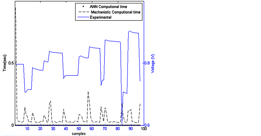
Figure 4. Computational time for both models.
6. Conclusion and Perspectives
In this work, two different modeling approaches have been investigated to model a PEMFC system. In the one hand, a mechanistic model has been identified. This first approach has required, among other things, the estimation of several parameters. In the other hand, an ANN model has been designed. This model is expected to predict the output voltage of the PEMFC once temperature, cathode humidity temperature and load current are available. Performance of both models, in terms of accuracy and computational time efficiency, has been investigated through several statistical criteria. Regarding online control purposes, the ANN model turned out to be the best candidate. However, the mechanistic model presents one major asset in giving the evolution of a wide range of internal variables describing the process progress. Further work is in progress to identify a hybrid model. The main idea lies in combining a mechanistic model and a neural network structure in order to avoid the complex estimation of the empirical parameters.
References
- Görgun, H., Arcuk, M. and Barbir, F. (2006) An Algorithm for Estimation of Membrane Water Content in PEM Fuel Cells. Journal of Power Sources, 157, 389-394. http://dx.doi.org/10.1016/j.jpowsour.2005.07.053
- Zhao, Y.H. (2013) Dynamic Modelling and Parametric Control for the Polymer Electrolyte. Journal of Power Sources, 232, 270-278. http://dx.doi.org/10.1016/j.jpowsour.2012.12.116
- Panos, C., Kouramas, K.I., Georgiadis, M.C., Brandon, N. and Pistikopoulos, E.N. (2012) Modelling and Explicit Model Predictive Control for PEM Fuel Cell Systems. 20th European Symposium on Computer Aided Process Engineering, 15-25. http://dx.doi.org/10.1016/j.ces.2011.06.068
- Pukrushpan, J.T. (2003) Modeling and Control of Fuel Cell Systems and Fuel Processors. Ph.D. Thesis, University of Michigan, Ann Arbor.
- Lee, W.-Y., Park, G.-G., Yang, T.-H., Yoon, Y.-G. and Kim, C.-S. (2004) Empirical Modeling of Polymer Electrolyte Membrane Fuel Cell Performance Using Artificial Neural Networks. International Journal of Hydrogen Energy, 29, 961-966. http://dx.doi.org/10.1016/j.ijhydene.2003.01.002
- Saengrung, A., Abtahi, A. and Zilouchian, A. (2007) Neural Network Model for a Commercial PEM Fuel Cell System. Journal of Power Sources, 172, 749-759. http://dx.doi.org/10.1016/j.jpowsour.2007.05.039
- Rouss, V. and Charon, W. (2008) Multi-Input and Multi-Output Neural Model of the Mechanical Nonlinear Behaviour of a PEM Fuel Cell System. Journal of Power Sources, 175, 1-17. http://dx.doi.org/10.1016/j.jpowsour.2007.09.008
- Cheddie, D. and Munroe, N. (2005) Review and Comparison of Approaches to Proton Exchange. Journal of Power Sources, 147, 72-84. http://dx.doi.org/10.1016/j.jpowsour.2005.01.003
- Saadi, A., Becherif, M., Aboubou, A. and Ayad, M.Y. (2013) Comparison of Proton Exchange Membrane Fuel Cell Static Models. Renewable Energy, 56, 64-71. http://dx.doi.org/10.1016/j.renene.2012.10.012
- McKay, D.A., Ott, W.T. and Stefanopoulou, A.G. (2005) Modeling, Parameter Identification and Validation of Reactant and Water Dynamics for a Fuel Cell Stack. International Mechanical Engineering Congress and Exposition, 1177- 1186. http://dx.doi.org/10.1115/IMECE2005-81484
- Amphlett, J.C., Baumert, R.M., Mann, R.F., Peppley, B.A. and Roberge, P.R. (1995) Performance Modeling of the Ballard Mark IV Solid Polymer Electrolyte Fuel Cell I, Mechanistic Model Development. Journal of Electrochemical Society, 142, 1-8.
- Springer, T.E., Zawodzinski, T.A. and Gottesfeld, S. (1991) Polymer Electrolyte Fuel Cell Model. Journal of Electrochemical Society, 138, 2334-2342. http://dx.doi.org/10.1149/1.2085971
- Gong, W. and Cai, Z. (2013) Accelerating Parameter Identification of Proton Exchange Membrane Fuel Cell Model with Ranking-Based Differential Evolution. Energy, 59, 356-364. http://dx.doi.org/10.1016/j.energy.2013.07.005
- Mougenot, M. (2011) Elaboration et optimisation d’électrodes de piles PEMFC à très faible taux de platine par pulvérisation plasma. Ph.D. Thesis, Université d’Orléans, Orléans.
- Nørgaard, M., Ravn, O., Poulsen, N.K. and Hansen, L.K. (2000) Neural Networks for Modelling and Control of Dynamics Systems. Springer, Berlin. http://dx.doi.org/10.1007/978-1-4471-0453-7
- Stoppiglia, H., Dreyfus, G., Dubois, R. and Oussar, Y. (2003) Ranking a Random Feature for Variable and Feature Selection. The Journal of Machine Learning Research, 3, 1399-1414.