Engineering
Vol.6 No.3(2014), Article ID:43536,10 pages DOI:10.4236/eng.2014.63017
Application of Finite Elements Method for Structural Analysis in a Coffee Harvester
Evandro Pereira da Silva, Fábio Moreira da Silva, Ricardo Rodrigues Magalhães
Department of Engineering, University of Lavras, Lavras, Brazil
Email: evandro@unilavras.edu.br
Copyright © 2014 by authors and Scientific Research Publishing Inc.
This work is licensed under the Creative Commons Attribution International License (CC BY).
http://creativecommons.org/licenses/by/4.0/


Received 16 December 2013; revised 16 January 2014; accepted 23 January 2014
ABSTRACT
Stress concentration and large displacements are usual problems in the components of the structure of agricultural machinery such harvesters coffee, and that finite element method (FEM) can be a tool to minimize its effects. The goal of this paper is to get results of stresses and displacements of a coffee harvester structure by using FEM for static simulation. The main parts of the coffee harvester analyzed were: engine frame, body right and left sides, front and rear end, main beam, coffee reservoir, wheels and fuel tank. Two different design concepts of a coffee harvester machine were analyzed (structure with rear wheels aligned and misaligned) and the results were compared. It was observed that the model with rear wheels misaligned showed maximum displacement lower than the model with rear wheels aligned. Although higher stress was found in the rear wheels misaligned, it was observed that average stresses for the misaligned wheels design were lower in most structural components analyzed. Based on FEM results, the coffee harvester machine with misaligned rear wheels was built and subjected to operational tests without showing any structural failure.
Keywords:Finite Elements Method; Stress Concentration; Static Simulation; Coffee Harvester

1. Introduction
Harvesting systems vary widely and the choice of one system over another will depend on labor availability, labor cost, topography and climatic conditions [1] . Harvest operation represents significant percentage of the total cost production and the mechanization provides quickly process, increasing the productivity and quality in harvest. The mechanization in harvesting coffee has been justified on several points, mainly in the economic aspect, arising efficient machines that require qualified labor to operate equipment in higher yields at harvest.
Numerical simulations in industries have been used since 70’s. The use of numerical simulation can predict the behavior of the system under study in order to reduce risk in decision making, identifying problems before they occur, reducing costs in evaluating the technical and economic feasibility of a given project. It provides prediction of failure situations in machines during the product development phase which can accelerate manufacturing processes, reducing costs and timing.
Agricultural machinery can also be designed and simulated using specific platforms via commercial software. This kind of software works together with CAD (Computer Aided Design) that allows users to design and visualize the components in different views as well as modify and resize them. They also work with CAE (Computer Aided Engineering) platform which performs, among others, static simulations, allowing the best design in terms of structural integrity, generating cost savings in the product development phase.
The need for constant improvements in coffee harvesters, making them more efficient to meet products with quality, can affect physical structure and safety, which justify the use of numerical tools in the product development phase. Static simulations in the machine structure can predict failure situations in the field, by choosing the appropriated machine design.
This paper describes static analysis on the structure of a machine coffee harvester, considering two situations which are machines with rear wheels aligned and misaligned. These analyses were performed by using finite element method (FEM). FEM is a numerical method such as finite difference method but more general and powerful in its application to real-world problems. By using FEM for the machine structure in analysis, it was possible to generate values of stresses and displacements for both situations which allowed the choice of suitable design for structural components of a machine coffee harvester.
One trend that may help the development of complex machines to meet the needs of new practice in agriculture is the Virtual Prototyping (VP). VP is a CAD process that begins with the construction of models of digital products and performs simulations, addressing general issues of physical layout, operational concept, functional specifications and dynamic analysis in different operating environments [2] . CAD technology has spread throughout the world as a tool in the automotive, aeronautical and aerospace engineering, initiating CAE technologies that enable improved models by simulations of virtual machines performance. It is normally helped by FEM which has good agreement with experimental results in several applications [3] -[7] .
FEM is a technique used for computational analysis of stresses and vibrations and also for problems involving heat transfer, fluid mechanics and other applications [8] . FEM is based on the assumption that the displacement of each element may vary inside the body analyzed. To do a complete discretization, all loads applied to the structure must be condensed into a set of equivalent discrete nodal forces according to:
 (1)
(1)
where F is a nodal load vector,  is the inertial load vector,
  is the damping load and
  is the elastic load vector.
Based on the loads acting in the machine as input data, is possible to predict the structure displacements helped by mathematical modelling such as FEM. Also helped by FEM and material properties information, is possible to predict the Von Mises (VM) stress, for ductile materials, which is associated to the distortion energy of components. A complete FEM bibliography review and practical applications are presented by [9] [10] .
The increase of computers processing power and the need for studies of complex machines are the main factors that contributed to the development of mathematical modelling by using FEM. Recently this method has been also used in agriculture engineering [11] -[14] . The present paper describes a novel application of FEM as an auxiliary tool for structural simulations of coffee harvester designs.
2. Material and Methods
The mechanized coffee harvest is based on vibration by canes placed in one or two vertical oscillating cylinders on the coffee harvester [15] . When the harvester is connected to a tractor which has a set of vibration operating one side plant per pass, the coffee detachment is done regardless of the alignment of coffee as result of the lateral adjustment of the set vibration. Through an inclined mechanism, it can operate even on slopes. The height adjustment enables the coffee detachment, working in trees of different sizes.
In self-propelled harvester, that is the subject matter of this paper, the involvement of the entire plant is done by the machine, vibration and continuous pathway coffee stem, seeking the detachment and subsequent gathering, cleaning and bagging. Has gantry structure, with sufficient height and width of plants. Driven by a diesel engine placed at the top of the structure resembles a tractor tall legs, with the components installed inside harvesting of its gantry. The machine operates in the line of plants, involving them fully.
The coffee harvester structure analyzed was designed and statically simulated by using the commercial software SolidWorks®. Figure 1 highlights the key parts of a self-propelled coffee harvester.
Figure 2 shows the CAD model isometric view for the original structure with each component identified.
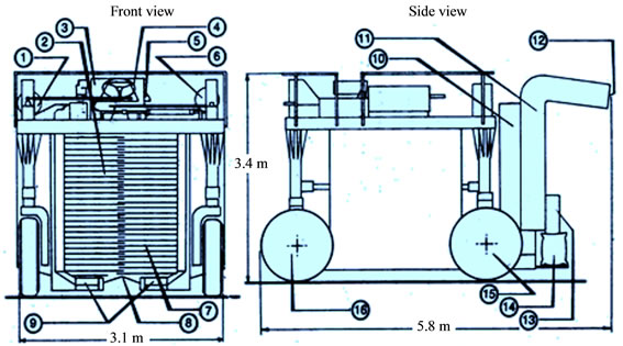
Figure 1. Self-propelled coffee harvester scheme. Legend: 1. Diesel tank; 2. vibrators; 3. diesel engine; 4. command post; 5. operational controls; 6. hydraulic system; 7. vibrators; 8. collectors; 9. carriers; 10.elevator; 11. cleaning system; 12. dirties output; 13. harvested coffee; 14.coffee bagging; 15. rear wheels; 16. front wheel.
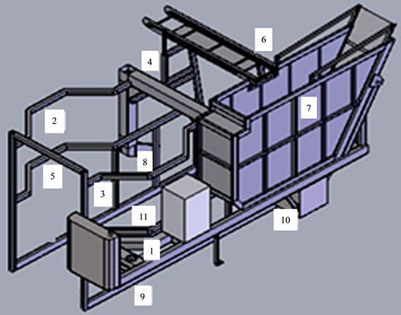
Figure 2. CAD model isometric view for the original structure. Legend: 1. Engine frame; 2. Body right side; 3. Body left side; 4. Main beam; 5. Body front end; 6. Body rear end; 7. Coffee reservoir; 8. Right rear wheel; 9. Guide wheel; 10 left rear wheel; 11. Fuel tank.
In order to simulate different conditions of working in a coffee harvester machine, two situations had been used according to the following situations:
• Design A: full coffee reservoir and rear wheels aligned;
• Design B: full coffee reservoir and rear wheels misaligned.
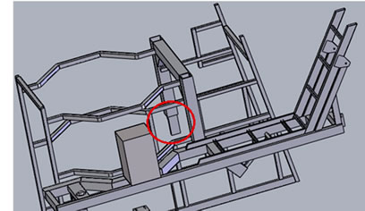
The use of aligned and misaligned rear wheels in this study is justified by the focus on a new structural design of harvester coffee machines in order to provide a better efforts distribution through an unconventional rear wheels configuration using finite element resources. Figure 3 shows CAD models for coffee harvester structures complaining situations A and B (it is noted that some components were removed from the original design for a model simplifications during the simulations).
The material used was ASTM A36 steel for the structural parts and AISI 304 stainless steel for the fuel tank which the main properties are shown in the Table 1.
External loads acting in the machine structure were defined based on the own weight of each component and substances densities (Table 2). In addition to the substances weight, simulations were performed taking into account the weight of the components according to Table 3. Furthermore, clamping loads were defined according to attachment points of each component in analysis.
 (a)
(a)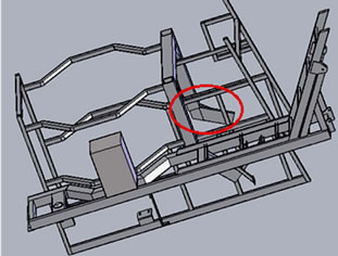 (b)
(b)
Figure 3. Coffee harvester structure CAD models for (a) rear wheels aligned and (b) rear wheels misaligned.

Table 1. Material properties of structural parts and fuel tank.
Table 2. Densities of substances.
Table 3. Loads applied in the machine structure.
The mesh of machine structural parts was defined as triangular element type with ranging size between 1.2 mm and 47.0 mm which generated 35121 nodes. Figure 4 represents a portion of the generated mesh for the machine with rear wheels aligned.
3. Results and Discussion
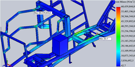
The last step was to simulate static analysis of the harvester machine in order to plot VM stress and displacement for the structure with rear wheels aligned and misaligned. Figure 5 shows the maximum VM stress for both situations.
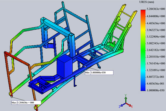
Figure 6 shows the maximum displacement for each situation (displacement results for the machine with rear wheels aligned and rear wheels misaligned).
Figure 7 shows graphics that compares results of maximum VM stresses and average VM stresses.
Even though design B has presented highest maximum VM stresses (Figure 7(a)), it was observed lowest average VM stresses (Figure 7(b)) for the same design compared to design A, showing better stress distribution in the structure with rear wheels misaligned (design B) with 4,5% reduction of average VM stresses.
Figure 8 shows values of maximum displacements in design A compared to design B, which proved better performance of structure with rear wheels misaligned in terms of design.
In order to certify which situation would be the suitable design option, it was analyzed maximum VM stress compared to the average stress in each structural component for both situations (design A and design B) as shown in Figures 9 and 10.
Focusing on wheels zones stresses (Figures 9 and 10) it is noted, in both cases, that:
• The structure of left wheel presented higher values of maximum VM stress and the highest value of average VM stress compared to the other structural parts as result of the full coffee reservoir weight above the rear left wheel.
• The guide wheel showed low values of maximum VM stress and average stress even comparing with other structural parts, except for the body rear end.
• Average VM stress values for the misaligned wheels design were lower in 7 of 10 analyzed structural parts compared to the wheels aligned design.
• The structure of right wheel for design B (rear wheels misaligned) reduced by half the maximum VM stress when compared to design A (rear wheels aligned).
Based on that, it was certified that misaligned wheels design presented better performance than aligned wheels design in terms of stresses and displacements. The coffee harvester machine with misaligned wheels was built and started working without any structural fail as shown in Figure 11.
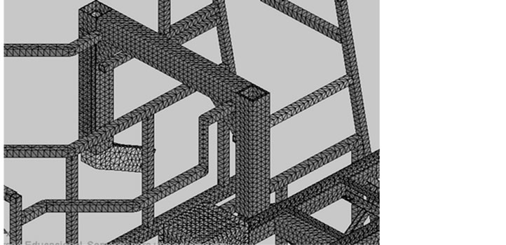
Figure 4. Portion of generated mesh for the harvester machine with rear wheels aligned.
 (a)
(a)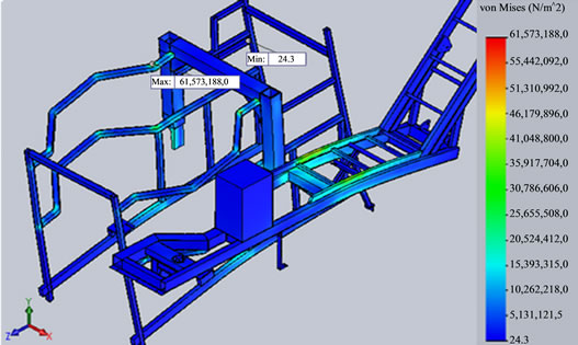 (b)
(b)
Figure 5. (a) VM stress results for the rear wheels aligned; (b) VM stress results for the rear wheels misaligned.
 (a)
(a)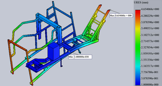 (b)
(b)
Figure 6. (a) Displacement results for the machine with rear wheels aligned; (b) Displacement results for the machine with rear wheels misaligned.
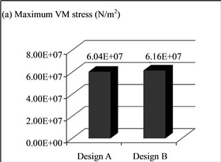
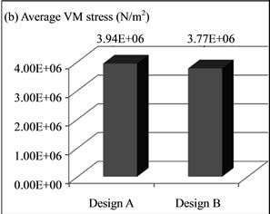
Figure 7. (a) Maximum VM Stresses; (b) Average VM Stresses.
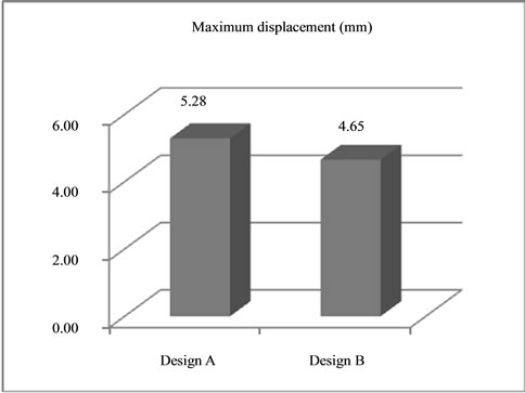
Figure 8. Maximum displacement for design A and design B.
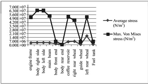
Figure 9. Maximum VM stress vs. average stress for the rear wheels aligned.
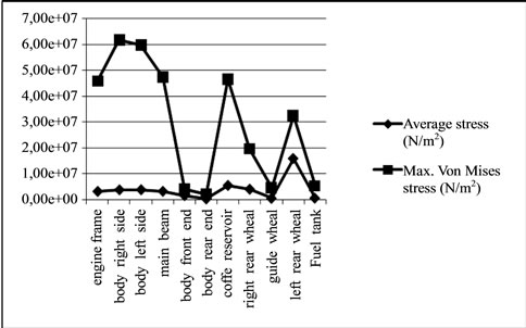
Figure 10. Maximum VM stress vs. average stress for the rear wheels misaligned.
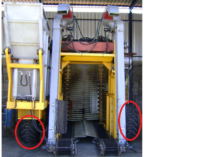
Figure 11. Coffee harvester machine with misaligned rear wheels in operation.
4. Conclusions
In the presented paper, analysis of VM stress and displacement were supported by static finite element analysis. This paper had no intention to show any dynamic effects of a coffee harvester machine and this can be considered a limitation of the presented work. Also only structural parts were analyzed in this study as result of FEM timing consumed if finishing parts were added.
It was compared two different designs of a coffee harvester structures with rear wheels aligned and misaligned. FEM results showed maximum displacement in the structure with rear wheel misaligned (4.65 mm placed in the rear end structure) lower than the model with rear wheels aligned (5.28 mm placed in the front end structure) which represented a difference of 11.9% providing better machine structural equilibrium. Maximum VM stress results for the machine structure with rear wheels misaligned was 6.16 × 10⁷ N/m2 against 6.04 × 10⁷ N/m2 for the machine structure with rear wheels aligned, which represented a difference of 1.9%. Even though design with rear wheels misaligned presented highest maximum VM stresses, it was observed reduction of 4.5% in terms of average VM stresses.
Going in deep in each structural component for VM stress results, it was observed that the average stresses for the misaligned wheels design were lower in 7 of 10 analyzed parts compared to the wheels aligned design. In addition, the structure of right wheel for design with rear wheels misaligned reduced by half of the maximum VM stress when compared to design with rear wheels aligned. Based on FEM results, it was certified that the structure with rear wheels misaligned was the best design concept. It was confirmed in the field after a coffee harvester built with misaligned rear wheels with no fail during operation.
Acknowledgements
The authors would like to thanks the company VETOR for technical support and financial resources and CAPES for financial support for the project research.
References
- Thiyagarajan, R., Kathirvel, K. and Jayashree, G.C. (2013) Ergonomic Intervention in Sugarcane Harvesting Knives. African Journal of Agricultural Research, 8, 574-581.
- Huang, T., Kong, C.W., Guo, H.L., Baldwin, A. and Li, H. (2007) A Virtual Prototyping System for Simulating Construction Processes. Automation in Construction, 16, 576-585. http://dx.doi.org/10.1016/j.autcon.2006.09.007
- Han, J.N., Cho, N.J., Chae, S.W. and Choi, Y. (2010) Stress Analysis of Ventilated Brake Discs Using the Finite Element Method. International Journal of Automotive Technology, 11, 133-138. http://dx.doi.org/10.1007/s12239-010-0018-0
- He, B., Wang, S. and Gao, F. (2010) Failure Analysis of an Automobile Damper Spring Tower. Engineering Failure Analysis, 17, 498-505. http://dx.doi.org/10.1016/j.engfailanal.2009.09.010
- Petracconi, C.L., Ferreira, S.E. and Palma, E.S. (2010) Fatigue Life Simulation of a Rear Tow Hook Assembly of a Passenger Car. Engineering Failure Analysis, 17, 455-463. http://dx.doi.org/10.1016/j.engfailanal.2009.09.002
- Wang, X. and Zhang, X. (2010) Simulation of Dynamic Cornering Fatigue Test of a Steel Passenger Car Wheel. International Journal of Fatigue, 32, 434-442. http://dx.doi.org/10.1016/j.ijfatigue.2009.09.006
- Magalhaes, R.R., Fontes, C.H. and Melo, S.A.B.V. (2012) Failure Analysis and Design of a Front Bumper using Finite Element Method along with Durability and Rig Tests. International Journal of Vehicle Design, 60, 71-83. http://dx.doi.org/10.1504/IJVD.2012.049158
- Tang, C.Y., Chan, W. and Tsui, C.P. (2010) Finite Element Analysis of Contact Pressures between Seat Cushion and Human Buttock-Thigh Tissue. Engineering, 2, 720-726. http://dx.doi.org/10.4236/eng.2010.29093
- Zienkiewicz, O.C. (1970) The Finite Element Method: From Intuition to Generality. Applied Mechanics Reviews, 23, 249-256.
- Knight, C.E. (1993) The Finite Element Method in Mechanical Design. Pws-Kent, Boston.
- Magalhaes, A.C., Teixeira, M.M., Couto, S.M. and Resende, R.C. (2006) Modeling of Pneumatic Machine Collector of Coffee Fruits on Yard Using Finite Elements Analysis. Engenharia Agricola, 26, 483-492.
- Celik, H.K., Rennie, A.E.W. and Akinci, I. (2011) Deformation Behaviour Simulation of on Apple under Drop Case by Finite Element Method. Journal of Food Engineering, 104, 293-298. http://dx.doi.org/10.1016/j.jfoodeng.2010.12.020
- Nilnonta, W., Thepaa, S., Janjaib, S. and Kasayapananda, N. (2012) Finite Element Simulation for Coffee (Coffea Arabica) Drying. Food and Bioproducts Processing, 90, 341-350.
- Li, Z., Li, P., Yang, H. and Liu, J. (2013) Internal Mechanical Damage Prediction in Tomato Compression Using Multiscale Finite Element. Journal of Food Engineering, 116, 639-647. http://dx.doi.org/10.1016/j.jfoodeng.2013.01.016
- Ferraz, G., Silva, F.M., Alves, M.C., Bueno, R.L. and Costa, P. (2012) Geostatistical Analysis of Fruit Yield and Detachment Force in Coffee. Precision Agriculture, 13, 76-89. http://dx.doi.org/10.1007/s11119-011-9223-8