Materials Sciences and Applications
Vol.06 No.06(2015), Article ID:56900,10 pages
10.4236/msa.2015.66052
Numerical Analysis of Stresses on Layer-by-Layer Basis in FML Composite Cylinder Subjected to External Hydrostatic Loading
B. G. Sumana1*, H. N. Vidya Sagar2, K. V. Sharma2, M. Krishna3
1Research Scholar, Department of Mechanical Engineering, University Visvesvaraya College of Engineering, Bangalore, India
2Department of Mechanical Engineering, University Visvesvaraya College of Engineering, Bangalore, India
3Department of Mechanical Engineering, R V College of Engineering, Bangalore, India
Email: *sumogh76.gec@gmail.com
Copyright © 2015 by authors and Scientific Research Publishing Inc.
This work is licensed under the Creative Commons Attribution International License (CC BY).
http://creativecommons.org/licenses/by/4.0/


Received 13 April 2015; accepted 1 June 2015; published 4 June 2015
ABSTRACT
The aim of the research work was to numerically investigate the residual stresses induced between the layers of fiber metal laminate (FML) cylinder (glass/epoxy reinforced aluminum laminates) under buckling hydrostatic loading. For the analysis of buckling behavior of FML cylinders, various fiber orientations such as 0/90˚, 60/30˚, ±45˚ and ±55˚ and different FRP thickness of 1, 2, and 3 mm were considered. The aluminum cylinder of inner diameter 80 mm, length 800 mm and wall thickness 1 mm was modeled with SHELL281 element type and a total of 1033 elements were used for computing the induced residual stresses between the layers. The results show that magnitude of residual stresses between the layers decreased along the thickness from outer layer towards the inner layer in sine wave form. The maximum residual Von-Mises stress was at inner aluminum layer while the maximum residual radial stress was at the outermost layer of FML cylinder due to the inward pressure. Among all types of FML cylinder 0/90˚ fiber oriented FML cylinder exhibited the least radial stress and a maximum Von-Mises stress along the FRP thickness.
Keywords:
FML Cylinder, External Hydrostatic Loading, Residual Stress, Von-Mises Stress, Radial Stress

1. Introduction
Fiber Metal Laminate (FML) composite cylinders possess superior properties of both metals and fibrous composite materials making them most suitable for oil and gas storage, transportation, high pressure working conditions etc. [1] . During the manufacturing process of FML cylinders using filament winding method, residual stresses are induced in between the layers of the composite cylinder due to mismatch of the physical, mechanical and chemical properties of the matrix and reinforcement [2] [3] . These residual stresses induced by different means in the layers increase the mechanical property of the composite cylinder by increasing wear and corrosion resistance and also prevent propagation of fatigue cracks [4] . In certain circumstances they prove detrimental resulting in warping, undesirable distortion, fiber-matrix cracking and dimensional instability leading to premature failure [2] . Also, residual stresses such as radial stress, hoop stress etc. generated under various loading conditions are important factors in the design of FML composite cylinders [5] [6] .
The prediction of stress distributions in the composite cylindrical structures is complicated due to the geometrical curvature, material anisotropy and discontinuity in the structures [7] . Several experimental [2] , analytical and numerical studies have been performed to determine the behavior of induced residual stresses in composite cylinders. Experimental techniques such as layer removal method, ring slitting method, laser speckle technique, strain gauge method etc. were developed to predict residual stresses in composite cylinders [4] [8] . But these methods encountered problems such as destruction of the specimen, non-suitability to anisotropic composites, precision requirement etc. [9] . Various input parameters such as basic fiber properties, fiber orientations, number of layers, geometric and loading parameters associated with isotropic cylinders prohibits a purely experimental approach [10] . Two theoretical approaches: the classical laminates theory [5] and the theory of elasticity [6] used to investigate the behavior of stresses and strains in pure orthotropic composite cylinders lacked interfacial continuity parameters that are required for multi-layered cylinders [7] . Numerical analysis based on Lekhnitskii approach was performed for composite cylinders but using only the homogenization method [7] .
FML cylindrical structures are more complex than composite cylinders. As per the authors no research work has been focused earlier on buckling studies of FML cylinder using numerical approach to predict layer-by-layer stress distribution. The objective of this study was to evaluate different residual stresses such as Von-Mises stress and radial stress layer-by-layer post buckling in the FML cylinder due to external hydrostatic pressure using ANSYS.
2. Experimental Studies
The FML composite cylinders were manufactured using filament winding machine. Aluminum tube of inner diameter 80 mm, thickness 1 mm and length 800 mm was used as metallic liner on which glass fibers reinforced with epoxy resin was wound at different orientations and thickness. A total of twelve FML cylinders were prepared with fibers wound at 0/90˚, 60/30˚, ±45˚ and ±55˚ orientations and thickness of FRP maintained at 1, 2 and 3 mm. The cured FML cylinders were subjected to external hydrostatic loading in an in-house buckling tester which is shown in Figure 1. The testing chamber can apply pressure upto 30 MPa, which is equal to the water pressure at a depth of 3000 m under the sea. A high pressure pump was used to supply and regulate the hydrostatic pressure. The applied external pressure was increased in steps of 0.2 MPa till failure occurred due to buckling. Strain gauges were mounted along the axis and circumference of the FML cylinder to measure deformation during the process of buckling.
The experimental results determined the critical buckling pressure and the corresponding deformation. These results were validated numerically as shown in Figure 2. The comparison of experimental results and numerical results showed a deviation within 10%. This was considered satisfactory due to the possible geometric, material and loading uncertainties between physical tests and numerical simulation. The experimental determination of residual stresses in individual layer of FRP is complex in nature; hence the above FE analysis was extended to determine the stress in individual layers for a given material, geometry and loading condition.
3. Numerical Analysis
The simulation has been carried out by using ANSYS 14.5 finite element package. The flow chart shown in Figure 3 describes the steps involved in using the software for Eigen buckling analysis and to determine the stress in individual layers of FML composite cylinder. A detailed description of the steps is described in the following section.
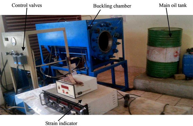
Figure 1. Experimental setup to test buckling due to hydrostatic pressure in FML cylinders.
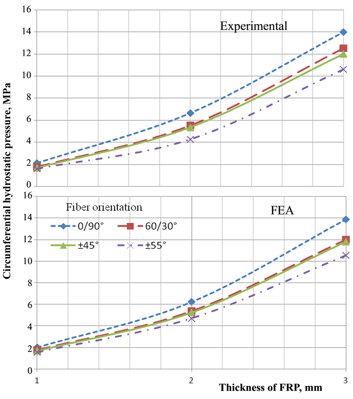
Figure 2. Validation of FE results with experimental values of FML cylinder under hydrostatic.
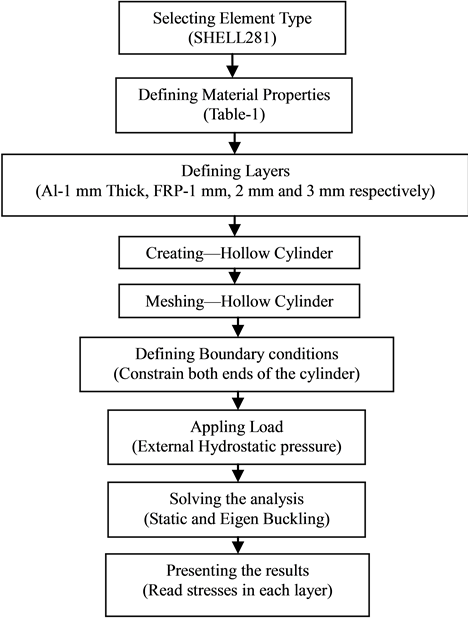
Figure 3. Flow chart of numerical analysis for predicting the residual stresses in between the layers.

Table 1. Material properties of Aluminum (Al 6061-T6) and Glass/Epoxy composite.
3.1. Element Type and Material Properties
The element type used was SHELL281 for both Al metallic liner and FRP. SHELL281 is suitable for analyzing moderately-thick shell structures. It has eight nodes with six degrees of freedom at each node: translations in the x, y, and z axes, and rotations about the x, y, and z-axes. This element may be used for layered applications for modeling composite shell structures. The mechanical properties needed are modulus of elasticity (E) and Poisson’s ratio (υ) for linear isotropic material i.e., aluminum and orthotropic properties for FRP. The mechanical properties of Al 6061 and glass-epoxy composite material are listed in Table 1.
3.2. Modeling and Meshing
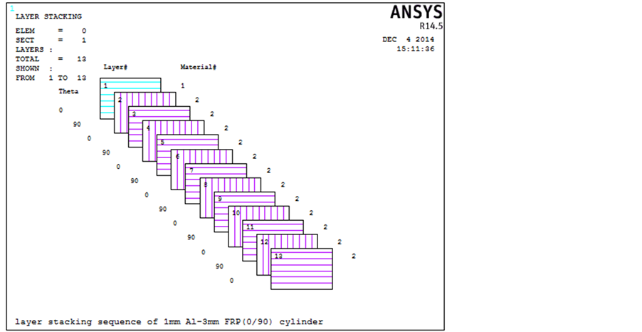
Al metallic liner of 1 mm thickness is input as one layer, on which FRP of 0.25 mm thickness with respective winding angle is considered for the finite element analysis. The layer stacking sequence of 3 mm FRP wound on 1 mm Al metallic liner is shown schematically in Figure 4(a). A hollow cylinder was created using the option of solid cylinder and then deleting the volume and areas. This was done in order to maintain same displacement of the interface. The composite cylinder was then meshed free as shown in Figure 4(b). The maximum number of nodes was 3145 and maximum deformation was observed around node 1208 respectively.
3.3. Constraints and Loading
The ends of the composite cylinder were constrained along all degrees of freedom, as shown in Figure 4(c). An external pressure of p = −1 was applied on the external surfaces of composite as shown in Figure 4(d). Static
 (a)
(a)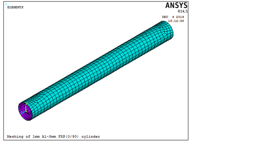 (b)
(b)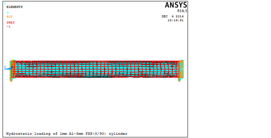 (c)
(c)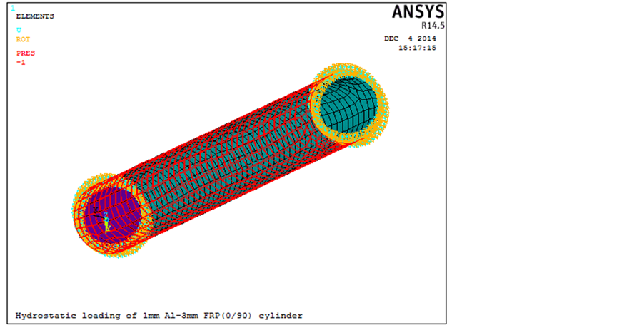 (d)
(d)
Figure 4. Finite element model of FML cylinder to compute residual stresses: (a) Stacking sequence; (b) Meshing; (c) Boundary conditions; (d) Hydrostatic loading.
analysis and Eigen buckling analysis using Block Lanczos extraction method were performed in sequence to obtain the critical buckling pressure. Static buckling was performed to determine the pre-buckling deformation. The linear Eigen value buckling analysis was used to determine buckling load―initial/critical load at which a structure becomes unstable and buckled mode shapes―the characteristic shape associated with a structure’s buckled response [1] . It only predicts the pre-buckling deformation, but does not solve the magnitude of deformation post buckling [5] . At hydrostatic buckling pressure, stresses such as radial stress and Von Mises stress in each layer were noted to determine the damage mode of failure in fibers.
4. Results and Discussion
FML composite cylinders of 0/90˚, 60/30˚, ±45˚ and ±55˚ fiber orientations and thickness of FRP 1, 2 and 3 mm subjected to external hydrostatic pressure exhibit buckling at bifurcation point. Various stresses such as Von Mises stress, hoop stress and radial stress influence the buckling behaviour of FML composite cylinder. The magnitude of Von-Mises stress and radial stress in each layer of FML composite cylinder was investigated. The inner Al metallic liner of thickness 1 mm was considered as layer 1 and the next subsequent layers were that of FRP with each layer of thickness 0.25 mm. Since the loading was external hydrostatic pressure, the results were interpreted from outermost fiber layers “A” to the inner Al layer.
Under external hydrostatic loading, the magnitude of stress in Al layer is maximum at the outer surface and minimum at the inner surface with linear decrease in the wall of the cylinder. This behaviour remains same for all the FML composite cylinders irrespective of FRP thickness and fiber orientation. Hence, it was not indicated in the graphs. Only the magnitudes of maximum stress at the outer surface of Al cylinder were represented. The value of stress in each layer was investigated at the hydrostatic buckling pressure of the FML composite cylinder.
The fabrication of FML composite cylinder by filament winding process induces compressive stresses in the inner Al metallic liner and tensile stresses in the outer fibers. The external hydrostatic pressure induces compressive stresses on the circumference of the FML composite cylinder. The FML composite cylinder with 0/90˚ fiber orientation experienced combined longitudinal and transverse compression, while FML composite cylinders with 60/30˚, ±45˚ and ±55˚ fiber orientation experienced off-axis compression.
Figure 5 shows the graph of Von-Mises stresses in each layer of FML composite cylinder. The curves exhibit two types of behaviour such as (a) sinusoidal magnitude of stress as indicated in region “A” and (b) maximum stress in the outer layer of Al tube as represented in region “B”.
All the considered FML hollow shafts exhibit zig-zag mode of stress in FRP layers with decreasing magnitude from outer to inner layers as shown in region “A”. Layers with 0˚ fiber orientation showed higher value of stress. As the orientation of fiber increased from 0˚ to 90˚, the value of stress decreased with minimum value of stress in layer having fibers oriented at 90˚. Higher stiffness in circumferential direction leads to higher buckling load and least amount of stress [11] . The peak-to-peak magnitude (waviness) of stress was higher in shafts with 0/90˚ and 60/30˚ fiber orientation, while the magnitude of stress remained almost consistent in shafts with ±45˚ and ±55˚ fiber orientation, due to symmetric off-axis loading. The sinusoidal magnitude of stress was due to change in fiber orientation along alternate layers of the cylinder.
As observed in region “B”, the magnitude of Von-Mises stress was higher in Al layer. This behavior was expected as the liner forced into compression by the fibers during the winding process tries to return elastically to their original size [12] . The fibers operate in a tension-compression mode while the Al liner operates elastically from compression to compression [12] resulting in induced stresses attaining maximum value.
The magnitude of Von-Mises stress decreased with increase in fiber orientation from 0˚ to 90˚. The orientation of fibers at 90˚ induces maximum circumferential stiffness, thus reducing the stress in those layers. As the thickness of FRP was increased, the magnitude of stress from outer layer to inner layer suppressed due to the viscoelastic property of FRP [13] .
Figure 6 shows the graph of radial stresses in each layer of FML composite cylinder at its respective critical (maximum) hydrostatic buckling pressure. The curves showed three types of behaviour, viz., (a) decreasing magnitude of stress in region “B”, (b) consistent magnitude of stress in region “C”, and (c) increase in magnitude of stress in region “D”. All the FML composite cylinders exhibited maximum value of radial stress at the outer fiber layer due to external loading condition.
In FML composite cylinder of 1 mm FRP thickness, only two regions, region “B and region “D” were observed. A drastic decrease in magnitude of stress was observed in region “B”. The slope of stress in region “B” can be compared to be similar to the slope of stress in isotropic Al cylinder, since the thickness of Al and FRP being same. In region “D”, the magnitude of stress increased due to higher stress at the outer surface of Al cylinder as compared to stress in inner layer of FRP. In a hybrid composite, the low strain (LS) material fails earlier but the high strain (HS) material which has a higher failure strain can carry the load so that overall integrity is maintained [14] .
In FML composite cylinders of FRP thickness 2 and 3 mm, region “B” exhibited a sinusoidal decrease in magnitude of stress at the outer layers of FRP. This sinusoidal behaviour was due to the circumferential stiffness of fibers oriented at 90˚ and axial stiffness of fibers orientated at 0˚ [11] . As the fiber orientation decreased from 90˚ to 0˚, the circumferential stiffness decreased while the axial stiffness increased. This resulted in reduced waviness of FML composite cylinders of 60/30˚, ±45˚ and ±55˚ fiber orientation. Also, the magnitude of sinusoidal
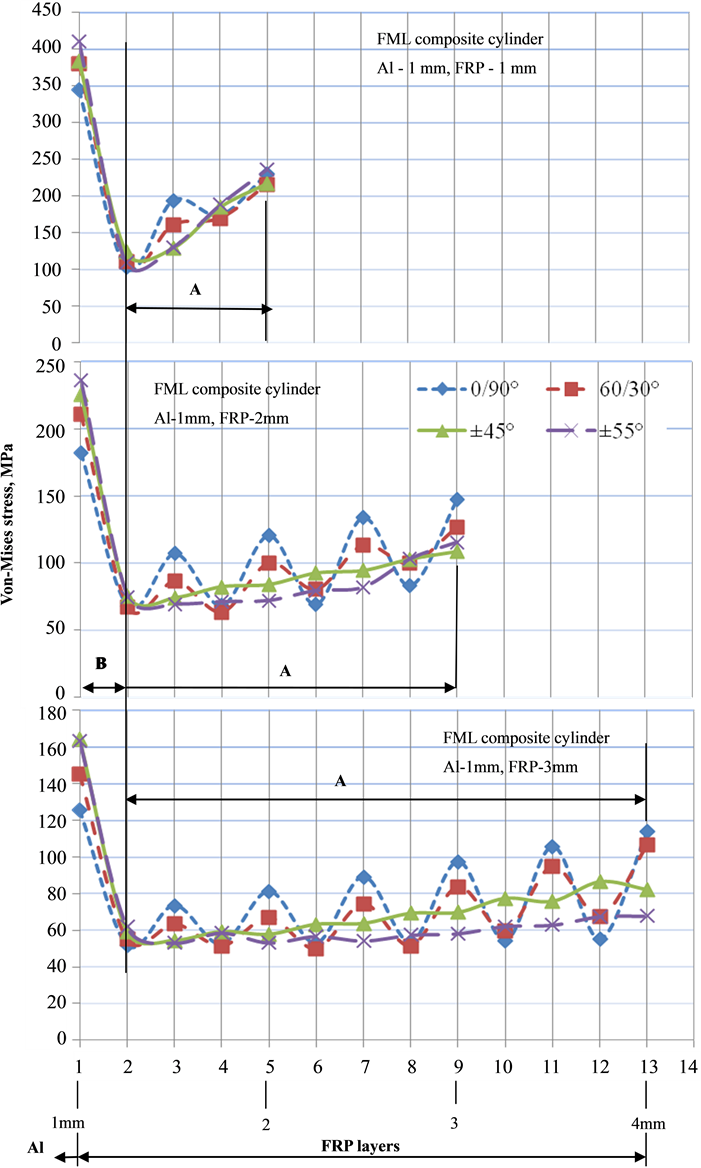
Figure 5. Effect of fiber orientation and FRP thickness on Von-Mises stresses in FML composite cylinders.
behaviour reduced as hydrostatic pressure approached the inner layers. The viscoelastic property of FRP suppresses the magnitude of stress from outer towards inner layers [13] . This led to increased consistence in magnitude of stress at the inner layers as the thickness of FRP increased. Further, due to higher stress at outer surface of Al cylinder as compared to stress in inner layer of FRP, the magnitude of stress increased, as indicated in region “D”.
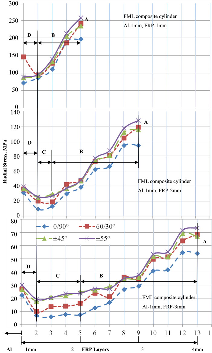
Figure 6. Variation of radial stresses due to fiber orientation and FRP thickness in FML composite cylinders.
The stress in the FRP layers at which the initial buckling occurred depends on the fiber failure strength, fiber orientation and loading angle. After initial buckling, the path of stress distribution in FRP can be attributed to different damage modes such as fragmentation/multiple fractures in region “B” and dispersed delamination in region “C” [14] . The buckling in fibers reduces the stiffness of FRP, resulting in overall strength reduction of FML composite cylinder.
Irrespective of FRP thickness, FML composite cylinder with 0/90˚ fiber orientation possessed least stresses indicating higher circumferential stiffness. As the orientation of fiber decreased from 90˚ to 0˚, the magnitude of induced stresses increased. The magnitude of sinusoidal behaviour was high in cross-ply (0/90˚, 60/30˚ and ±45˚ fiber orientation) FML composite cylinders, while it remained nearly consistent in angle-ply (±55˚) FML composite cylinder, resulting in maximum induced radial stress. The stresses in FML composite cylinders with ±45˚ and ±55˚ fiber orientation were observed to be similar due to symmetric off-axis loading condition. Research by [13] confirms that radial stresses decrease to certain values and then increase in pure material cylinder.
As the thickness of FRP increased, the magnitude of stress in each layer and in overall cylinder decreased, due to increased stiffness in the cylinder [15] . In FML cylinder of FRP thickness 1 and 2 mm, the outer most FRP layer had maximum stress, due to external loading. But in FML cylinder of FRP thickness 3 mm, the layer next to the outer most layer possessed maximum stress. This may be due to the tensile residual stresses induced during filament winding and compressive stresses induced during loading.
5. Conclusions
FML composite cylinders with 0/90˚, 60/30˚, ±45˚ and ±55˚ fiber orientation and FRP thicknesses of 1, 2 and 3 mm were subjected to external hydrostatic loading. From the numerical analysis performed to determine the residual stresses in individual layers, the following conclusion can be summarized:
・ Layers with 0˚ fiber orientation showed higher value of residual Von-Mises stress, while layers with 90˚ fiber orientation possessed least magnitude, due to stiffness being higher in circumferential direction.
・ The waviness in magnitude of Von-Mises stress was higher in FML composite cylinders with 0/90˚ and 60/30˚ fiber orientation; while the magnitude remained consistent in FML composite cylinders with ±45˚ and ±55˚ fiber orientation, due to symmetric off-axis loading.
・ In all the considered FML composite cylinders, maximum value of residual radial stress was at the outer layer due to external loading condition.
・ FML composite cylinders of 1 mm FRP thickness exhibited two regions of radial stress, as the thicknesses of Al metallic liner and FRP were the same.
・ FML composite cylinders of 2 and 3 mm FRP thickness exhibited three regions of radial stress behavior.
The Von-Mises stress and radial stress decreased with increase in thickness of FRP for FML composite cylinders of considered fiber orientation.
References
- Nowak, T. and Schmidt, J. (2014) Prediction of Elasto-Plastic Behavior of Pressurized Composite Reinforced Metal Tube by Means of Acoustic Emission Measurements and Theoretical Investigation. Composite Structures, 118, 49-56. http://dx.doi.org/10.1016/j.compstruct.2014.07.015
- Shokrieh, M.M. (2014) Residual Stresses in Composite Materials. Woodhead Publishing Limited, Narmak, xix-10.
- Abou Msallem, Y., Jacquemin, F., Boyard, N., Poitou, A., Delaunay, D. and Chatel, S. (2010) Material Characterization and Residual Stresses Simulation during the Manufacturing Process of Epoxy Matrix Composites. Composites Part A: Applied Science and Manufacturing, 41, 108-115. http://dx.doi.org/10.1016/j.compositesa.2009.09.025
- Rossini, N.S., Dassisti, M., Benyounis, K.Y. and Olabi, A.G. (2012) Methods of Measuring Residual Stresses in Components. Materials and Design, 35, 572-588. http://dx.doi.org/10.1016/j.matdes.2011.08.022
- Parnas, L. and Katrice, N. (2002) Design of Fiber-Reinforced Composite Pressure Vessels under Various Loading Conditions. Composite Structures, 58, 83-95. http://dx.doi.org/10.1016/S0263-8223(02)00037-5
- Tutuncu, N. and Winckler, S.J. (1993) Stresses and Deformations in Thick-Walled Cylinders Subjected to Combined Loading and Temperature Gradient. Journal of Reinforced Plastic and Composite, 12, 198-209. http://dx.doi.org/10.1177/073168449301200206
- Sun, X.S., Tan, V.B.C., Chen, Y., Tan, L.B., Jaiman, R.K. and Tay, T.E. (2014) Stress Analysis of Multi-Layered Hollow Anisotropic Composite Cylindrical Structures Using the Homogenization Method. Acta Mechanica, 225, 1649- 1672. http://dx.doi.org/10.1007/s00707-013-1017-9
- Seif, M.A., Khashaba, U.A. and Rojas-Oviedo, R. (2007) Residual Stress Measurements in CFRE and GFRE Composite Missile Shells. Composite Structures, 79, 261-269. http://dx.doi.org/10.1016/j.compstruct.2006.01.002
- Williams, J.G., Hodgkinson, J.M. and Gray, A. (1981) The Determination of Residual Stresses in Plastic Pipe and Their Role in Fracture. Polymer Engineering & Science, 21, 822-828. http://dx.doi.org/10.1002/pen.760211304
- Spagnoli, A., Elghazouli, A.Y. and Chryssanthopoulos, M.K. (2001) Numerical Simulation of Glass-Reinforced Plastic Cylinders under Axial Compression. Marine Structures, 14, 353-374. http://dx.doi.org/10.1016/S0951-8339(00)00008-3
- Goldfeld, Y., Arbocz, J. and Rothwell, A. (2005) Design and Optimization of Laminated Conical Shells for Buckling. Thin-Walled Structures, 43, 107-133. http://dx.doi.org/10.1016/j.tws.2004.07.003
- Kabir, M.Z. (2000) Finite Element Analysis of Composite Pressure Vessels with a Load Sharing Metallic Liner. Composite Structures, 49, 247-255.
- Afshar, R., Bayat, M., Lalwani, R.K. and Yau, Y.H. (2011) Elastic Behavior of Glass-Like Functionally Graded Infinite Hollow Cylinder under Hydrostatic Loads Using Finite Element Method. Materials and Design, 32, 781-787. http://dx.doi.org/10.1016/j.matdes.2010.07.023
- Jalalvand, M., Czél, G. and Wisnom, M.R. (2015) Damage Analysis of Pseudo-Ductile Thin-Ply UD Hybrid Composites―A New Analytical Method. Composites Part A: Applied Science and Manufacturing, 69, 83-93. http://dx.doi.org/10.1016/j.compositesa.2014.11.006
- Kim, D. and Chaudhuri, R.A. (2007) Effect of Thickness on Buckling of Perfect Cross-Ply Rings under External Pressure. Composite Structures, 81, 525-532. http://dx.doi.org/10.1016/j.compstruct.2006.09.015
NOTES

*Corresponding author.