Materials Sciences and Applications
Vol.5 No.10(2014), Article
ID:49387,5
pages
DOI:10.4236/msa.2014.510073
Influence of Fe Content on Tool Galling in Ironing Aluminum Beverage Cans
Aleksey Vladimirovich Andrianov1, Elena Gennadievna Kandalova2, Evgeniy Vladimirovich Aryshensky3
1FRP Heat Treatment Department, ZAO “Alcoa SMZ”, Samara, Russia
2Technological Development Department, ZAO “Alcoa SMZ”, Samara, Russia
3Industrial Engineering Department, Samara State Aerospace University, Samara, Russia
Email: Aleksey.Andrianov@alcoa.com, Elena.Kandalova@alcoa.com, ar.evgenii@yandex.ru
Copyright © 2014 by authors and Scientific Research Publishing Inc.
This work is licensed under the Creative Commons Attribution International License (CC BY).
http://creativecommons.org/licenses/by/4.0/


Received 4 June 2014; revised 8 July 2014; accepted 30 July 2014
ABSTRACT
Insoluble constituents in 3104 alloy for beverage cans manufacturing play an important role in deep ironing process. This paper studies the effect of Fe content in the alloy on volume fraction of the constituents Al6(Fe, Mn)3 and Al12(Fe, Mn)3Si and its influence on ironing die pickup. It is shown that with Fe content increase, the amount of these constituents rises that helps prevent tool galling. Trials made at a can plant showed less ironing die changeovers at bodymakers. The optimum Fe content for aluminum can production can be considered between 0.47% and 0.53% that corresponds to 2.0% - 2.3% of insoluble constituent volume fraction. Greater amounts than this cause problems with excessive constituent particle formation and earing; smaller amounts result in increased ironing die galling.
Keywords:3104 Alloy, Ironing Aluminum, Tool Galling, Fe Content, Insoluble Constituents

1. Introduction
Nowadays, 3104 alloy is widely used in the manufacture of drawn and ironed beverage cans. One of the key factors for successful deep drawing and ironing is galling resistance. Galling is accumulation of mixed aluminium and aluminium oxides pick-up on tooling performing the ironing. It results in scoring on can side walls. It was shown [1] that achieving a specific phase composition and microstructure can help prevent die pickup. During casting and further solidification of 3104 ingot, the main insoluble constituent that forms is Al6(Fe, Mn), along with small amounts of Al12(Fe, Mn)3Si and soluble Mg2Si constituents [2] . During subsequent homogenization, the Al6(Fe, Mn) constituent is partially transformed into Al12(Fe, Mn)3Si, and Al12(Fe, Mn)3Si dispersoids precipitate from supersaturated solid solution. It was thought that these particular dispersoids (which had sizes below 1 μm) accounted for abrading the tooling, but it was later demonstrated that this function was performed by larger Al6(Fe, Mn) and Al12(Fe, Mn)3Si constituent particles which were harder than aluminium 25 and 44 times correspondingly. To provide resistance to tool galling, the volume fraction of the constituents should be controlled [1] [3] [4] .
As well as volume fraction, the size of Fe-containing constituents is also important. To reduce tool galling, the optimum size of the constituents should be between 2 to 15 μm [1] . If the constituent size exceeds 15 μm, the risk of can tear-off during drawing increases dramatically. Other studies have shown that 25 μm is the critical size of Fe-containing constituents in terms of can tear-off rate [5] . Such a difference in the critical constituent size is explained by differences in the specifics of the can ironing process and lubrication conditions. It was also demonstrated that to prevent formation of large Al6(Fe, Mn) particles, the total Fe + Mn content should not exceed 1.7% [6] .
Thus, insoluble constituents provide resistance to tool galling and contribute to anisotropy control. The objective of the present study was to establish the effects of Fe content on the volume fraction and sizes of Al6(Fe, Mn) and Al12(Fe, Mn)3Si constituents, and to find out the optimum based number of changeovers of ironing dies at bodymakers, which represents the tool galling rate, and tear-off rate at a can plant.
2. Experimental
Trial lots of 3104 alloy ingots were cast with different Fe content (Table 1). Each lot consisted of 6 - 12 ingots In the lot with maximum Fe content, Cu content was reduced from 0.19% - 0.20% to 0.15% - 0.16% and Si content was slightly increased to compensate for the possible negative Fe content impact on 45˚ earing [7] . The commercial composition of 3104 alloy was used as a baseline to determine the content of Fe, Si and Cu in the trial lots.
As-cast ingot microstructure was examined on head and butt slices from the rolling face to 60 mm depth below it and at 1/4 and 1/2 ingot thickness using optical microscopy.
The coils were rolled by the standard plant route to the finish gauge 0.250 mm. Microstructure of hot-rolled samples was examined for recrystallization. The size and volume fraction of Al6(Fe, Mn) and Al12(Fe, Mn)3Si constituents in the finish gauge samples were determined with an EDX-equipped JEOL 6390A SEM. The coldrolled coils were tested for ultimate tensile strength, yield strength, postbake strength (yield strength after anneal simulating drying conditions in can manufacturing) and earing.
The experimental coils were processed at a can-making plant. The following key parameters were evaluated: number of changeovers of ironing dies at bodymakers and tear-off rate per 100,000 cans produced.
3. Results and Discussion
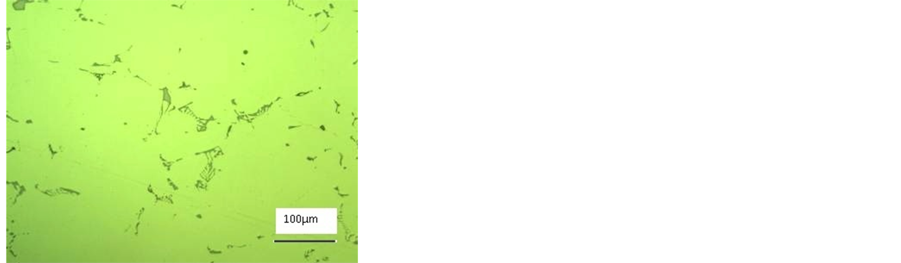
Microstructures of ingots and cold-rolled coils with different Fe contents are presented in Figure 1 and Figure 2. No significant differences in the microstructures of head and butt slices were found. The liquation zone in all ingots was below 1.5 mm. Large blocky type constituents were found at a depth of 9 - 10 mm from the rolling surface in the ingots with 0.37% and 0.47% Fe, and at 11 - 12 mm depth for the ingots with 0.53% and 0.58%

Table 1 . Fe, Si and Cu content in trial lots.
 (a)
(a)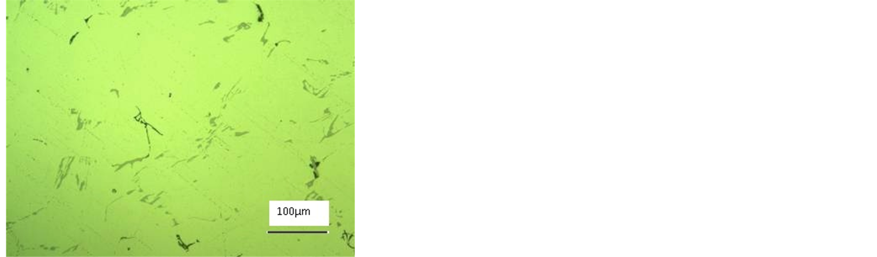 (b)
(b)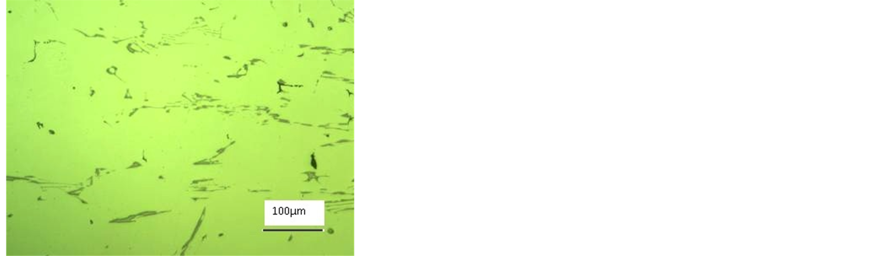 (c)
(c)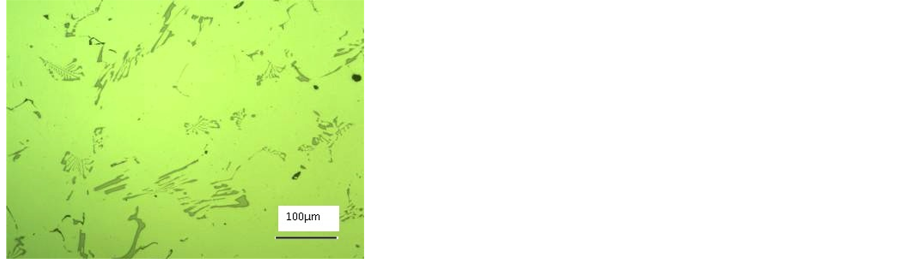 (d)
(d)
Figure 1. Microstructures at 1/4 thickness of ingots with different Fe contents: (a) 0.37%; (b) 0.47%; (c) 0.53%; (d) 0.58%.
 (a)
(a)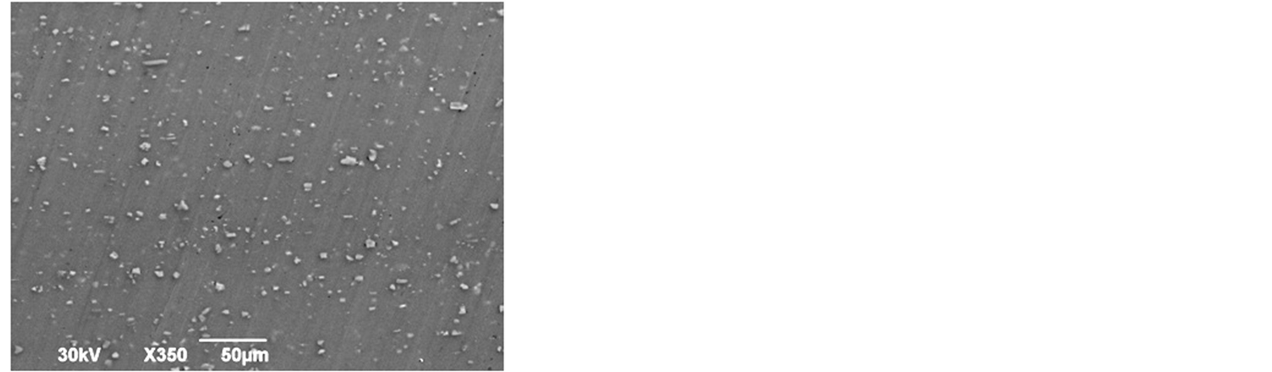 (b)
(b)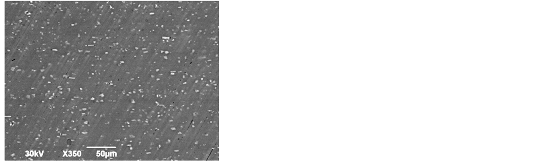 (c)
(c)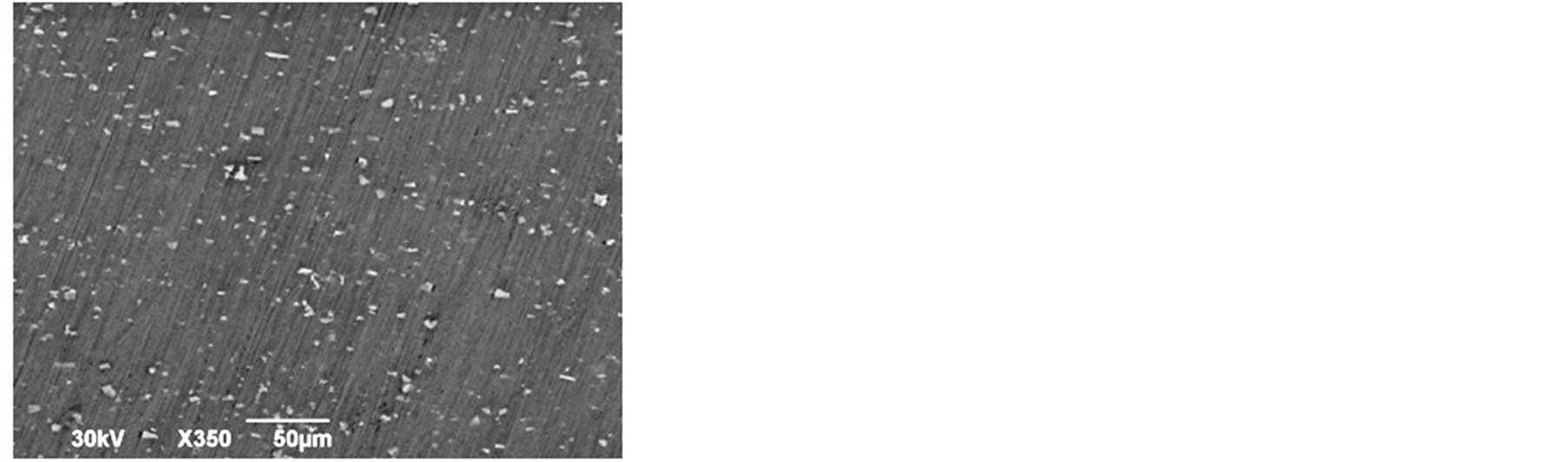 (d)
(d)
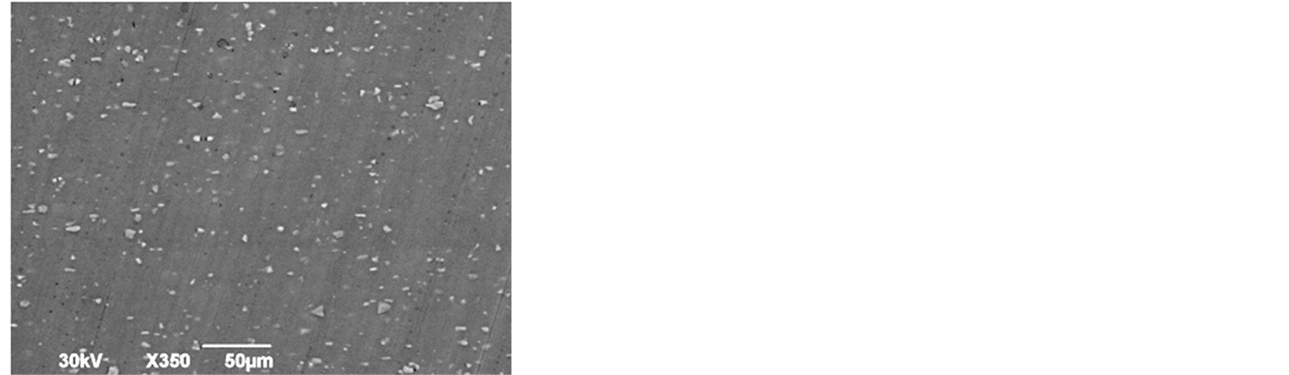
Figure 2. SEM microstructures of cold rolled coils with different Fe contents: (a) 0.37%; (b) 0.47%; (c) 0.53%; (d) 0.58%.
Fe. The Fe content had not made any effect on the maximum size of constituents 9 - 12 mm below the rolling surface. Microstructures at 1/4 ingot thickness (Figure 1) showed an increase in the volume fraction of insoluble constituents with increasing Fe content. The maximum size is noticeably smaller at 0.37% Fe-80 μm; in all other cases it is up to 150 μm.
Examination of the microstructures of the hot-rolled coils showed the same extent of recrystallization in all cases. In the cold rolled samples the volume fraction of Al6(Fe, Mn) and Al12(Fe, Mn)3Si constituents increased with increasing Fe content. As Fe content increased from 0.37% to 0.58%, the volume fraction of constituents raised from 1.67% to 2.45%. Their sizes have not noticeably changed.
Testing mechanical properties of the finished gauge coils showed that variation of Fe, Si and Cu content within the experimental ranges did not have noticeable impact on the strength characteristics (Figure 3). A certain decrease of postbake strength was noted in the sheets with 0.53% and 0.56% Fe (Figure 4). It could be caused by lower Cu content in these coils [7] . However, obtained values did not have any negative impact on buckle test results. Lower Cu content in 3104 alloy can be used for postbake strength reduction for the better formability of the alloy.
Some earing increase was noted (Figure 4) with Fe content over 0.47%. This could be connected with higher volume fraction of the insoluble constituents, which are known to surpass cube texture formation after hot mill and consequently to result in higher 45˚ earing.
Analysis of conversion results at a can plant showed that, all other conditions being equal, the number of bodymaker ironing dies changeovers per ton of processed metal reduced with increase in Fe content starting from 0.47% (Figure 5). Tear-off rate was not noticeably changed.
Tooling changeover data demonstrated that significant improvement occur at Fe content of 0.47%, i.e. when the combined volume fraction of Al6(Fe, Mn) and Al12(Fe, Mn)3Si reaches 2.03%. Further increases in Fe content only slightly reduced the number of changeovers. Thus, taking into account the undesirable consequences of
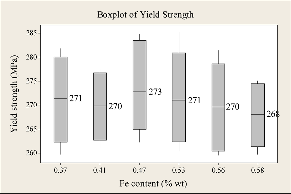
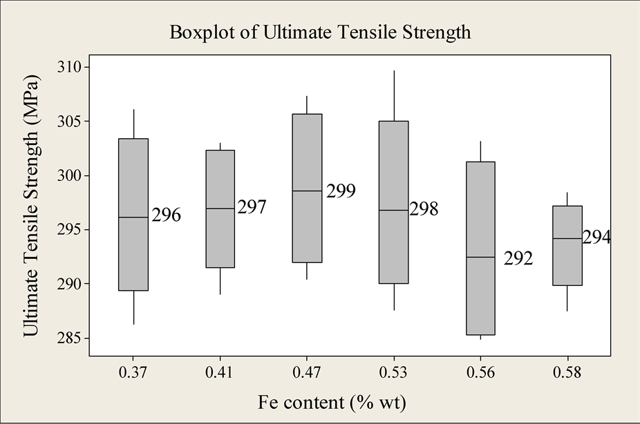
Figure 3. Ultimate tensile strength and yield strength with different Fe contents.
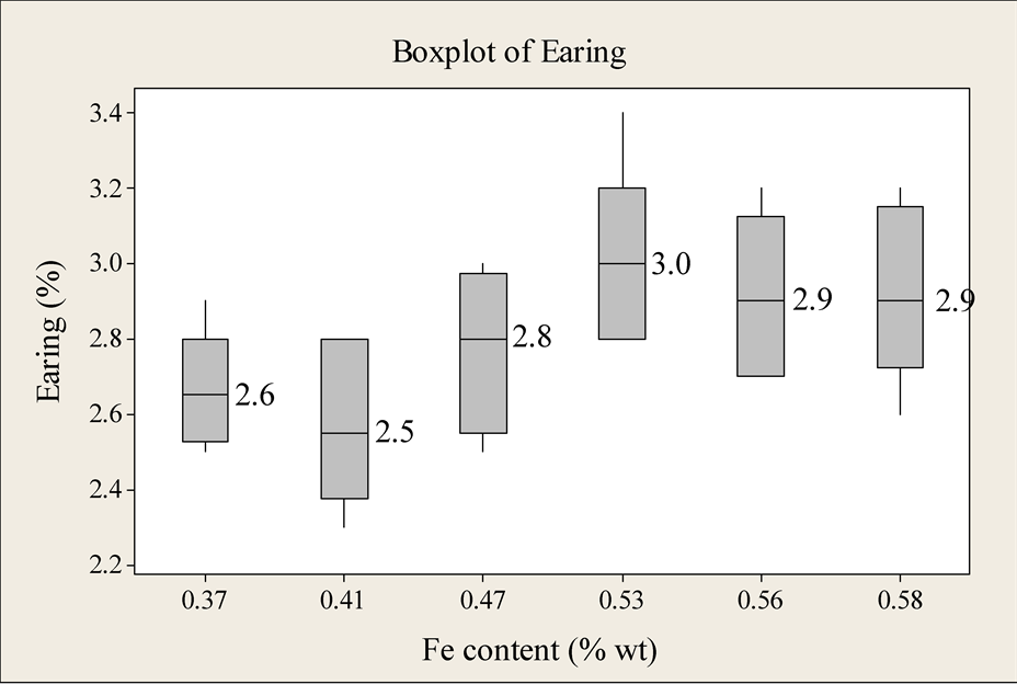
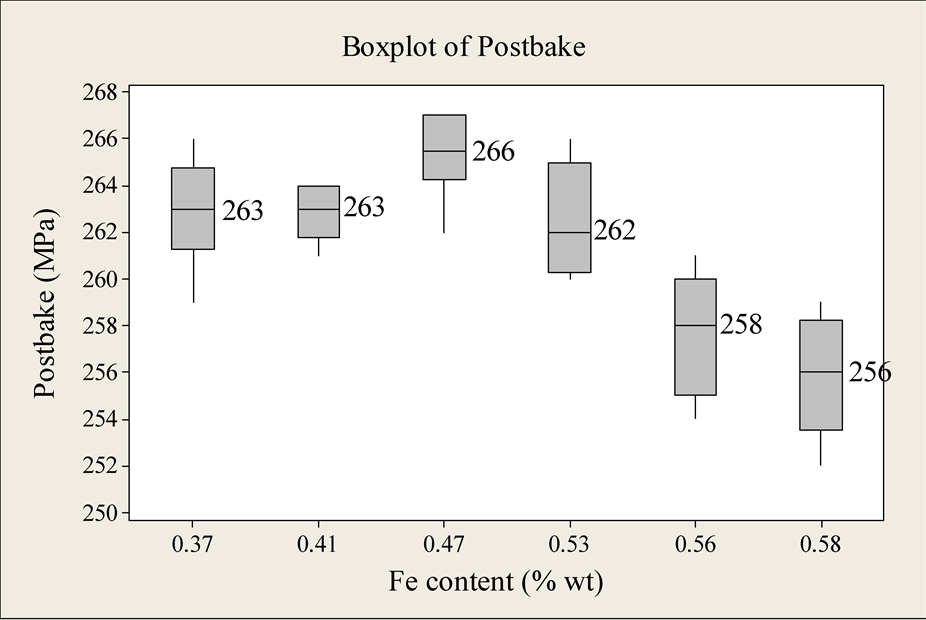
Figure 4. Postbake and earing with different Fe contents.
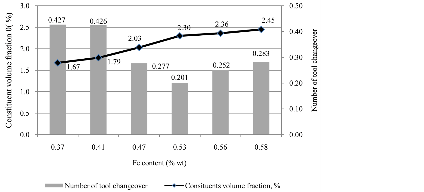
Figure 5. Volume fraction of constituents and number of tool changeovers.
further increase of Fe content such as greater earing and possible occurrence of large constituents, which may cause higher tear-off rate during can forming, the optimal Fe could be considered between 0.47% and 0.53%.
4. Conclusions
1) Increase in Fe content in 3104 alloy showed rise in volume fraction of insoluble Fe-containing constituents in the cold rolled sheet. It increased from 1.67% for 0.37% Fe to 2.45% for 0.58% Fe. The sizes of constituents did not noticeably change.
2) Significant resistance in tool galling was noted starting from 0.47% Fe. Al6(Fe, Mn) and Al12(Fe, Mn)3Si constituents abrade ironing dies, removing pick-up. Minimum number of tooling changeovers were noted at 0.53% Fe. Further increase in Fe content virtually brought no positive effects.
3) Taking into account the undesirable consequences of increase in Fe content, such as greater earing, the optimal Fe could be considered between 0.47% and 0.53%.
References
- Westerman, E.J. (1993) Silicon: A Vital Element in Aluminum Beverage Can Body Stock. In: Morris, J.G., et al., Eds., Aluminum Alloys for Packaging, TMS, 1-16.
- Liu, Q. and Lin, L. (2010) Current Status of Research and Industries of Al Sheets in China. Proceedings of the 12th International Conference on Aluminium Alloys, Yokohama, The Japan Institute of Light Metals, 20-29.
- Rouns, T.N. (1998) Composition and Preheating Effects on the Dispersoid and Insoluble Constituent Particle Evolution in 3xxx Alloys. In: Das, S.K., Ed., Aluminum Alloys for Packaging III, TMS, 3-20.
- Wang, X. and Kamat, R.G. (1996) A Technique to Measure Intermetallic Size Distribution in Aluminum Can Body Stock. In: Morris, J.G., et al., Eds., Aluminum Alloys for Packaging II, TMS, 209-222.
- Robert, D.D. and Sanders Jr., R.E. (1991) Recent and Future Development of D&I Body Stock, Science and Engineering of Light Metals. In: Hirano, K., Oikawa, H. and Ikeda, K., Eds., Sendai, 747-753.
- Points, R.A. (2001) Factors in Casting & Rolling of Can Stock. International Melt Quality Workshop, Madrid.
- Sanderson, W.B. (1998) Can Sheet Performance as a Function of UBS Quality. In: Das, S.K., Ed., Aluminum Alloys for Packaging III, TMS-AIME, Warrendale, 151-156.