Circuits and Systems
Vol. 3 No. 3 (2012) , Article ID: 20201 , 7 pages DOI:10.4236/cs.2012.33031
Study of New Planar Resonator’s Topologies Little Perceptible in Variations of Substratum’s Height
1Laboratory of Electronics and Communication (LEC), Ecole Mohammadia d’Ingénieurs (EMI), Mohammed V University—Agdal, Rabat, Morocco
2Department of Electrical Engineering, Graduate School of Technology, Moulay Ismail University, Meknes, Morocco
Email: nizar.zrigui@ensil.unilim.fr, zenkouar@emi.ac.ma, briseddik@gmail.com
Received March 6, 2012; revised April 6, 2012; accepted April 13, 2012
Keywords: Resonator; Planar Technology; Topologies; Echo’s Frequency; Substratum’s Height; Quality Factor
ABSTRACT
The mobile communication (radio, mobile, satellite telephony…) insert band filters which are required to comply with stringent pass-band characteristics concerning the selectivity, the group delay, the insertion losses and the mass and volume. The mass and volume of payload electronic equipment is a significant contributor to the overall cost of space systems. Within this framework, many improvements were made in the design of filters and multiplexers which represent a considerable portion of the overall satellite payload. The High Temperature Superconducting (HTS) planar technology permits to realize compact size filtering devices. Moreover, it could also provide a superior performance not attainable by any other technology. However, not controllable parameters in the manufacturing processes (indistinctness of the engraving, the not uniformity of substratum thickness) do not allow to obtain a precision on the echo’s frequency and to keep a high quality factor. So, it is necessary to use method to tune the center frequency of filters after the fabrication or to study new resonator topologies which present lower sensitivity to LAIO3 substrate thickness. This last point is the object of this article.
1. Introduction
At present IMUX microwaves filters of a communications satellite’s payload are realized in volume technology, they have an important weight and dimensions; they constitute an important part of the payload and consequently contribute strongly to the launch price of a satellite.
The solution at present studied to obtain a gain of mass of these filters is the use of the planar superconducting technology.
The studies showed that it was not possible to respect the templates imposed because of not controllable parameters. A regulation is then inescapable when we wish to optimize their electric performances. The most current solution is the use of reticule adjusting screws inserted into cases. This technique is mastered well this day but it increases in a significant way the losses the filter insertion of and the size of cases so limiting their mechanical integration. Of more these regulations are expensive and thus it is recommended to aim towards topology of filters less sensitive to the chances of manufacturing and\or adjustable in a single pass.
The simplification of regulation procedures could be a strong argument in favor of the new resonators topology solution in superconducting technology.
The modification of the resonators shape returns their even insensible or less sensitive frequencies of echo to the substratum thickness. Indeed to decrease the effect of the substratum thickness in the structures have try to concentrate the electromagnetic field meadows of the circuit surface between the superconductor and the substratum, what allows to obtain a precision of lower frequency in ±5 MHz with regard to the central frequency (4 GHz) while keeping a raised quality factor.
Indeed we are interested in the improvement of resonator performances in the shape of empty cross used in a communications satellite payload. We show that the shape modification of this resonator allows decreasing the frequency gap.
The resonator studied in this article has the advantage to remedy the problems of dimensions and weight of the volume structures used in the IMUX. Furthermore it is characterized by a good reproducibility, an ease of interconnection with the other active circuits under forms of MMIC (Monolithic Microwave Integrated Circuit), and a low manufacturing cost.
The superconducting technology [1] is interesting because it allows making decrease the metallic losses. Furthermore, superconducting planar filters present very high factors, which can reach 107 at 10 GHz and T = 77 K. Consequently, they could replace the volume filters used in IMUX in the satellites payloads. Indeed, the powers received by these are very low and can be supported by a planar technology.
The lanthanate of alumina (LaAlO3) of cubic structure has a perfect agreement of stitch with the YbaCuO deposit [2]. This substratum presents a dielectric constant of 23, 6 and a losses tangent of 7, 6 × 10⁻⁶ to a frequency of 10 GHz and a temperature of 77 K [3].
The various simulations were realized under ADS Momentum, tool of electromagnetic simulation 2.5 D adapted to the simulation of planar structures.
2. Technologies of Filters
2.1. The Volume Filters
It is filters which allow to support strong powers and to have a very high quality factor a narrow bandwidth, and a high selectivity… they are the reasons for which they are at present used in communications satellites in spite of the inconveniences which they present at the level of the dimensions and of the weight.
The volume filters are realized from generally cylindrical, rectangular status-enhancing metallic cavities, or are built from guides of waves.
2.2. Planar Filters
Planar filters are used to remedy the problems of dimensions and weight of the volume structures. Furthermore they are characterized by a good reproducibility, an ease of interconnection with the other circuits, and a low cost of manufacturing. On the other hand, they cannot support strong powers and their factor of vacuous quality is low in classic technology (microstrip, coplanar, and leak out with localized elements). Planar filters can use superconductive materials to decrease the metallic losses seen that these materials present a surface’s resistance very low RS when they are cooled below their critical temperature.
2.3. Microwaves Filters Used in the Payload of a Communications Satellite
In the payload of a communications satellite, there are four types of filters: the filters of reception, the filters of IMUX, the filters of OMUX and the filters of broadcast (Figure 1).
2.4. The Multiplexer of Entrance
Has to insure the separation of the band of reception in
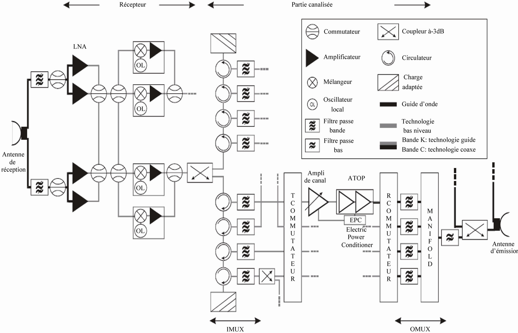
Figure 1. Plan typical block of a reception-broadcast chain of payload of fixed service satellite [4].
several channels. These filters will thus have to have a very low band and be very selective to maximize the number of channels on the useful band.
Furthermore, the undulation in the band has to remain very low to avoid a modulation live as a parasite of the amplitude [5-7]. An IMUX contains so many filters as channels. The increase of the transmission capacity is translated by an increase of the number of channels and thus the number of IMUX filter. This evolution leads naturally to an increase of the weight and the volume of the demultiplexing functions which constitute a not insignificant part of the payload (10% of the mass of the repeater), see of the global satellites load (Tables 1 and 2). Where from the interest to realize studies to win on the mass of filters constituting the IMUX.
A possible solution to mitigate these inconveniences is to replace the volume filters by planar filters. However, the use of classic plating leads to too much raised losses of insertion. On the other hand, these losses can be minimized by using superconductive materials.
The first experimental results showed the appearance of a frequency gap with regard to the fixed template. It was shown that variation is bound to the fact, that the thickness of the substratum used during the manufacturing is not perfectly identical to that fixed in the simulations during the conception [8]. To mitigate this problem, new structures of resonators were studied.
3. Results
3.1. Experiment—1
The structure of resonator in empty cross (Figure 2) will constitute the reference of our study.
Simulations in Momentum of this topology have allowed us to have an idea on the influence of thickness variation of the substratum on the frequency of echo and the value of the factor quality Q0. The purpose of the study is to optimize this topology to decrease the effect of these variations.
To calculate the quality factor in load QL we made a simulation in the band of analysis 40,044 GHz - 40,059 GHz. Figure 3 illustrates the results found for a density of meshing of 120 cells by wavelength (cells/wavelength).
The LaAlO3 substratum of thickness 500 µm possesses a relative permittivity εr of 23, 6 and a losses tangent equal to 1 × 10⁻⁵ in 77 K and 4 GHz [9,10].
The precise properties of the superconductive materials will be introduced through an impedance of surface
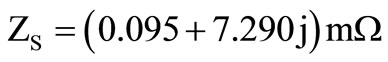 .
.
The determination of the quality factor is made in two stages. A first simulation allows determining the quality factor in load QL then the second calculation without losses allows determining the outside quality factor Qe.
3.1.1. Calculation with Losses: Determination of the Quality Factor in Load
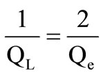
The quality factor in load QL characterizes at the same time the intrinsic losses of the resonator and coupling systems:
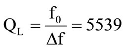
or: 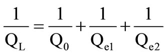
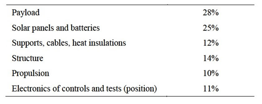
Table 1. Analysis of a typical communications satellite mass.
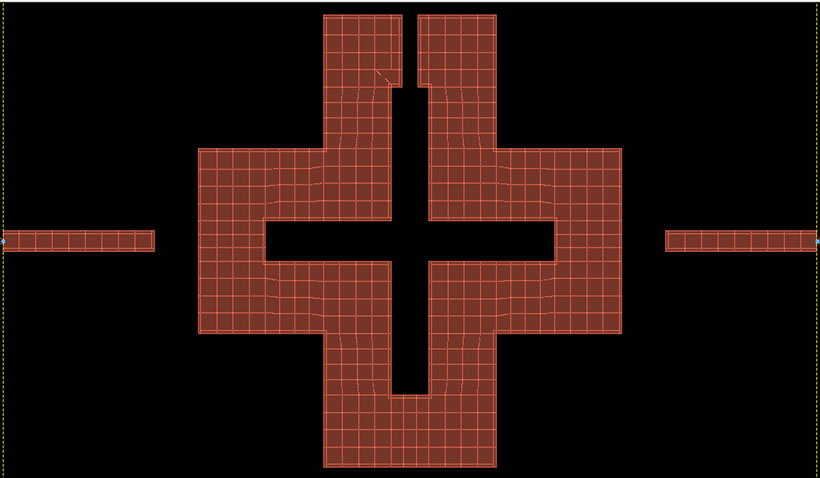
Figure 2. Resonator in cross studied.
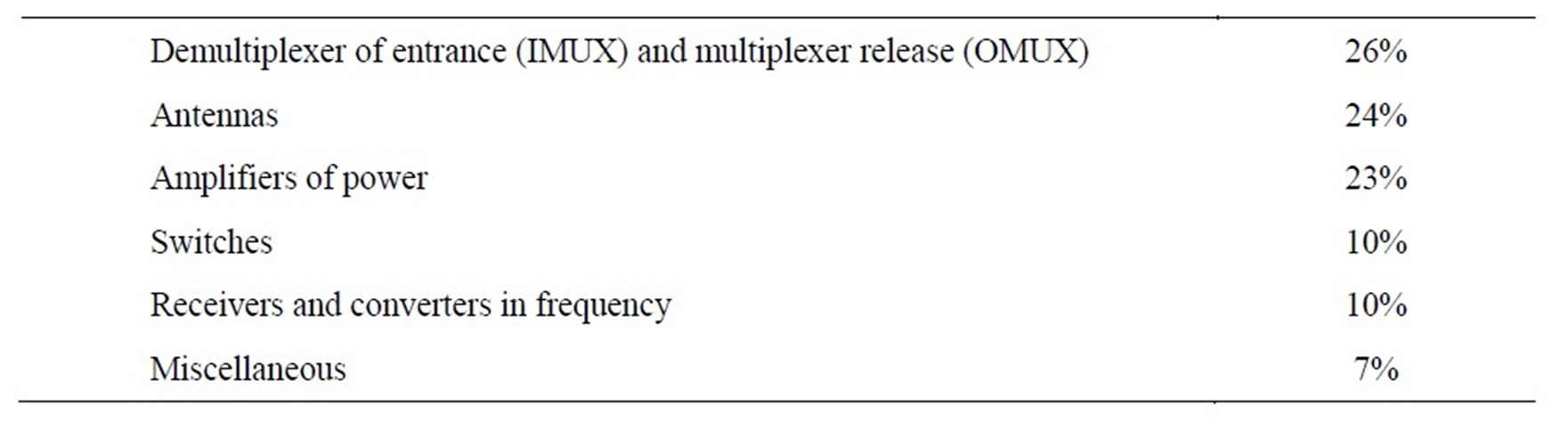
Table 2. Analysis of a typical payload mass of communications satellite.
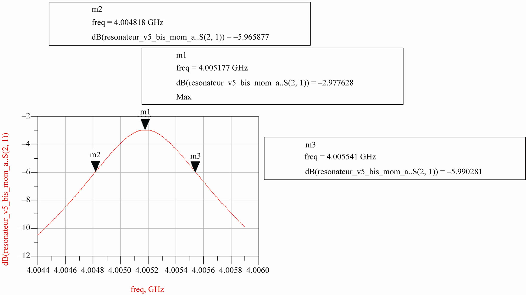
Figure 3. S21 module visualization of the resonator studied according to the frequency.
Q0 characterizes the intrinsic losses of the resonator and Qe1 and Qe2 characterizes systems coupling.
The system is symmetric (gaps between the lines of excitement and the resonator are identical) thus Qe1 = Qe2 = Qe.
3.1.2. Calculation without Losses (Q0 Aims towards the Infinity): Determination of Qe
All the drivers (2GND + strip) are perfect drivers and losses tangent of the substratum is equal in zero
![]()
![]() QL =
QL = = 7866
The knowledge of QL and Qe allows calculating the quality factor Q0
Thus: 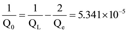
![]()
![]() Q0 = 18723
Q0 = 18723
This quality factor is thus very high and very sensitive to the errors of measure.
The substratum on which microwaves resonators are engraved can present slightly different thicknesses (Figure 4).
Furthermore, when substratums of average thicknesses 500 µm with the lowest tolerances are commanded it is possible that the reserved substratum have an average thickness of 495 µm ± 1 µm. It is for that reason that we
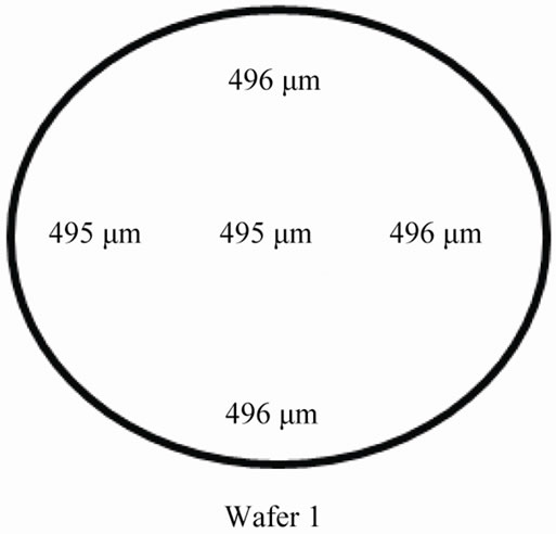
Figure 4. Thicknesses of the commanded substratum.
made simulations on various thicknesses to see the effect of the variation of the substratum thickness on the frequency of echo. The following Table 3 illustrates the found results.
3.2. Experiment—2
To concentrate the electromagnetic field in the surface of the structure, we began by adding a vertical bar in the middle of the opened cross Figure 5. We varying the bar dimensions of ±1 µm or look by simulations under ADS for the bar size which approaches most in the value of the echo’s frequency while keeping the high quality factor.
By modifying the length and the width of this bar we realized that it was possible to decrease the frequency gap due to the variations of the substratum thickness.
The bar is optimized for a length L = on 2450 µm and a width W = 325 µm and spaced out by 25 µm with regard to the cross.
The obtained results are the following ones (Table 4).
We notice that with this topology the obtained gap is 1.09 × 10⁻³ MHz for a variation of 2 µm of substratum height (between 495 and 497 µm). In the case of the topology in initial cross (of reference), the gap was 2.4 × 10⁻³ MHz. We thus obtain a 50% decrease.
3.3. Experiment—3
In a second part we were interested in the influence of a horizontal bar superconducting placed inside the resonator (Figure 6).
We looked for the minimum of variations by modifying the value of the length and the width. We end in the following results for a length L = 2450 µm and a width
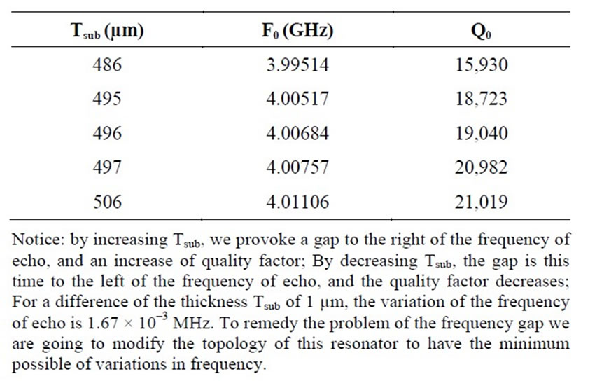
Table 3. Variations of F0 and Q0 for a resonator in cross.
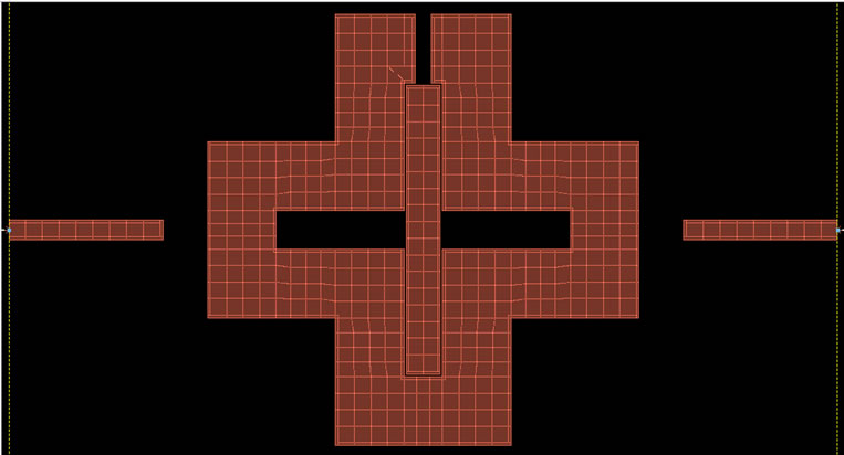
Figure 5. Topology No. 1.
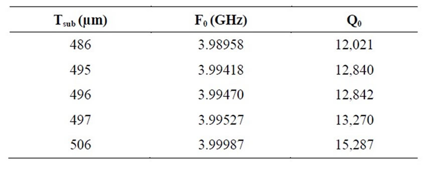
Table 4. Variations of F0 and Q0 for the topology No. 1.
W = 285 µm and spaced out of 20 µm with regard to the cross.
The obtained results are presented in the Table 5.
With this topology we were able to have a gap of 7.4 × 10⁻⁴ MHz for a variation of 2 µm (between 495 and 497 µm). In the case of the topology in initial cross, we had a gap of 2.4 × 10⁻³ MHz. We thus obtain a 69% decrease.
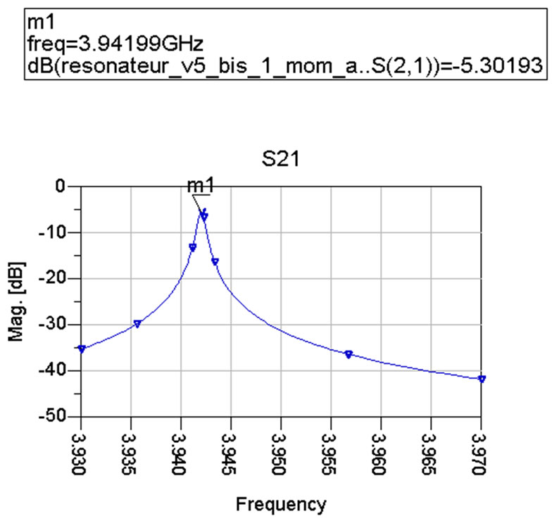
For this topology we obtain the module of presented S21 represent Figure 7.
3.4. Experiment—4
After vertical bar optimization to have the minimum of possible frequency gap, we added a horizontal bar as showed on Figure 8.
The bar is optimized for a length L = on 2405 µm and a width W = 290 µm and spaced out by 40 µm with regard to both quoted by the cross.
For this topology we obtain the module of presented S21 represent Figure 9.
The obtained results are presented in Table 6.
We notice that with this topology we were able to have a gap of 6.5 × 10⁻⁴ MHz for a variation of 2 µm (between 495 and 497 µm). This represents a 73% decrease with regard to the initial topology.
The introduction of coplanar structures allows decreasing the variation of the frequency of echo according to the height of the substratum but degrades the quality

Figure 6. Topology No. 2.
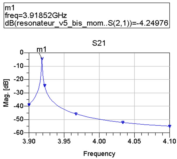
Figure 7. Module of S21 according to the frequency for the topology No. 2.
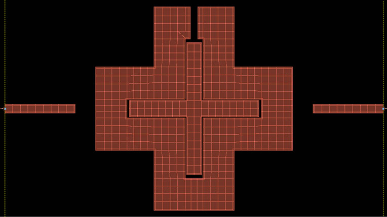
Figure 8. Topology No. 3.
Notice: the bar dimensions are obtained after several simulations of S21 relative to lengths and heights variations of ±1 µm. One always looks for the dimensions which present not enough frequency gap with regard to the echo frequency 4 GHz.
Figure 9. S21 module visualization of according to the frequency of the resonator No. 3.
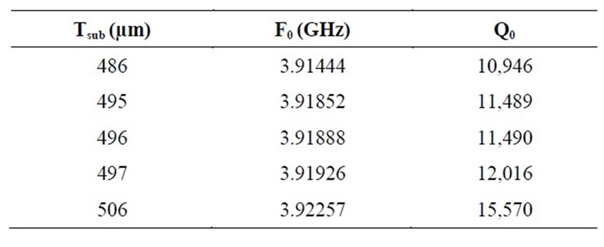
Table 5. Variations of F0 and Q0 for the topology No. 2.
factor [11].
This various topologies also has the advantage to decrease the dimensions of the resonator because to obtain a frequency of echo of 4 GHz, it would be necessary to decrease the structure dimensions.
Table 7 shows that the final topology (full cross) has allowed to decrease the frequency gap of 73% with regard to the initial structure (empty cross) this topology then present the advantage to be insensible in the sub-
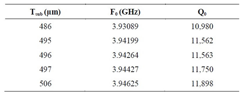
Table 6. Variations of F0 and Q0 for the topology No. 3.
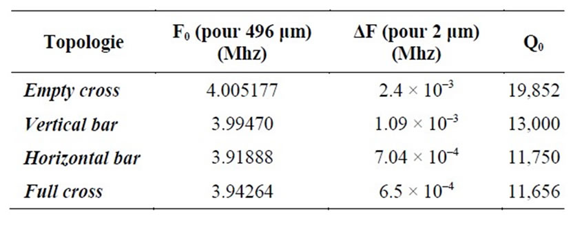
Table 7. Comparison of the topology.
stratum height variations.
4. Conclusions
The topology in cross presents the advantage to be little sensitive to the variations of substratum height.
It thus allows freeing himself from regulations systems which increase the dimensions and the weight of filters. The purpose of this article was the improvement of the superconductive planar resonator performances in cross dedicated to the realization of microwaves filters used in the payload of communications satellites, to look for possibility of obtaining a minimum of the echo frequency gap without degrading the quality factor.
The study carried out on this topology consisted in making simulations with the aim of seeing the effect of the addition of a vertical bar, then a horizontal bar inside the initial structure. These modifications allow concentrating the electromagnetic field meadows of the surface of the circuit between the superconductor and the substratum. Our final structure (full cross) has allowed to decrease the effect of the substratum thickness on the echo frequency everything one keeping a high value of quality.
The addition of vertical bar and\or a horizontal bar allows adjusting the frequency gap caused by the manufacturing errors by moving the echo frequency to the left or to the right. This technique allows freeing itself from cumbersome regulation systems.
5. Acknowledgements
This work was realized in the electronics and communications laboratory of the Mohammadia School of engineers in cooperation with Meknes Graduate School of Technology.
REFERENCES
- G. Huot, “Cofabrication Monolithique de Capteurs à Supraconducteur YBa2Cu3O7δ et d’une Electronique Supraconductrice sur Même Substrat de Silicium,” Ph.D. Thesis, Caen University, Caen, 2004.
- Wikipedia. http://fr.wikipedia.org/wiki/Oxyde_mixte_de_baryum_de_cuivre_et_d’yttrium
- E. Picard, “Filtres Planaires en Technologies Innovantes Pour des Applications Multimédia,” Ph.D. Thesis, Limoges University, Limoges, 2004.
- S. Moraud, “Etude et Conception de Nouvelles Technologies de Filtres Destinés à être Intégrés aux Différents Niveaux de la Charge Utile d’un Satellite de Télécommunications,” Ph.D. Thesis, Limoges University, Limoges, 1998.
- S. B. Cohn, “Microwave Band Pass Filters Containing High Q Dielectric Resonators,” IEEE Transactions on Microwave Theory and Techniques, Vol. 16, No. 4, 1968, pp. 218-227. doi:10.1109/TMTT.1968.1126654
- S. J. Fiedziusko, “Dual Mode Dielectrics Resonator Loaded Cavity Filters,” IEEE Transactions on Microwave Theory and Techniques, Vol. 30, No. 9, 1982, pp. 1311-1316. doi:10.1109/TMTT.1982.1131253
- D. Baillargeat, “Analyse Globale de Dispositifs Microondes par la Méthode des Eléments Finis. Application aux Filtres à Résonateurs Diélectriques,” Ph.D. Thesis, Limoges University, Limoges, 1995.
- S. Courreges, “Les Matériaux Ferroélectriques et Supraconducteurs Appliqués à la Conception de Dispositifs Microondes,” Ph.D. Thesis, Limoges University, Limoges, 2007.
- K. Lascaux, “Analyse, Conception et Réalisation de Dispositifs Microondes Planaires Supraconducteurs en Bande Ka: Applications aux Systèmes de Communication par Satellites,” Ph.D. Thesis, Limoges University, Limoges, 2002.
- M. V. Jacob, J. Mazierska, N. Savvides, S. Ohshima and S. Oikawa, “Comparison of Microwave Properties of YBCO Films on MgO and LaAlO3 Substrates,” Physica C: Superconductivity, Vol. 372-376, 2002, pp. 474-477. doi:10.1016/S0921-4534(02)00725-6
- H. R. Yi, S. K. Remillard and A. Abdelmonem, “A Novel Ultra-Compact Resonator for Superconducting Thin-Film Filters,” IEEE Transaction on Microwave Theory and Techniques, Vol. 51, No. 12, 2003, pp. 2290-2296.