Journal of Modern Physics
Vol.4 No.12(2013), Article ID:40628,9 pages DOI:10.4236/jmp.2013.412194
Key Role of Hybridization between Actinide 5f and Oxygen 2p Orbitals for Electronic Structure of Actinide Dioxides
1Department of Physics, Tokyo Metropolitan University, Tokyo, Japan
2Faculty of Science, University of the Ryukyus, Okinawa, Japan
3Advanced Science Research Center, Japan Atomic Energy Agency, Ibaraki, Japan
Email: hotta@tmu.ac.jp
Copyright © 2013 Yu Hasegawa et al. This is an open access article distributed under the Creative Commons Attribution License, which permits unrestricted use, distribution, and reproduction in any medium, provided the original work is properly cited.
Received October 2, 2013; revised November 6, 2013; accepted November 27, 2013
Keywords: Tight-Binding Approximation; Actinide Dioxides; f-p Hybridization; Crystalline Electric Field Potential
ABSTRACT
In order to promote our understanding on electronic structure of actinide dioxides, we construct a tight-binding model composed of actinide 5f and oxygen 2p electrons, which is called f-p model. After the diagonalization of the f-p model, we compare the eigen-energies in the first Brillouin zone with the results of relativistic band-structure calculations. Here we emphasize a key role of f-p hybridization in order to understand the electronic structure of actinide dioxides. In particular, it is found that the position of energy levels of Г7 and Г8 states determined from crystalline electric field (CEF) potentials depends on the f-p hybridization. We investiagte the values of the Slater-Koster integrals for f-p hybridization, (fpσ) and (fpπ), which reproduce simultaneously the local CEF states and the band-structure calculation results. Then, we find that the absolute value of (fpπ) should be small in comparison with (fpσ) = 1 eV. The small value of |(fpπ)| is consistent with the condition to obtain the octupole ordering in the previous analysis of the f-p model.
1. Introduction
Actinide dioxides form a group of important materials from technological viewpoints of a nuclear reactor fuel and a heterogeneous catalyst. On the other hand, this material group has also been actively investigated from a viewpoint of basic science because of its high symmetry of the fluorite structure of the space group Fm3m [1-3]. In the circumstance of such high symmetry of crystal structure, it is possible to observe peculiar ordering of multipole higher than dipole, when we change the kind of actinide ions. Among several magnetic properties of actinide dioxides, a mysterious low-temperature ordered phase of NpO2 has attracted continuous attention in the research field of condensed matter physics.
The phase transition in NpO2 has been confirmed in 1953 from the observation of a peak in the specific heat around 25 K [4]. Due to the behavior of magnetic susceptibility [5,6], it has been first considered that the antiferromagnetic order occurs. Unfortunately, no dipole moments have been observed in the low-temperature phase and a puzzling situation has continued. Neutron scattering experiments have revealed that the ground state of the crystalline electric field (CEF) potential is Г8 [7], which carries multipole moments. Then, from several phenomenological works on the ordered phase, a key role of octupole degree of freedom has been focused [8-12]. In fact, the octupole ordering has been strongly suggested by 17O-NMR experiment [13] and also by inelastic neutron scattering study [14]. As for the microscopic origin of such higher-order multipole ordering, it has been shown that octupole order is stabilized by the orbitaldependent superexchange interaction, and obtained by the second-order perturbation of 5f electron hopping in the Г8 degenerate Hubbard model on a fcc lattice [15-17]. Recently, significant contribution of dotriacontapole moment has been also pointed out [18,19].
Since the multipole moments originate from 5f electrons, it seems to be natural to consider the Hubbard-like model of 5f electrons. However, from the crystal structure of actinide dioxides, it is also important to include explicitly 2p electrons, since actinide ion is surrounded by eight oxygens and the main hopping process between nearest neighbor sites should occur from the f-p hybridization. In this sense, f-p model is more realistic Hamiltonian for actinide dioxides. In fact, the f-p model for actinide dioxides has been analyzed in the fourth-order perturbation theory in terms of f-p hybridization [20]. Then, it has been revealed that octupole order actually occurs even when we include oxygen 2p electrons. However, there has been a peculiar point that the octupole phase appears only for the small absolute value of (fpπ)/(fpσ) [20], where (fpσ) and (fpπ) are Slater-Koster integrals between f and p orbitals. The reason of the sensitivity of the octupole ordered phase concerning the f-p hybridization has not been understood yet.
In order to clarify the role of f-p hybridization for the appearance of octupole ordering, Maehira and Hotta have performed the band-structure calculations for actinide dioxides by a relativistic linear augmented-plane-wave method with the exchange-correlation potential in a local density approximation [21]. It has been found that the energy bands in the vicinity of the Fermi level are mainly due to the hybridization between actinide 5f and oxygen 2p electrons. It has been also pointed out that the electronic structure at the Г point in the first Brillouin zone is not consistent with that of the local CEF state. One reason for this inconsistency is that the CEF potentials are not satisfactorily included in the calculations, but it is difficult to control the magnitudes of CEF potential and f-p hybridization in the band-structure calculations. It is highly requested to reveal the role of f-p hybridization for the simultaneous explanation of the octupole ordering and the local CEF states.
In this paper, in order to clarify the roles of hybridization between actinide 5f and oxygen 2p electrons for the electronic structure of actinide dioxides, we analyze the tight-binding f-p model in detail. Except for the Slater-Koster integrals of (fpπ) and (fpσ), we determine the parameters in the model from the comparison with experimental results and band-structure calculations. In order to reproduce the result of the relativistic bandstructure calculations and obtain the electronic structure consistent with the local CEF state, we find that the Slater-Koster parameters for f-p hybridization should be limited in a certain range. A typical result is found for (fpπ)  0 and (fpσ)
  1 eV, which is consistent with the condition for the appearance of the octupole ordering.
The organization of this paper is as follows. In Section 2, in order to make this paper self-contained, we briefly review the relativistic band-structure calculations for actinide dioxides. It is meaningful to define the problems included in the band-structure calculations. In Section 3, we explain a way to construct the f-p model in the tightbinding approximation. Then, we determine the parameters of the model, except for (fpσ) and (fpπ), from the comparison with the experimental and band-structure calculation results. In Section 4, we depict the energy band structure of the f-p model by changing the values of f-p hybridization. We deduce the reasonable regions for (fpσ) and (fpπ). In Section 5, we discuss some future problems concerning the electronic structure of actinide dioxides. Finally, we summarize this paper. Throughout this paper, we use such units as = kB = 1.
2. Brief Review of Band-Structure Calculation for Actinide Dioxides
Let us briefly review the band-structure calculation results in order to clarify the problem in the understanding of electronic structure of actinide dioxides. As for details, readers should consult Ref. [21].
We have performed the calculations by using the relativistic linear augmented-plane-wave (RLAPW) method. We assume that all 5f electrons are itinerant and perform the calculations in the paramagnetic phase. Note that we should take into account relativity even in the calculations for solid state physics because of large atomic numbers of the constituent atoms. The spatial shape of the one-electron potential is determined in the muffin-tin approximation. We use the exchange and correlation potential in a local density approximation (LDA). The self-consistent calculation is carried out for the experimental lattice constant for actinide dioxides.
In Figure 1, we show a typical result for NpO2 along the symmetry axes in the Brillouin zone. In the energy band structure in the vicinity of the Fermi level EF, there always occurs a hybridization between actinide 5f and oxygen 2p states for actinide dioxides. The lowest six bands originate from the oxygen 2p states and are fully occupied and the width of oxygen 2p band is about 4.76
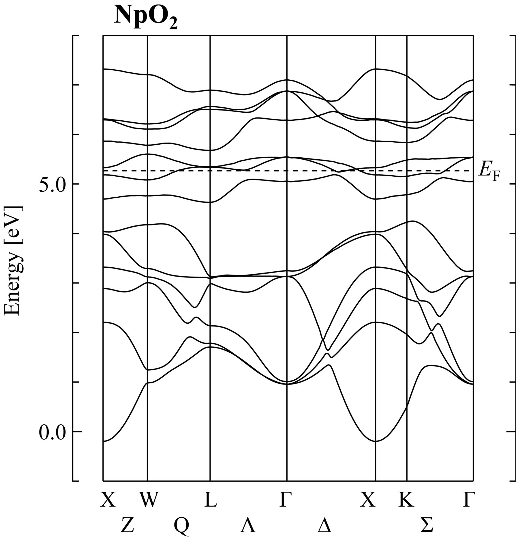
Figure 1. Energy band structure of NpO2 obtained by the self-consistent RLAPW method. Note that we pick up only 5f and 2p bands around EF, which indicates the position of the Fermi level.
eV. Narrow bands lying in the region 4.5 - 7.5 eV are the 5f bands which are split into two subbands by the spinorbit interaction. The spin-orbit splitting in the 5f states is estimated as 0.95 eV, which is consistent with that for isolated neutral Np atom. Note that in the LDA calculation, we find the metallic state for NpO2, not the insulating state. This point will be discussed later.
Here we remark that Г7 doublet and Г8 quartet levels appear around EF at the Г point. It should be noted that the Г7 level is lower than the Г8 in our band-structure calculations. However, from the CEF analysis on the basis of the j-j coupling scheme, Г8 becomes lower than Г7 in actinide dioxides. When we accommodate 5f electrons in Г8 orbitals, we obtain Г5 triplet for n = 2, Г8 quartet for n = 3, and Г1 singlet for n = 4, as experimentally found in the CEF ground states of UO2 [22], NpO2 [7], and PuO2 [23,24]. Note here that n denotes the number of local 5f electrons.
In order to resolve the problems, it is necessary to improve the method to include the effect of CEF potentials beyond the simple estimation of the Madelung potential energy. However, it is a difficult task to perform such improvement concerning the formulation of the bandstructure calculation. Thus, in this paper, we choose an alternative method to exploit the tight-binding f-p model for the purpose to understand the role of f-p hybridization for the change of CEF states in the tight-binding model. By changing the parameters in the f-p model, we attempt to clarify the key quantities which characterize the electronic structure of actinide dioxides.
3. Tight-Binding Approximation
3.1. Crystal Structure and Unit Cell
Before proceeding to the construction of a tight-binding model for actinide dioxides with the fluorite structure, first let us define the unit cell including one actinide ion and two oxygen ions, as shown in the Figure 2. The basis vectors of the fcc lattice are given by a1 = (a/2, a/2, 0), a2 = (0, a/2, a/2), and a3 = (a/2, 0, a/2), where a is the lattice constant. Thus, in Figure 2, positions of adjacent four actinide ions are given by i, i + a1, i + a2, and i + a3, where i denotes the position vector for one actinide ion.
The positions of eight nearest-neighbor oxygen ions are given by b1 = (a/4, a/4, a/4), b2 = (−a/4, a/4, a/4), b3 = (a/4, −a/4, a/4), b4 = (−a/4, −a/4, a/4), b5 = (−a/4, −a/4, −a/4), b6 = (−a/4, a/4, −a/4), b7 = (a/4, −a/4, −a/4), and b8 = (a/4, a/4, −a/4). Note that the two oxygens, O1 and O2, in the same unit cell are specified by b1 for O1 and b5 for O2, respectively.
3.2. CEF State
Now we define the basis of f electrons when we consider the electronic model for actinide dioxides with the fluo-
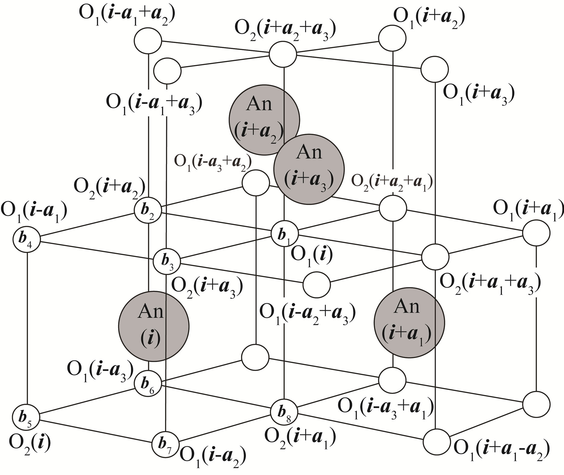
Figure 2. Crystal structure of AnO2. Large solid circles denote actinide ions of which positions are given by i, i + a1, i + a2, and i + a3. Small open circles indicate oxygen ions. Note that two oxygen ions, O1(i) and O2(i), are included in the unit cell containing one actinide ion specified by i.
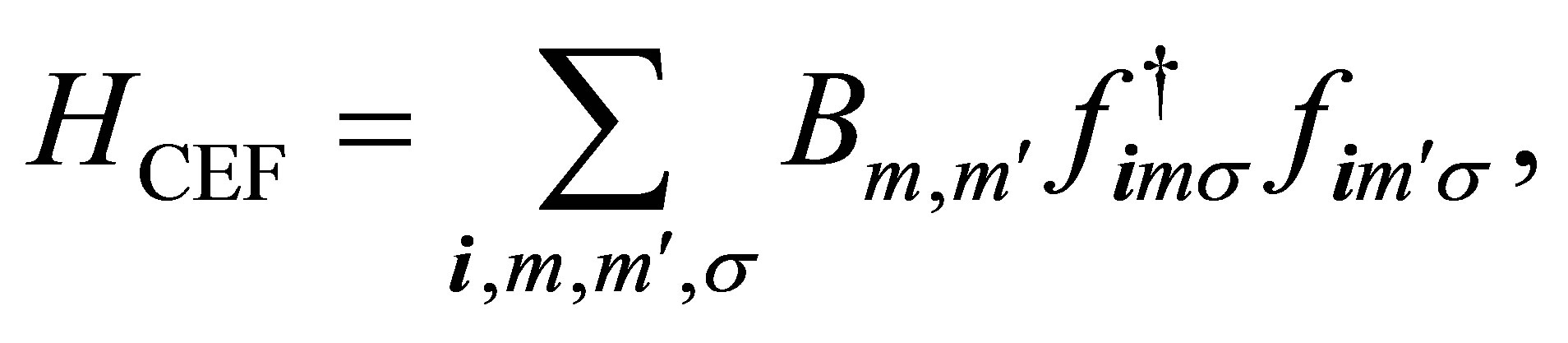
rite structure. For the purpose, we solve the problem of one f electron in the CEF potential. The CEF Hamiltonian is written as
 (1)
(1)
where fimσ is the annihilation operator of f electron at site i with spin σ in the orbital specified by m. Note that m is the z-component of angular momentum l = 3. Note also that the spin-orbit coupling is not included at this stage.
Since the fluorite structure belongs to Oh point group, Bm,m’ is given by using a couple of CEF parameters  and
and  for angular momentum l = 3 as [25,26]
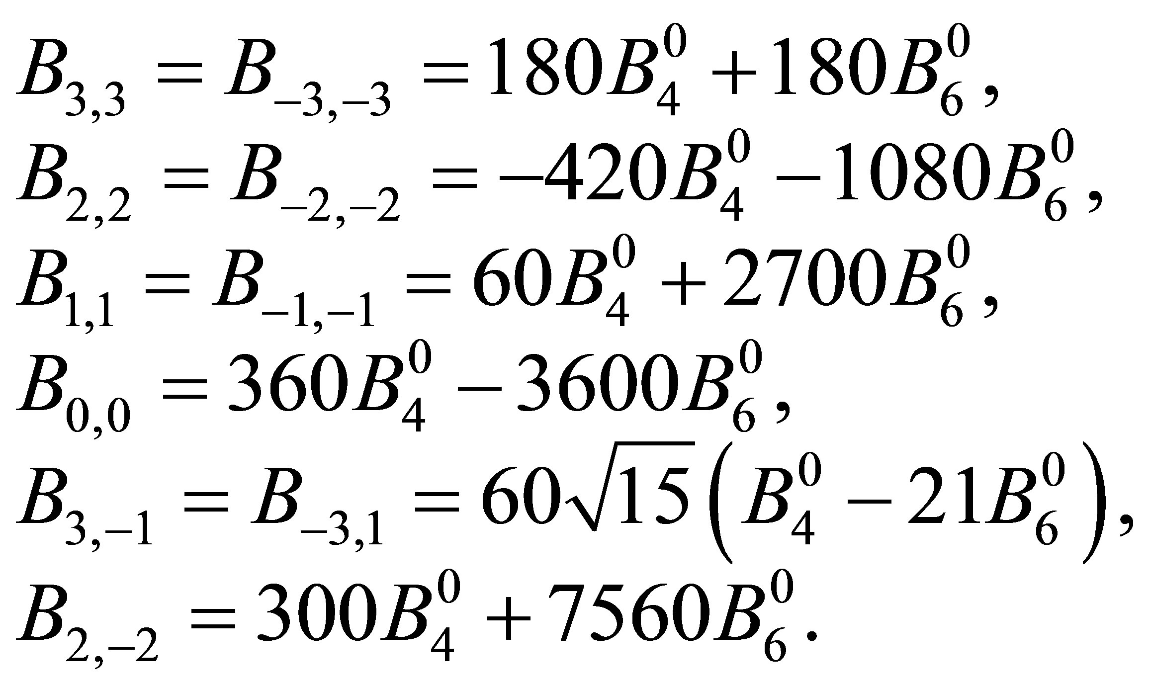 (2)
(2)
Note the relation of Bm,m' = Bm',m.
After performing the diagonalization of HCEF, we obtain three kinds of CEF states: Г2 singlet [xyz], Г4 triplet [x(5x2−3r2), y(5y2−3r2), z(5z2−3r2)], and Г5 triplet [x(y2−z2), y(z2−x2), z(x2−y2)]. The corresponding CEF energies are given by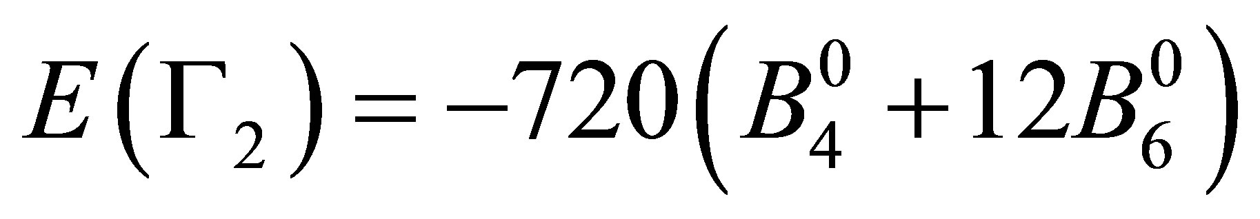 ,
,
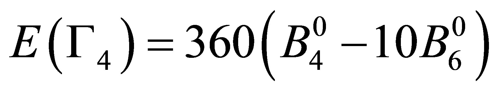 , and
, and
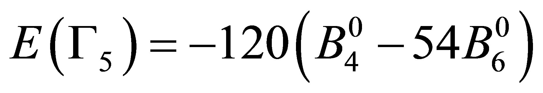 . Note that these seven states are elements of cubic harmonics for l = 3. In the traditional notation, we express CEF parameters
  and
and  as
as 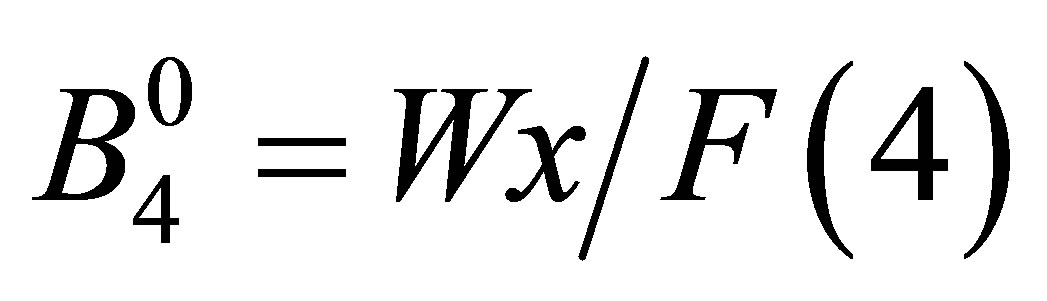 and
and 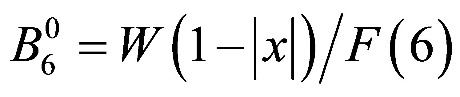 with F(4) = 15 and F(6) = 180 for angular momentum l = 3 [26]. Note that x specifies the CEF scheme for Oh point group, while W determines an energy scale for the CEF potential. Then, we obtain
 (3)
(3)
The values of W and x will be discussed later.
Since we will construct the model in the cubic system, it seems to be natural to use these cubic harmonics as f-electron basis function. Thus, in the following, we define μ as the index to distinguish the orbitals of cubic harmonics. Note that μ takes 1 - 7 and the definitions are as follows: 1: xyz, 2: x(5x2 − 3r2), 3: y(5y2 − 3r2), 4: z(5z2 − 3r2), 5: x(y2 − z2), 6: y(z2 − x2), and 7: z(x2 − y2). The corresponding energy Eμ is given by the above equations.
3.3. Hamiltonian
The Hamiltonian is given by
 (4)
(4)
where Hf and Hp denote fand p-electron part, respectively, while Hfp indicates f-p hybridization term. In the following, we explain the construction of each term in detail.
The f-electron part is given by
 (5)
(5)
where fkμσ is the annihilation operator of f electron with spin σ in the orbital μ,  is the f-electron dispersion due to the hopping between nearest neighbor actinide ions, Ef is the f-electron level, Eμ denotes the CEF potential energy of μ orbital, λ is the spin-orbit interaction, and ζ is the spin-orbit matrix element.
Concerning the expression of the spin-orbit coupling, it is necessary to step back to the basis of the spherical harmonics. On the basis labelled by m, the spin-orbit interaction ζm,σ,m',σ' is expressed as
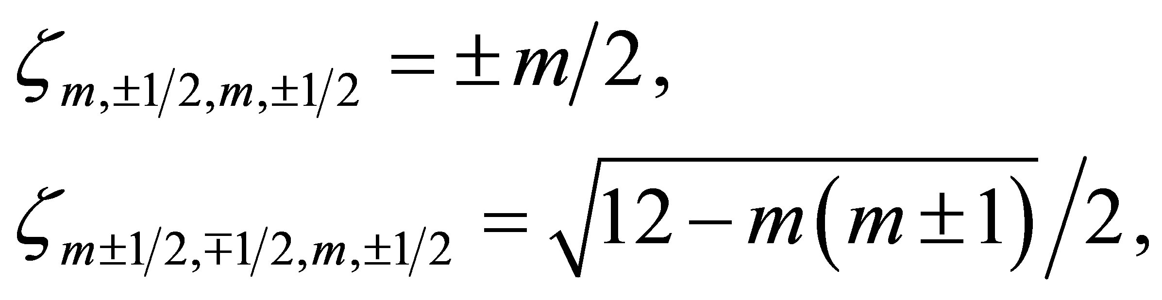 (6)
(6)
and zero for the other cases. By transforming the basis from m to μ, we obtain ζμ,σ,μ',σ' in Equation (5).
The f-electron dispersion in Equation (5) is expressed as
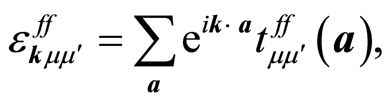 (7)
(7)
where a denotes the vectors connecting twelve nearest neighbor sites of the fcc lattice and  indicates the f-electron hopping amplitude between μ and μ’ orbitals along the direction of a. Here we note that a runs among
 ,
,  ,
,  ,
,  ,
,  , and
, and  The hopping integral
  is expressed by using the Slater-Koster table [27,28]. Here we consider only the f-electron hopping through σ bond (ffσ).
The f-p hybridization term is written as
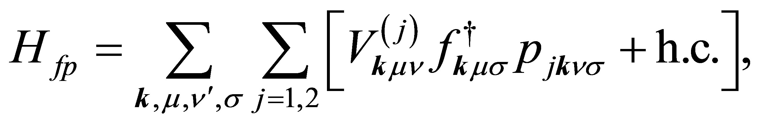 (8)
(8)
where pjkνσ is the annihilation operator of p electron with spin σ in the orbital ν of j-th oxygen and j denotes the label of oxygen ions in the unit cell, as shown in Figure 2. Note that n runs among x, y, and z which correspond to px, py, and pz orbitals, respectively. The hybridizations V(1) and V(2) are, respectively, written as
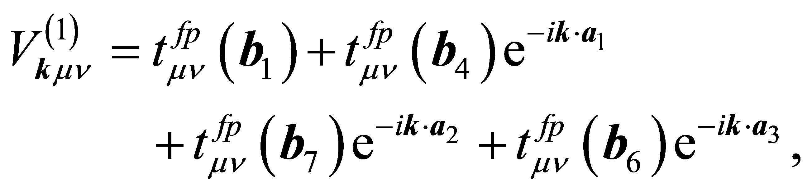 (9)
(9)
and
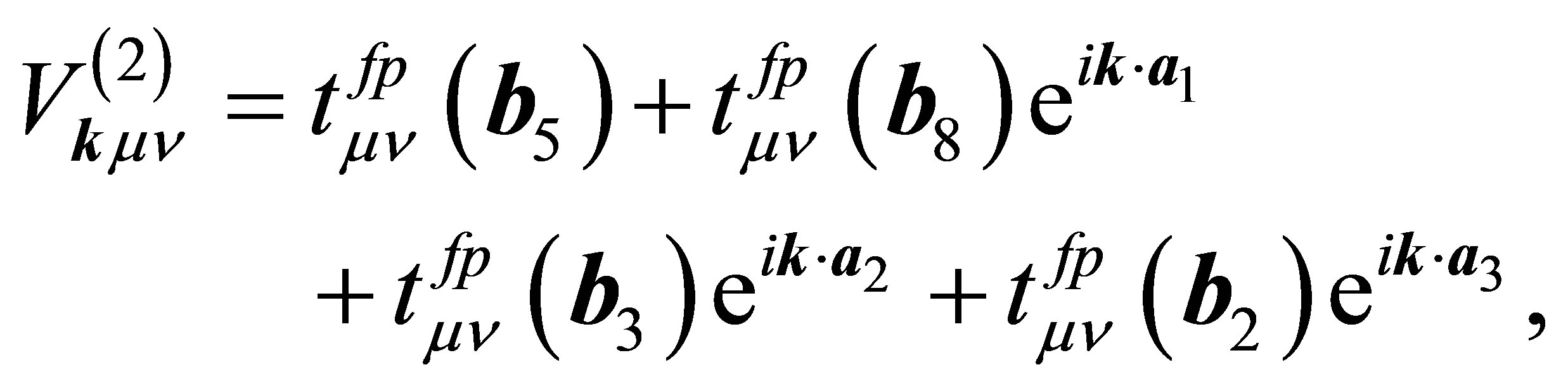 (10)
(10)
where  denotes the hopping amplitude between f and p orbitals along b direction. Here we note that b runs among b1 - b8. The hopping integral
  is represented in terms of (fpσ) and (fpπ) by using the Slater-Koster table [27,28].
The p-electron part is expressed as
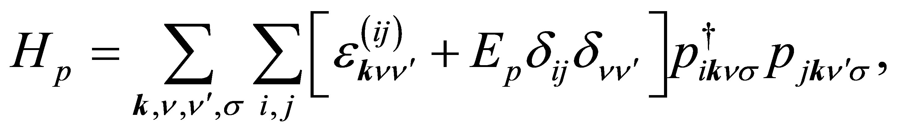 (11)
(11)
where  is the p-electron dispersion, i and j denote the label of oxygen ions in the unit cell, as shown in Figure 2, and Ep is the p-electron level. Note that we take into account nearest neighbor and next nearest neighbor hoppings for p electrons. We also note that the relations of
  and
and 
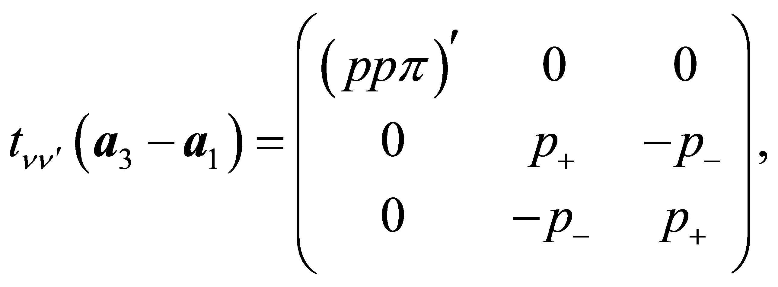
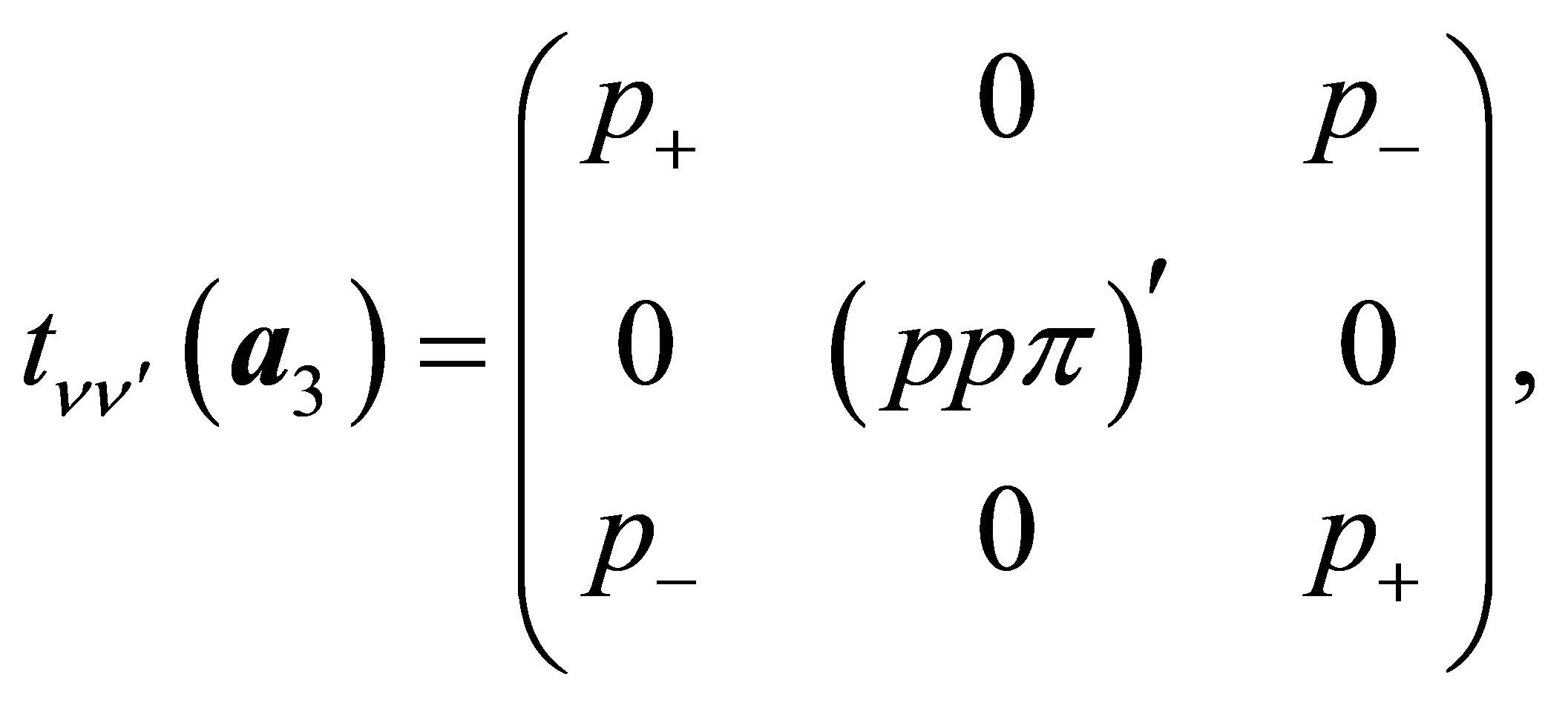
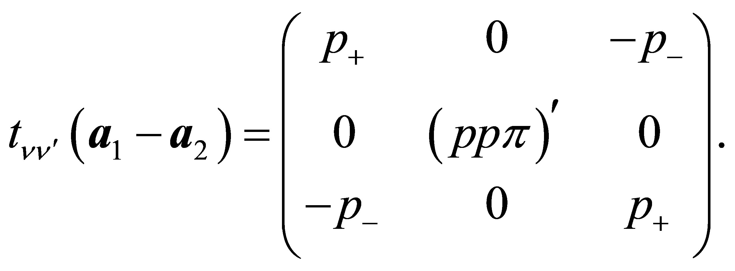
The diagonal part is given by
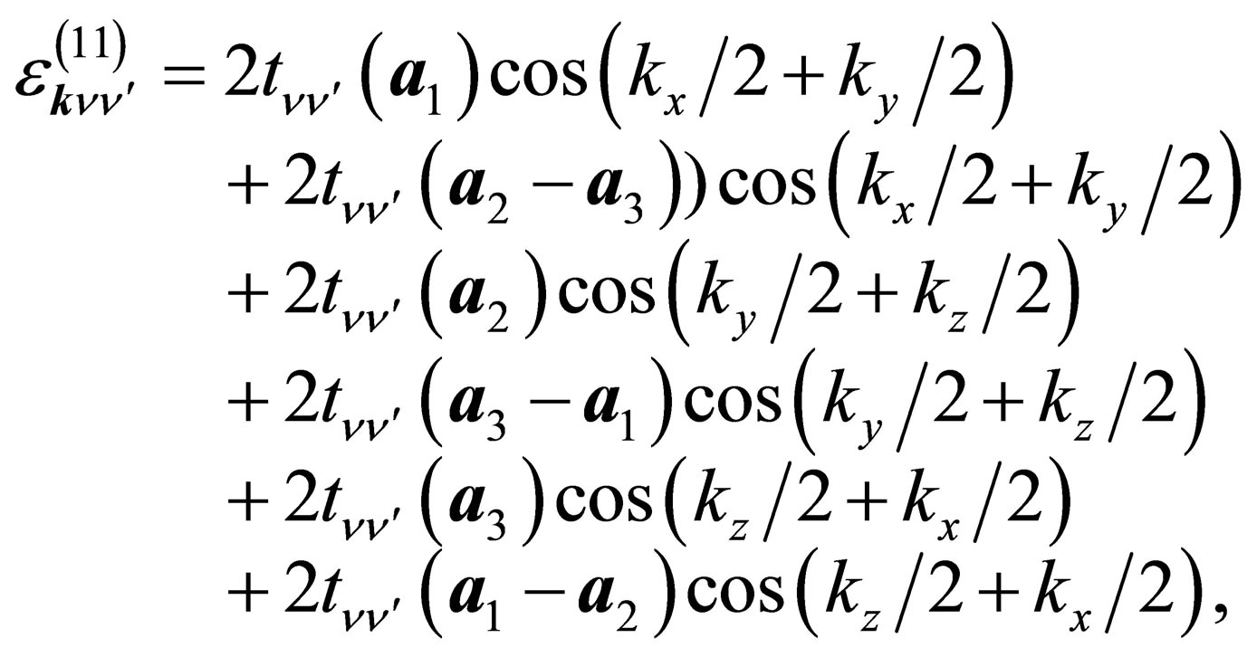 (12)
(12)
where the hopping amplitudes are given by
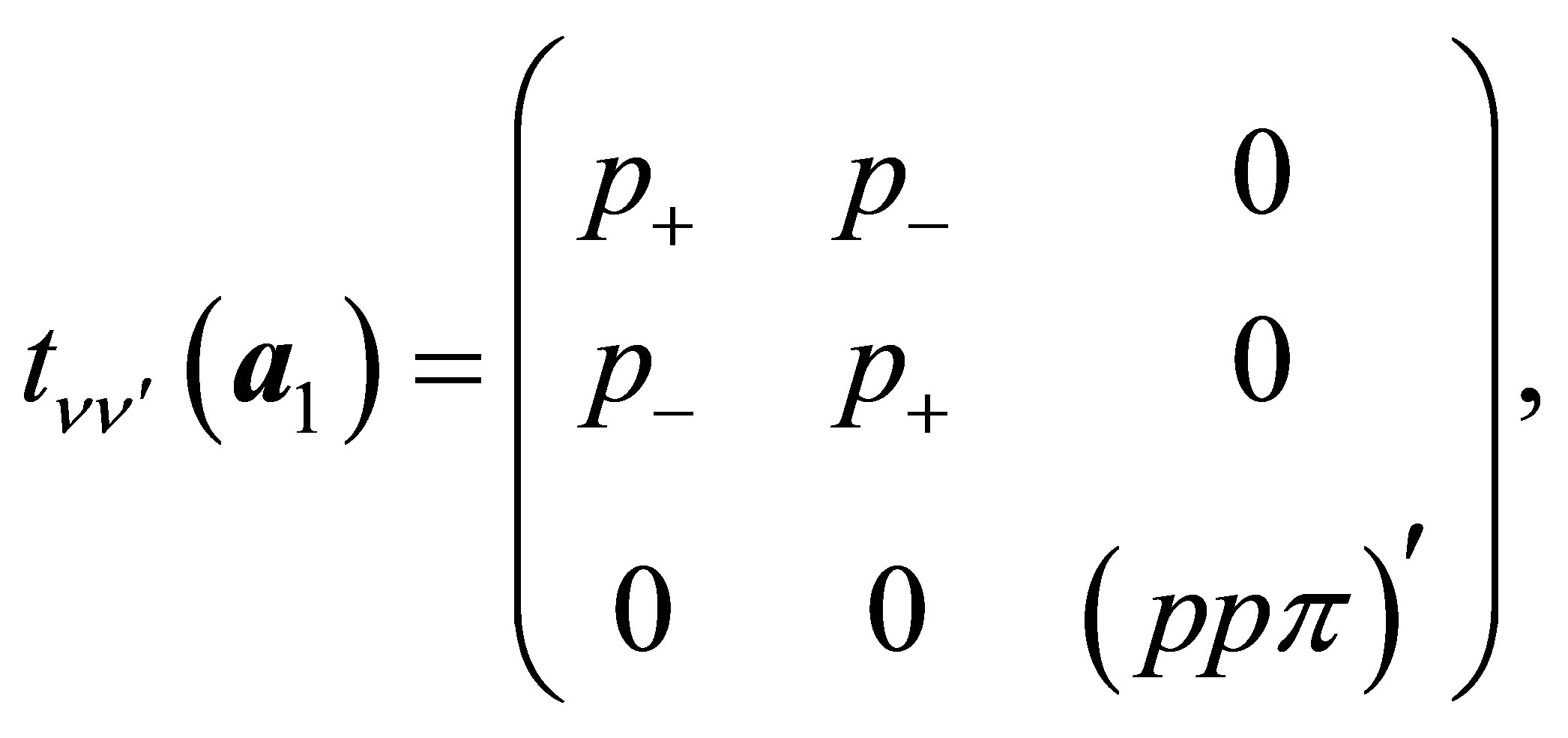 (13a)
(13a)
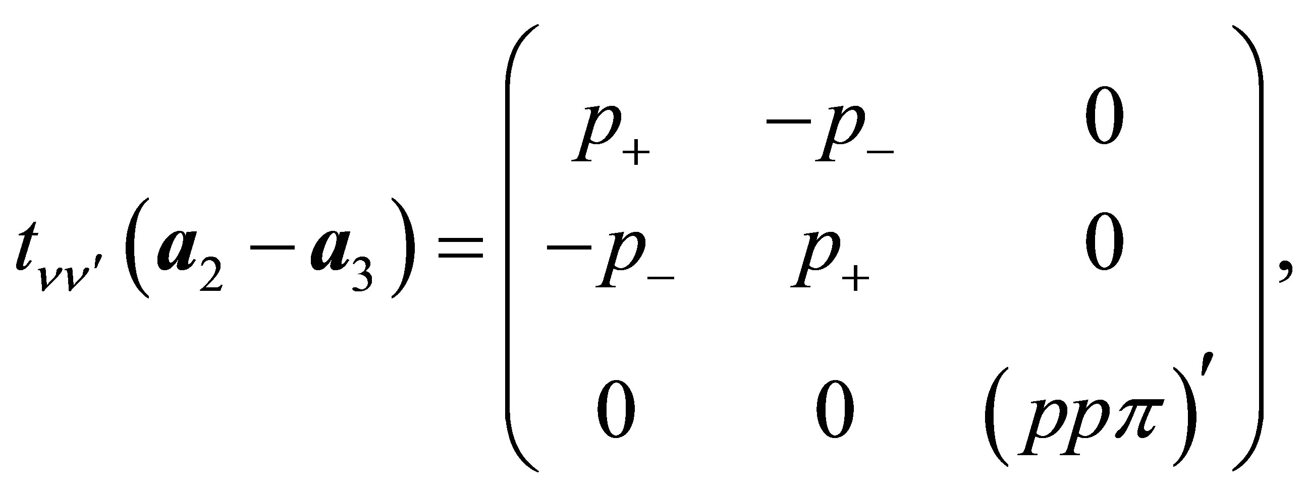 (13b)
(13b)
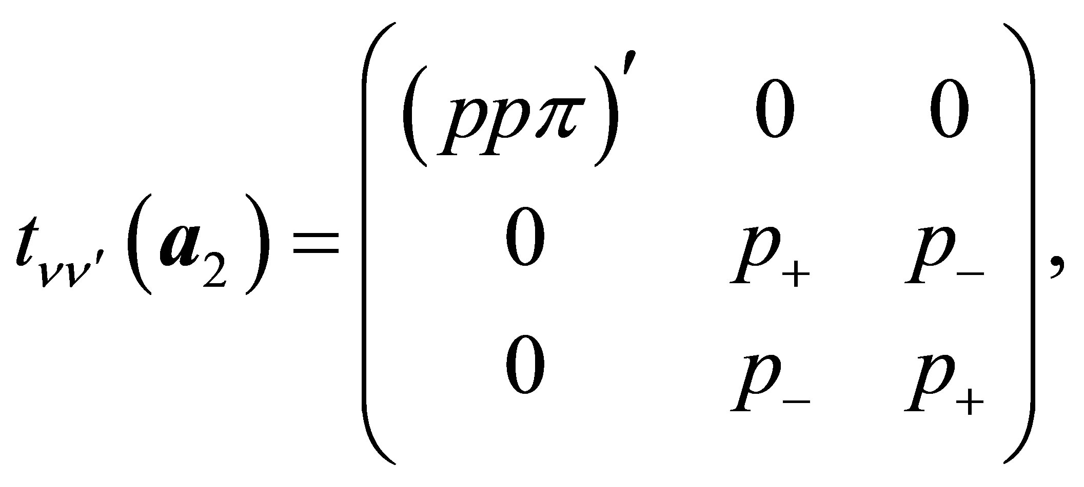 (13c)
(13c)
 (13d)
(13d)
 (13e)
(13e)
 (13f)
(13f)
Here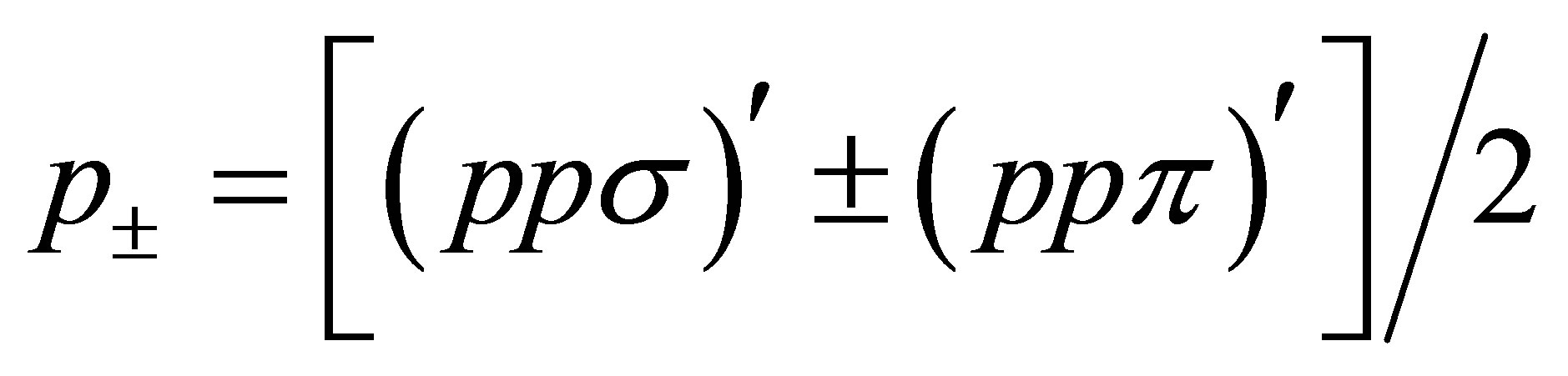 , where (ppσ)' and
(ppπ)' denote the Slater-Koster integrals of p electron between next-nearest neighbor oxygen sites.
As for the off-diagonal parts, we obtain
 (14)
(14)
 (15)
(15)
 (16)
(16)
Other off-diagonal components are all zeros.
3.4. Parameters of the Model
The tight-binding Hamiltonian includes many parameters. Here we try to fix some of them from the experimental and band-structure calculations results.
CEF parameters. It should be noted that it is possible to reproduce the CEF states of actinide dioxides, when we accommodate plural numbers of f electrons in the level scheme in which Г8 is lower than Г7. As already mentioned in Section 2, we obtain Г5 triplet for n = 2, Г8 quartet for n = 3, and Г1 singlet for n = 4, as experimentally found in the CEF ground states of UO2 [22], NpO2 [7], and PuO2 [23,24]. Thus, in the present tight-binding model, we set W = −0.01 eV and x = 0.7 in order to reproduce that Г8 quartet is the ground state and Г7 is the excited state with the excitation energy of about 0.2 eV.
Spin-orbit coupling. From the relativistic band-structure calculation for actinide atom, the splitting energy between j = 5/2 and j = 7/2 states has been found to be about 1 eV. Since the splitting energy is given as 7λ/2 with the use of spin-orbit coupling λ, we fix it as λ = 0.3 eV.
fand p-electron levels. In this paper, the f-electron level Ef is set as the origin of energy, leading to Ef = 0. On the other hand, the p-electron level Ep is considered to be Ep = −4 eV from the comparison of the relativistic band-structure calculation results [21].
Slater-Koster integrals. In the model, we use seven Slater-Koster integrals as (ffσ), (fpσ), (fpπ), (ppσ), (ppπ), (ppσ)', and (ppπ)'. Among these values, concerning the p-electron hoppings, we introduce the ratio between nearest and next nearest neighbor hopping amplitudesgiven by . From the ratio of the distances of nearest and next nearest neighbor sites, we set
  [29]. As for
(ppσ) and (ppπ), we determine them as (ppσ) = 0.4 eV and (ppπ) = −0.4 eV, after several trials to reproduce the structure of the wide p bands in the relativistic band structure calculations.
Concerning (ffσ), we note that it is related with the bandwidth Wf of f electrons in the j = 5/2 states on the fcc lattice. In the limit of infinite λ, we have obtained Wf as  [30]. Note that for the case of finite λ, the width of j = 5/2 bands is deviated from Wf, but when λ is large enough as in actual actinide compounds, the bandwidth is found to be almost equal to Wf. From the comparison with the relativistic band-structure calculation results, the width of j = 5/2 bands is 0.5 - 0.7 eV, suggesting that (ffσ) is in the order of 0.1 eV. Then, we set (ffσ) = 0.1 eV in this model.
In the following calculations, due to the diagonallization of the Hamiltonian, we depict the tight-binding bands by changing (fpσ) and (fpπ), which are believed to be key parameters to understand the electronic structure of actinide dioxides.
4. Results
Now we show our results of the diagonalization of the tight-binding model. Note that in the following figures of the band structure, “0” in the vertical axis indicates the origin of the energy, not the Fermi level EF. If it is necessary to draw the line of EF, we set it from the condition of  for tetravalent Np ion in NpO2, where
  denotes the average number of f electrons per actinide ion. In the present paper, we do not take care of the difference in actinide ions.
First we consider the case in which the f-p hybridization is simply suppressed. In Figure 3(a), we show the tight-binding bands for (fpσ) = (fpπ) = 0 along the lines in the first Brillouin zone. We obtain the f and p bands which are not hybridized with each other and f bands split into j = 5/2 and j = 7/2. Note that Г8 becomes lower than Г7 at the Г point due to the effect of local CEF potentials. We observe some degeneracy in p bands which will be lifted by f-p hybridization.
In our first impression, in spite of the simple suppression of the f-p hybridization, the overall structure of f and p bands seems to be similar to that of the relativistic band-structure calculations in Figure 1. However, some significant difference is found in the p-band structure.
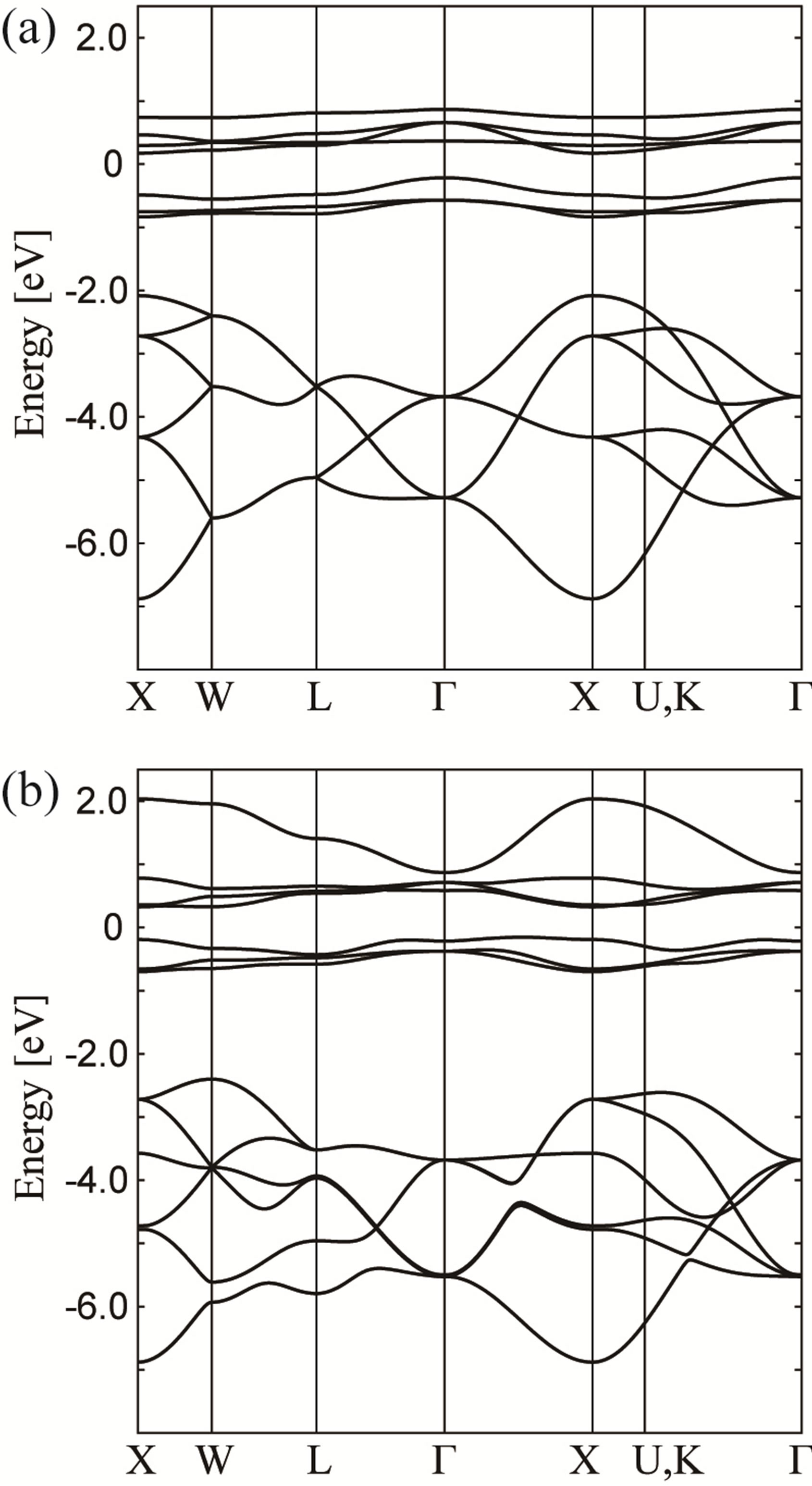
Figure 3. Energy band structure obtained by the tightbinding model for (a) (fpσ) = (fpπ) = 0 and (b) (fpσ) = 1.0 eV and (fpπ) = 0.1 eV.
For instance, we find the level crossing in the p-band structure of Figure 3(a) between the L and Г points, but we do not observe such behavior in Figure 1. Such difference originates from the simplification to consider only actinide 5f and oxygen 2p electrons. The difference in the p-band structure is not further discussed in this paper.
Next we include the f-p hybridization as (fpσ) = 1 eV and (fpπ) = 0.1 eV in Figure 3(b). Due to the effect of f-p hybridization, we find additional dispersion in f and p bands. In particular, the p-band structure becomes similar to that in the relativistic band-structure calculations. In this case, we still observe that Г8 is lower than Г7 at the Г point.
Let us now consider the cases of negative (fpπ) by keeping the value of (fpσ) = 1 eV. In Figures 4(a) and (b), we show the results for (fpπ) = −0.1 eV and −0.6 eV, respectively. For (fpπ) = −0.1 eV, we do not find significant difference in the band structure from the case of (fpπ) = 0.1 eV. However, for (fpπ) = −0.6 eV, we find that Г7
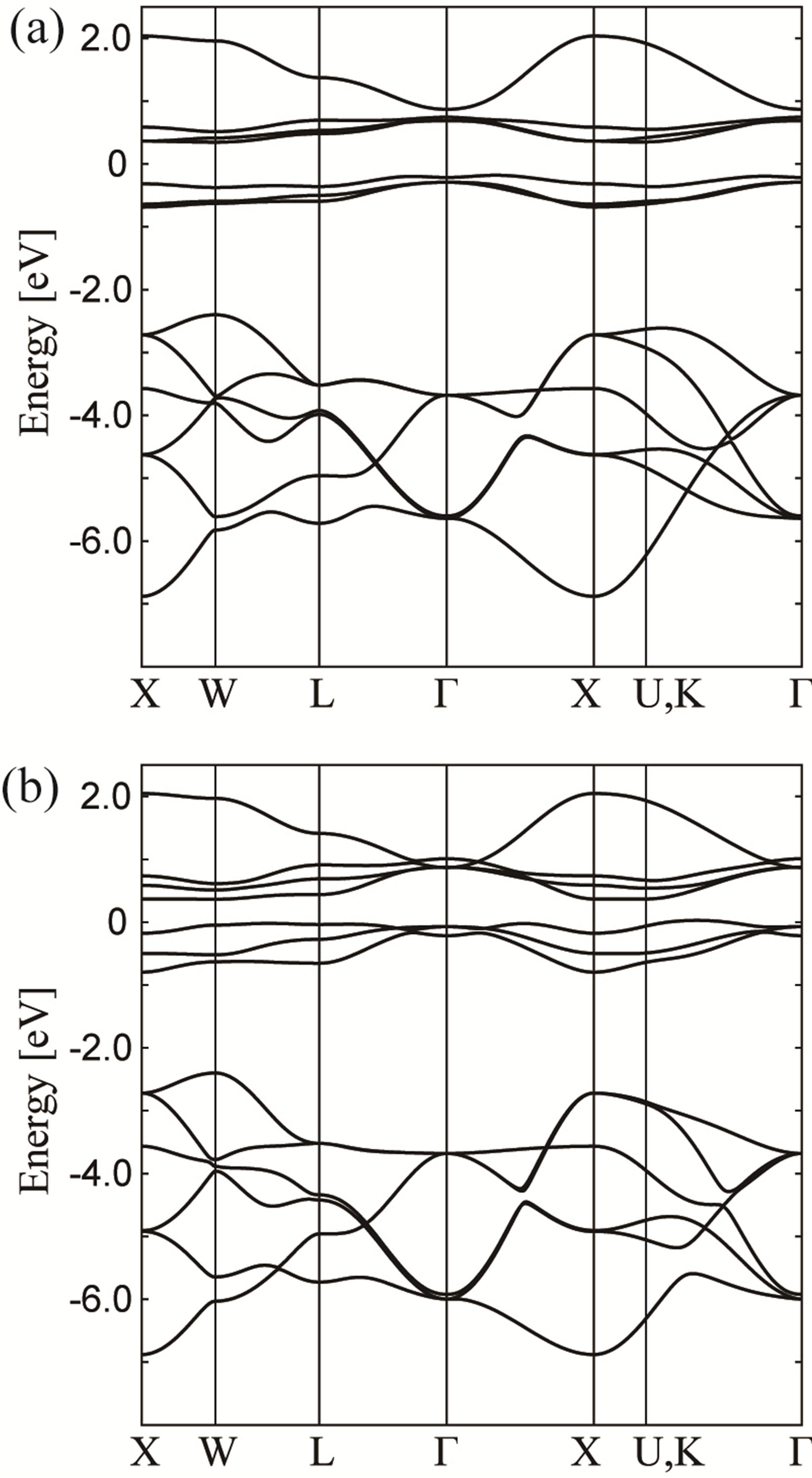
Figure 4. Energy band structure obtained by the tightbinding model for (a) (fpσ) = 1.0 eV and (fpπ) = −0.1 eV and (b) (fpσ) = 1.0 eV and (fpπ) = −0.6 eV.
is lower than Г8 at the Г point. Regarding the CEF states at the Г point, the f-p model with (fpπ) = 1 eV and (fpπ) = −0.6 eV seems to reproduce the relativistic band-structure calculation results. Note that in the p-band structure, we find the level crossing of two low-energy bands along the line between W and L points, which has not been observed in the band-structure calculation. However, as mentioned above, we do not further pursue the difference in the p-band structure.
Here we turn our attention to the f-electron states at the Г point. In the relativistic band-structure calculations for NpO2 [21], we have already pointed out that the Г7 level becomes lower than that of Г8, in sharp contrast to the local CEF state in the j-j coupling scheme expected from the experimental results. This is due to the fact that the CEF potential is not included satisfactorily in the relativistic band-structure calculation. On the other hand, the CEF potential is included in the tight-binding model within the point charge approximation and the change of the level scheme at the Г point can be explained by the f-p hybridization. When we do not consider the f-p hybridization, we find that Г8 level becomes lower than that of Г7, but with the increase of the effect of f-p hybridization, the order of the level at the Г point is converted. Namely, the order of Г7 and Г8 levels is determined by the competition between the CEF potential and the f-p hybridization. In this sense, the CEF potential is not included satisfactorily in comparison with the f-p hybridization in the band-structure calculation.
In the fluorite crystal structure of AnO2, actinide ion is surrounded by eight oxygen ions in the [21] and other equivalent directions. Thus, the Г7 orbital is penalized from the viewpoint of electrostatic energy, since its wavefunction is elongated along the [21] directions. However, the wavefunctions of two Г8 orbitals are expanded in the directions of axes. Namely, it is qualitatively understood that Г8 level is lower than Г7 one in the actinide dioxides.
From the viewpoint of the overlap integral between actinide 5f and oxygen 2p electrons, we expect that the hybridization of Г7 orbital is larger than that of Г8. Thus, due to the effect of f-p hybridization, the Г7 level becomes lower than Г8, even if the local CEF ground state is Г8. When the effect of f-p hybridization is relatively larger than that of the CEF potential, it is possible to observe that Г7 is lower than Г8, as actually found in the relativistic band-structure calculation results. We emphasize that it is one of the key points concerning the f-p hybridization to understand the electronic structure of actinide dioxides.
In Figure 5, we depict the energy difference ∆ between the Г8 and Г7 states at the Г point as functions of (fpπ) for several values of (fpσ). Note that ∆ is positive when Г8 is lower than Г7. For (fpσ) = 0, we find that ∆ is
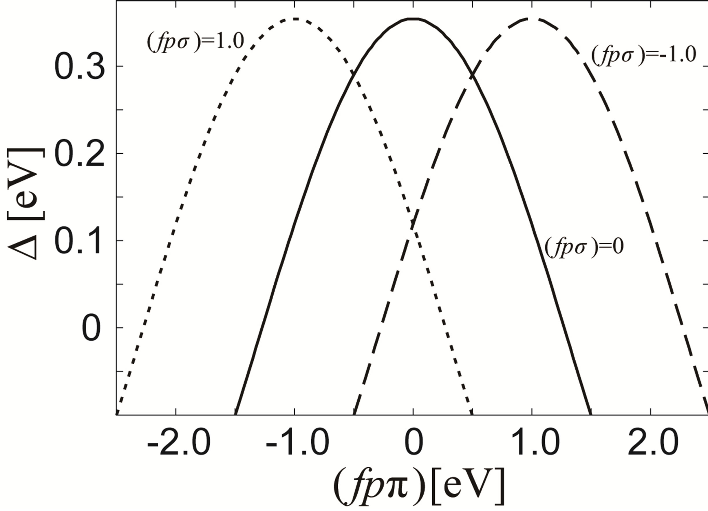
Figure 5. Energy difference Г between Г7 and Г8 states at the Г point in the j = 5/2 bands as a function of (fpπ) for (fpσ) = 0 eV (solid curve), (fpσ) = 1 eV (broken curve), and (fpσ) = −1 eV (dotted curve). A positive Г denotes that the energy of Г7 is larger than that of Г8.
positive in the region of |(fpπ)|~1.2 eV. When we change the value of (fpσ), it is found that the f-p hybridization between actinide Г7 and oxygen 2p orbitals vanishes for the case of (fpπ) = −(fpσ). When (fpπ) is larger or smaller than −(fpσ), the energy of the Г7 state is decreased and ∆ is decreased in any case. Thus, ∆ becomes maximum at (fpπ) = −(fpσ), as shown in Figure 5.
Readers may consider that the absolute value of (fpπ) should not be so small only for the purpose to keep the order of the local CEF states. However, if we increase the absolute value of (fpπ) for (fpσ) = 1 eV, we should remark that the fand p-electron bands are significantly changed from those in the relativistic band-structure calculation results. Thus, from the viewpoints of the local CEF states and the comparison with the band-structure calculations, the reasonable parameters are found in the case of small |(fpπ)| in comparison with (fpσ) = 1 eV.
5. Discussion and Summary
In this paper, we have analyzed the tight-binding model for AnO2 in comparison with the local CEF states and the result of the relativistic band-structure calculations. We have concluded that |(fpπ)| should be small for the case of (fpσ) = 1 eV in our tight-binding model in order to keep the CEF levels at the Г point. We have also emphasized that such a condition coincides with that for the octupole ordering on the basis of the f-p model [20]. Namely, the condition to keep the local Г8 ground state is consistent with the appearance of the ordering of magnetic octupole which is composed of complex spin and orbital degrees of freedom.
Here we provide a comment on the local CEF state in the band-structure calculations. As long as we perform the band-structure calculations with in the LDA, it is found that the Г7 state is lower than the Г8 at the Г point, in contrast to the local CEF state expected from the experiment. In this paper, we have proposed the scenario to control the effect of f-p hybridization on the CEF state, but it should be remarked that in the LDA calculation, we could not obtain insulating state corresponding to the multipole ordering for NpO2 [21]. In order to improve this point, we need to consider the effect of the Coulomb interactions, but it is a serious problem. One way for this problem is to employ the LDA + U method. In fact, it has been reported that the ordered state with octupole and higher multipoles can be reproduced [19], suggesting that the Г8 state is lower than Г7 in the electronic structure. The effective inclusion of the Coulomb interaction is an alternative scenario to understand the CEF state consistent with the experiments.
Although we have not discussed the difference in electronic structure due to the change of actinide ions in this paper, it is naively expected that the difference between Ef and Ep becomes small in the order of Th, U, Np, Pu, Am, and Cm from the chemical trends in actinide ions and the previous band-structure calculations. On the other hand, the change of f-p hybridization among actinide dioxides may play more important roles to explain the effect of the difference in actinide ions. It is an interesting future problem to clarify the key issue to understand the difference in electronic structure of actinide dioxides.
In summary, we have constructed the f-p model in the tight-binding approximation. We have determined the parameters by the experimental results and the relativistic band-structure calculations. It has been concluded that the absolute value of (fpπ) should be small for (fpσ) = 1 eV in order to reproduce simultaneously the local CEF states and the band-structure calculation results. The small value of |(fpπ)| is consistent with the condition to obtain the octupole ordering in the previous analysis of the f-p model. We believe that the present tight-binding model will be useful to extract the essential point of the electronic structure of actinide dioxides from the complicated band-structure calculation results.
6. Acknowledgements
The authors thank S. Kambe, K. Kubo, and Y. Tokunaga for fruitful discussions on actinide dioxides. This work has been supported by a Grant-in-Aid for Scientific Research on Innovative Areas “Heavy Electrons” (No. 20102008) of The Ministry of Education, Culture, Sports, Science, and Technology, Japan and a Grant-in-Aid for Scientific Research (C) (No. 24540379) of Japan Society for the Promotion of Science. The computation in this work has been partly done using the facilities of the Supercomputer Center of Institute for Solid State Physics, University of Tokyo.
REFERENCES
- P. Santini, R. Lémanski and P. Erdös, Advances in Physics, Vol. 48, 1999, pp. 537-653. http://dx.doi.org/10.1080/000187399243419
- T. Hotta, Reports on Progress in Physics, Vol. 69, 2006, pp. 2061-2155. http://dx.doi.org/10.1088/0034-4885/69/7/R02
- P. Santini, S. Carretta, G. Amoretti, R. Caciuffo, N. Magnani and G. H. Lander, Reviews of Modern Physics, Vol. 81, 2009, pp. 807-863. http://dx.doi.org/10.1103/RevModPhys.81.807
- E. F. Westrum Jr., J. B. Hatcher and D. W. Osborne, Journal of Chemical Physics, Vol. 21, 1953, pp. 419-423. http://dx.doi.org/10.1063/1.1698923
- J. W. Ross and D. J. Lam, Journal of Applied Physics, Vol. 38, 1967, pp. 1451-1452. http://dx.doi.org/10.1063/1.1709662
- P. Erdös, G. Solt, Z. Zolnierek, A. Blaise and J. M. Fournier, Physica B + C, Vol. 102, 1980, pp. 164-170.
- J. M. Fournier, A. Blaise, G. Amoretti, R. Caciuffo, J. Larroque, M. T. Hutchings, R. Osborn and A. D. Taylor, Physical Review B, Vol. 43, 1991, pp. 1142-1145. http://dx.doi.org/10.1103/PhysRevB.43.1142
- P. Santini and G. Amoretti, Physical Review Letters, Vol. 85, 2000, pp. 2188-2191. http://dx.doi.org/10.1103/PhysRevLett.85.2188
- J. A. Paixão, C. Detlefs, M. J. Longfield, R. Caciuffo, P. Santini, N. Bernhoeft, J. Rebizant and G. H. Lander, Physical Review Letters, Vol. 89, 2002, Article ID: 187202. http://dx.doi.org/10.1103/PhysRevLett.89.187202
- R. Caciuffo, J. A. Paixão, C. Detlefs, M. J. Longfield, P. Santini, N. Bernhoeft, J. Rebizant and G. H. Lander, Journal of Physics: Condensed Matter, Vol. 15, 2003, pp. S2287-S2296. http://dx.doi.org/10.1088/0953-8984/15/28/370
- S. W. Lovesey, E. Balcar, C. Detlefs, G. van der Laan, D. S. Sivia and U. Staub, Journal of Physics: Condensed Matter, Vol. 15, 2003, pp. 4511-4518. http://dx.doi.org/10.1088/0953-8984/15/26/301
- A. Kiss and P. Fazekas, Physical Review B, Vol. 68, 2003, Article ID: 174425. http://dx.doi.org/10.1103/PhysRevB.68.174425
- Y. Tokunaga, Y. Homma, S. Kambe, D. Aoki, H. Sakai, E. Yamamoto, A. Nakamura, Y. Shiokawa, R. E. Walstedt and H. Yasuoka, Physical Review Letters, Vol. 94, 2005, Article ID: 137209. http://dx.doi.org/10.1103/PhysRevLett.94.137209
- N. Magnani, S. Carretta, R. Caciuffo, P. Santini, G. Amoretti, A. Hiess, J. Rebizant and G. H. Lander, Physical Review B, Vol. 78, 2008, Article ID: 104425. http://dx.doi.org/10.1103/PhysRevB.78.104425
- K. Kubo and T. Hotta, Physical Review B, Vol. 71, 2005, Article ID: 140404. http://dx.doi.org/10.1103/PhysRevB.71.140404
- K. Kubo and T. Hotta, Physical Review B, Vol. 72, 2005, Article ID: 144401. http://dx.doi.org/10.1103/PhysRevB.72.144401
- K. Kubo and T. Hotta, Physica B, Vol. 378-380, 2006, pp. 1081-1082. http://dx.doi.org/10.1016/j.physb.2006.01.428
- P. Santini, S. Carretta, N. Magnani, G. Amoretti and R. Caciuffo, Physical Review Letters, Vol. 97, 2006, Article ID: 207203. http://dx.doi.org/10.1103/PhysRevLett.97.207203
- M.-T. Suzuki, N. Magnani and P. M. Oppeneer, Physical Review B, Vol. 82, 2010, Article ID: 241103. http://dx.doi.org/10.1103/PhysRevB.82.241103
- K. Kubo and T. Hotta, Physical Review B, Vol. 72, 2005, Article ID: 132411. http://dx.doi.org/10.1103/PhysRevB.72.132411
- T. Maehira and T. Hotta, Journal of Magnetism and Magnetic Materials, Vol. 310, 2007, pp. 754-756. http://dx.doi.org/10.1016/j.jmmm.2006.10.127
- G. Amoretti, A. Blaise, R. Caciuffo, J. M. Fournier, M. T. Hutchings, R. Osborn and A. D. Taylor, Physical Review B, Vol. 40, 1989, pp. 1856-1870. http://dx.doi.org/10.1103/PhysRevB.40.1856
- S. Kern, C.-K. Loong, G. L. Goodman, B. Cort and G. H. Lander, Journal of Physics: Condensed Matter, Vol. 2, 1990, pp. 1933-1040. http://dx.doi.org/10.1088/0953-8984/2/7/024
- S. Kern, R. A. Robinson, H. Nakotte, G. H. Lander, B. Cort, P. Watson and F. A. Vigil, Physical Review B, Vol. 69, 1999, pp. 104-106. http://dx.doi.org/10.1103/PhysRevB.59.104
- K. R. Lea, M. J. M. Leask and W. P. Wolf, Journal of Physics and Chemistry of Solids, Vol. 23, 1962, pp. 1381- 1405. http://dx.doi.org/10.1016/0022-3697(62)90192-0
- M. T. Hutchings, Solid State Physics, Vol. 16, 1964, pp. 227-273. http://dx.doi.org/10.1016/S0081-1947(08)60517-2
- J. C. Slater and G. F. Koster, Physical Review, Vol. 94, 1954, pp. 1498-1524. http://dx.doi.org/10.1103/PhysRev.94.1498
- K. Takegahara, Y. Aoki and A. Yanase, Journal of Physics C, Vol. 13, 1980, pp. 583-588. http://dx.doi.org/10.1088/0022-3719/13/4/016
- W. A. Harrison, “Electronic Structure and the Properties of Solids: The Physics of the Chemical Bond,” W. H. Freeman and Company, San Francisco, 1980.
- T. Hotta, Journal of Alloys and Compounds, Vol. 444- 445, 2007, pp. 162-167. http://dx.doi.org/10.1016/j.jallcom.2006.11.028