Applied Mathematics
Vol. 3 No. 1 (2012) , Article ID: 16765 , 6 pages DOI:10.4236/am.2012.31004
Merging Effluent Discharge Plumes from Multiport Diffusers on a Sloping Beach
Department of Mathematics and Statistics, College of Science, Sultan Qaboos University, Muscat, Sultanate of Oman
Email: antonp@squ.edu.om
Received October 29, 2011; revised November 24, 2011; accepted December 3, 2011
Keywords: Effluent Discharge; Mathematical Model; Multiple Outfalls; Multiport Diffuser; Sloping Beach
ABSTRACT
Multiport diffusers are the effective engineering devices installed at the marine outfall systems for the steady discharge of effluent streams from the modern coastal plants, such as municipal sewage treatment, power generation and seawater desalination. A far field mathematical model using a two-dimensional advection-diffusion equation is presented for continuous discharges of effluent streams from multiple outfalls on a uniformly sloping beach with a current parallel to the shoreline. The analytical solutions are illustrated graphically to replicate and capture the merging process of effluent plumes in shallow coastal waters, and then asymptotic approximation will be made to the maximum shoreline’s concentration to formulate effluent discharge plume dilution from a multiport diffuser.
1. Introduction
Along the highly populated coasts of the Arabian Gulf, Gulf of Oman and Red Sea, many large scale municipal sewage treatment and (co-location) power generation and seawater desalination plants are often found to be clustered together [1,2]. Desalination plants generate two products, pure water and brine—a reject concentrate stream. The unwanted brine product is primarily seawater but at a more concentrated level, with a concentration factor of as high as 2.5 more than the typical seawater salinity. Most coastal plants continuously discharge brine streams back into the sea through a submerged outfall, and as a brine stream enters the receiving marine waters, it creates a high salinity plume. Without proper dilution, the brine plume will tend to sink and propagate down the slope for hundreds of meters, harming the ecosystem along the way, and most at risk are the benthic marine organisms living at the sea bottom [2,3]. An engineering solution utilizing the best available technology is required where a multiport diffuser would be installed at the pipe-end to rapidly dilute the concentrate [4-6]. A multiport diffuser is a linear structure consisting of many closely spaced ports designed to discharge a series of effluent streams into the receiving coastal water.
Figure 1 shows two marine outfall systems of the (up to four co-location) Barka power generation and seawater desalination plants in the Gulf of Oman [6]. Each outfall system is designed for a maximum capacity of 122,100 m3/h to discharge the cooling water from the power generation plants and mix it with brine reject stream (and other effluents) from seawater desalination plants. The old (currently in use by the existing Barka I and II plants) outfall pipe length is about 650 m, while the new (not yet been used) outfall pipe length is about 1200 m, and the distance between the two discharge points is 1000 m. The old outfall system comprises of four parallel pipes angled at 62 degrees to the coastline, each with a diameter of 2.5 m, buried at 5 m below the seabed (not visible on the surface) and spaced equally at 4.8 m apart. Each pipe has a 62.4 m long multiport diffuser, consisting of nine ports equally spaced at 7.5 m apart, installed at the end of each outfall pipe. The multiport diffusers are arranged in two nested V shapes as illustrated in Figure 1, and each pair diverges at an angle of 30 degrees on either side of the outfall pipeline. The two internal pipes of length 653 m have its end at a depth of 9 m below the mean sea level, while the other two shorter external pipes of length 582 m end at a depth of 8.4 m. The ports of each diffuser are oriented in an alternating way each with an angle of 20 degrees to the diffuser pipe. The port diameter is 0.7 m and located at 1 m above the seabed, and the ports are oriented upwards with an angle of 10 degrees against the horizontal.
Owing to the highly variable nature of the sea, we do not yet have a full understanding of the mixing processes of effluent discharge plumes, and the use of mathematic-
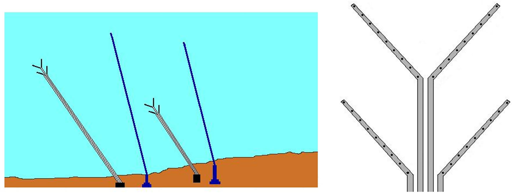
Figure 1. Seawater intake and marine outfall systems of power and desalination plants at Barka, Oman (left), and the multiport diffusers installed at the end of the outfall pipes (right).
cal models has been a key strategy for assessing the potential marine environmental impacts [2,3,6-9]. A clear understanding of these processes is needed so that predictive models can be developed which form the basis of sound engineering design [4]. To demonstrate the effectiveness of a multiport diffuser in diluting the effluent stream, many laboratory and field experimental measurements have been carried out to derive several empirical equations for the effluent plumes formed from the merging of individual port discharges [4,5]. However, no analytical or numerical computations have been done to model and reproduce the interaction and overlapping of multiple effluent plumes. As large scale coastal plants are built predominantly on the sloping sandy beaches, the analytical formulation for the effluent plume dilution of a multiport diffuser discharge is derived here to measure its effectiveness over the single outfall discharge.
2. Mathematical Model Formulation
Immediately after steady release from the multiport diffusers, vigorous and rapid mixing of the effluent stream is governed by the effluent buoyancy, momentum of the discharge and its interaction with the sea currents [3-5]. At the end of this mixing zone stage, adjacent effluent discharge plumes interact with each other and merge to form a rising curtain, which then continues to drift away with the longshore currents [6-9]. Because of relatively shallow water depth, it is observed that the elongated effluent plumes are spreading towards the shoreline and may cause concentration build-up in the coastal waters [7-9].
As we are only concerned with the effect of seabed depth profile, for simplicity the other complexities such as tidal motions, density and temperature are ignored. The shoreline is assumed to be straight and the sea wide, and we assume that the outfall’s effluent plume is vertically well-mixed over the water depth. The coastal (drift) current is assumed to be steady with a speed U and remains in the x-direction parallel to the beach at all times. The dispersion mechanisms are represented by eddy diffusivities, and diffusion in the x-direction is neglected, as the effluent plumes in steady currents become very elongated in the x-direction. The variations in the y-direction of drift current U and coefficient of dispersivity D are assumed as the power functions only of water depth h, and for application, we take U to be proportional to  and D to
 . These scalings are appropriate for a turbulent shallow-water flow over a smooth bed [9-11].
We also consider the effluent stream to be steadily discharged at a rate  from the (original) single outfall at the position
 , where
  is an arbitrary reference water depth; at a different rate
  from the first (new) outfall at the position (

 ); at a rate
  from the second (new) outfall at
 ; and so on, where
  is the outfall’s (offshore) and
  (along the shore) separation distances. For a single outfall, the total effluent load is a function of
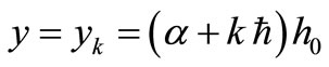
 . As illustrated in Figure 2, these points
 , where
 ,
,  , represent a series of long sea outfalls, each discharging an effluent stream with rate
 . Note that if both values of
  and
and  are small compared to
 , these points represent the engineering design of a multiport line diffuser. For the Barka plant’s multiport diffusers [6],
  m,
m,  m and
m and  m. Furthermore, for a line diffuser with n ports, the total effluent load is distributed into n individual discharges, so that each port discharges equally at a rate
 .
.
In a uniformly sloping beach, the water depth varies

Figure 2. Definition diagram of multiple long sea outfalls.
increasingly linear as , where the beach slope
  and the beach is at
 ; following [7-9] and by applying a linear superposition, the two-dimensional far field advection-diffusion equation for effluent discharge plume concentration
  from the
  multiple outfalls is given by
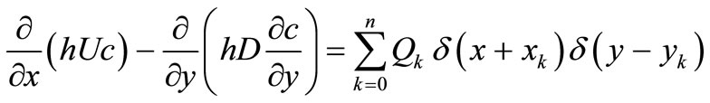 , (1)
, (1)
with the boundary condition  at the beach
 , and
, and  is assumed to be ultimately dissolved into the ocean.
  is the Dirac delta function.
In order to solve Equation (1), the delta function representation of the point source term must be removed as it does not facilitate the solution. However, by doing so, the information about the source strength is also lost. For each long sea outfall at the position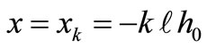 ,
,  discharging effluent stream continuously at a rate
 ,
,
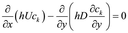 (2)
(2)
is solved separately in the two regions  and
and , and the solutions are then connected by the matching condition
 for all
 .
.
Since no concentration is lost or produced anywhere, and the longitudinal dispersion has been neglected, the solution must also satisfy
 for all
 ;
;
that is, the flux of concentration by advection across any plane perpendicular to the flow direction must be equal to the rate at which concentration is being released from the point source [9]
In terms of dimensionless quantities
 and by setting
 using the Laplace transform
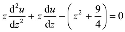
 Equation (2) is transformed into a second-order ordinary differential equation
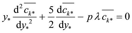 which can be reduced to the modified Bessel’s equation
by writing
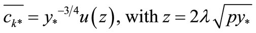 where
where . The general solution in the two regions is given by
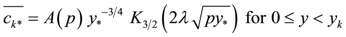 and
and
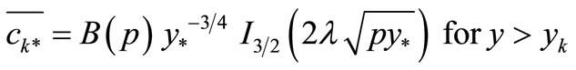 where
where  and
and  are modified Bessel functions [12].
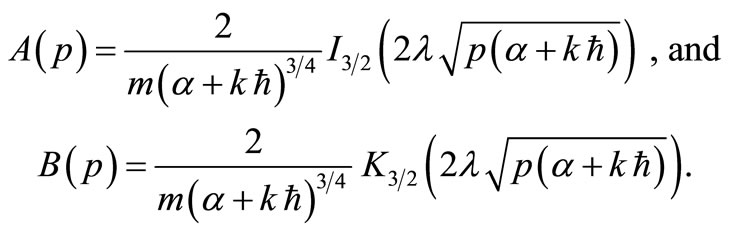
Next, to obtain the particular solution, the functions  and
and  can be determined from the matching conditions

where . From the table of integrals [13]:

and then using the property of the Bessel’s function
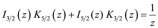 it is found that
Finally, using the inversion of the Laplace transform tabulated in [14], we obtain the exact solution in the form
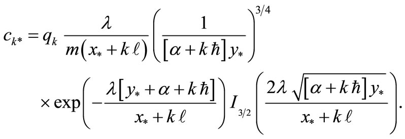
After summing for all concentration  from the
  multiple outfalls, the analytical solution of Equation (1) is given by
 (3)
(3)
As the water depth is gradually decreasing towards the beach, the effluent plumes are elongated and turning towards the beach, and the gentler the beach slope, the higher the buildup in concentration in the shallow water close to the beach [7,8]. This is expected since deeper water is a more efficient transport mechanism. The model parameter  represents the effluent plume elongation in the
  -direction; the larger the values of
 , the more elongated the effluent plumes. To investigate the uncertainty in
 , Figure 3 shows the possible values of
  for some relevant measured values of
  and
and  [8,11] in a shallow water depth
  m. Larger values of
  are mostly due to a stronger drift current
  with less longitudinal dispersivity
 . For the quantitative illustration of the model applications, the values of
  and
and  will be used in all plots.
The other parameters related to the multiple outfalls are  the (original) single outfall (offshore) distance,
  outfall’s (offshore) and
  (along the shore) separation distances. Note that, for a multiport line diffuser with n ports, both values of
  and
and  are smaller than
 , and
, and .
.
3. Multiport Diffuser Discharges
For a large volume effluent discharge, the engineering practice is to distribute the effluent stream over a large expanse by installing a multiport diffuser at the end of a marine outfall to substantially improve the mixing and
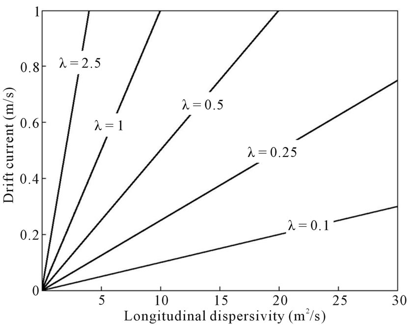
Figure 3. The model parameter λ for water depth h0 = 10 m.
dilution of effluent plumes in the coastal waters [3-6]. By plotting the results of numerical integrations of Equation (3), the merging processes of effluent discharge plumes from a multiport diffuser with 5 ports are reproduced graphically in Figure 4, when the (original) single outfall distance  and the separation distances
  and
and . The peakiness of the contour reflects the overlapping of effluent plumes near the line diffuser; it then drifts along and spreads towards the shoreline.
Again following [7-9], the appropriate measure for assessing the impact of effluent discharges from coastal plants would be the shoreline’s concentration values. In the limit as  and replacing
  in Equation (3) by its asymptotic form [13], we obtain
 (4)
(4)
It is easy to see that for a single outfall when , Equation (4) then reduces to
 .
.
By differentiating, this concentration at the beach has a maximum value of
 which occurs at
  downstream of the outfall.
The compounded concentration at the beach for effluxent discharge from a multiport diffuser with five ports is plotted in Figure 5 for , and for comparison, the concentration at the beach from the single outfall is also shown by the dotted line. The presence of multiple out-

Figure 4. Merging of effluent discharge plumes from a multiport diffuser.
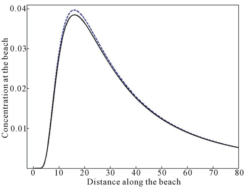
Figure 5. The shoreline’s concentration of effluent discharge from a multiport diffuser.
falls only changes the value of maximum concentration, but not its position. Note that the position of maximum concentration  is proportional to the model parameter
  [8].
[8].
For the quantitative illustration, we consider a perpendicular line diffuser design, where the line diffuser with n ports is placed in the (offshore) y-direction perpendicular to the current direction, and it consists of a series of ports equally spaced by the offshore separation distance . The maximum compounded concentration at the beach can be approximated by substituting
 [8]. Using the fact that
  and
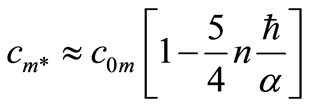
and  is small, we can linearize Equation (4), to approximate the maximum value of shoreline’s concentration as
 . (5)
. (5)
Finally, after summing for n ports, the maximum concentration Equation (5) reduces to
 , (6)
, (6)
where  is the (total) length of the line diffuser. As the number of ports increases and the single outfall distance gets longer, the maximum shoreline’s concentration Equation (6) gets smaller than that of the single outfall value.
Figure 6 shows the effluent plume (additional) dilution (above that of the single outfall value), which is defined as the ratio of the initial concentration at the outfall discharge point to that at a given location, when  for three values of
 , 0.01 and 0.015. In particular for a 9-port line diffuser, an additional dilution of 1.3 (above the single outfall dilution of 25.2) is obtained for
 , and it increases to 4.4 as
  increases to 0.015. Similarly, for
 , an additional dilution of 8.4 can be achieved by increasing the number of ports to 21. This finding is in agreement with the general fact that a multiport diffuser improves the mixing of effluent plumes substantially with additional dilutions of up to about 20, mainly because the individual plumes are collapsed and swept away rapidly by the current.
4. Conclusion
The multiport diffusers are commonly designed in the form of a linear structure consisting of many closely spaced ports or nozzles which discharge a series of effluent plumes into the receiving coastal waters. Such diffusers have increasingly been installed at the end of marine outfall pipelines from the modern coastal plants as part of an engineering solution to minimize the potential environmental impacts of a large volume of effluent discharges. A mathematical model is developed to replicate and capture the process of merging effluent dis-
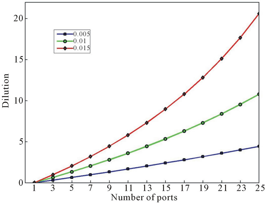
Figure 6. Dilution of effluent discharge plume from a perpendicular line diffuser.
charge plumes from a multiport diffuser on a sloping beach with a current parallel to the shoreline. The maximum diffuser-induced shoreline concentration is then formulated, and the results for the perpendicular line diffuser (to the current direction) are in agreement with the fact that a multiport diffuser is capable of thoroughly mixing and diluting the effluent with additional dilutions of up to about 20 (above that of the single outfall value).
5. Acknowledgements
The author is grateful to Sultan Qaboos University for an Internal Grant IG/SCI/DOMS/10/11 which provided financial support for this work and to Dr. Hamdi Al-Barwani for his support and many helpful discussions.
REFERENCES
- S. Lattemann and T. Hopner, “Environmental Impact and Impact Assessment of Seawater Desalination,” Desalination, Vol. 220, No. 1-3, 2008, pp. 1-15. doi:10.1016/j.desal.2007.03.009
- D. A. Roberts, E. L. Johnston and N. A. Knott, “Impacts of Desalination Plant Discharges on the Marine Environment: A Critical Review of Published Studies,” Water Research, Vol. 44, No. 18, 2010, pp. 5117-5128. doi:10.1016/j.watres.2010.04.036
- T. Bleninger and G. H. Jirka, “Modelling and Environmentally Sound Management of Brine Discharges from Desalination Plants,” Desalination, Vol. 221, No. 1-3, 2008, pp. 585-597. doi:10.1016/j.desal.2007.02.059
- G. H. Jirka, “Integral Model of Turbulent Buoyant Jets in Unbounded Stratified Flows. Part 2. Plane Jet Dynamics Resulting from Multiport Diffuser Jets,” Environmental Fluid Dynamics, Vol. 6, 2006, pp. 43-100.
- P. J. W. Roberts and X. Tian, “New Experimental Techniques for Validation of Marine Discharge Models,” Environmental Modeling and Software, Vol. 19, No. 7-8, 2004, pp. 691-699. doi:10.1016/j.envsoft.2003.08.005
- A. Purnama, H. H. Al-Barwani, T. Bleninger and R. L. Doneker, “CORMIX simulations of brine discharges from Barka plants, Oman,” Desalination and Water Treatment, Vol. 32, 2011, pp. 329-338. doi:10.5004/dwt.2011.2718
- H. H. Al-Barwani and A. Purnama, “Re-Assessing the Impact of Desalination Plants Brine Discharges on Eroding Beaches,” Desalination, Vol. 204, No. 1-3, 2007, pp. 94-101. doi:10.1016/j.desal.2006.03.536
- H. H. Al-Barwani and A. Purnama, “Analytical Solutions for Brine Discharge Plumes on a Sloping Beach,” Desalination and Water Treatment, Vol. 11, 2009, pp. 2-6. doi:10.5004/dwt.2009.835
- A. Kay, “The Effect of Cross-stream Depth Variations upon Contaminant dispersion in a Vertically Well-Mixed Current,” Estuarine and Coastal Shelf Science, Vol. 24, No. 2, 1987, pp. 177-204. doi:10.1016/0272-7714(87)90064-3
- R. Smith, “Longitudinal Dispersion of Buoyant Contaminant in a Shallow Channel,” Journal of Fluid Mechanics, Vol. 78, No. 4, 1976, pp. 677-688. doi:10.1017/S0022112076002681
- D. W. Ostendorf, “Longshore Dispersion over a Flat Beach,” Journal of Geophysical Research, Vol. 87, No. C6, 1982, pp. 4241-4248. doi:10.1029/JC087iC06p04241
- G. M. Murphy, “Ordinary Differential Equations and Their Solutions,” D. Van Nostrand, London, 1960.
- I. S. Gradshteyn and I. Ryzhik, “Tables of Integrals, Series and Products,” Academic Press, London, 1980.
- A. Erdelyi, W. Magnus, F. Oberhettinger and F. G. Tricomi, “Tables of Integral Transforms,” Vol. 1, McGraw Hill, London, 1954.