Wireless Engineering and Technology
Vol.3 No.4(2012), Article ID:24187,4 pages DOI:10.4236/wet.2012.34030
Electromagnetic Band Gap Loaded Square Waveguide Band-Pass Filter for Dual-Polarized Application
![]()
Institute of Electronic Science & Engineering, Nanjing University of Posts & Telecommunications, Nanjing, China.
Email: windring_tony@126.com
Received September 4th, 2012; revised October 2nd, 2012; accepted October 13th, 2012
Keywords: Electromagnetic Band Gap (EBG); Band-Pass Filter (BPF); Dual-Polarized; Square Waveguide
ABSTRACT
An Electromagnetic Band Gap (EBG) loaded square waveguide Band-Pass Filter (BPF) is proposed in this paper. It’s simply composed by symmetrically loading periodical metal diaphragms on each wall of a square waveguide. The influences of insert sizes and loading periods on the overall BPF performances are analyzed. Experimental results agree well with those predicted. 6 GHz pass-band with insert loss less than 1 dB, 2.5 GHz stop-band and larger than 25 dB polarization isolation can be obtained. The BPF can be applied in dual-polarized waveguide-based antenna-feed systems.
1. Introduction
EBG structures have been receiving increasing attention in microwave applications for their good performances and compact sizes. They’re composed by adding periodical inductive, capacitive or resonant loads in planar substrates (named Substrated Integrated Waveguide [1, 2]) or waveguide housings(named EBG waveguide [3,4]). Generalized scattering matrix, equivalent circuit analysis and commercial EM software can be employed to obtain characteristics of periodical cells, whole EBG waveguide and related antennas, components design. For example, SIW [1,2] can be applied in high speed and high frequency systems. EBG waveguides filter possesses better characteristics and smaller dimensions than traditional E-plane filter [3], and its stop-band characteristics can be much improved [4] by parallel-double-loading style. Woodpile EBG waveguides [5-7] can be applied in the design of antennas, bends and power dividers, but the structures are too complicated and the volumes are too large.
Whatever only a little material is available about EBGloaded square waveguide designs. To be used in highpowered dual-polarized systems, EBG loaded square waveguide BPFs are analysed in this paper. All the metal inserts are symmetrically and periodically loaded, with shape of round crown and rectangular bottom, to achieve much more smooth transition and much better matching. Simulation and measured results are presented in good agreement, followed by detailed influences explanation about the inserts dimensions and loading period on the overall performances. Good characteristics can be obtained and the filter can be conveniently applied in dual polarization systems.
2. Configuration Description
Just as in traditional full-height E-plane filters, the periodical planes in proposed EBG-loaded square waveguide filter also bring different influences to different modes, forming the desired filter characteristics. The periodically loading structures possess similar specialties as photon crystals and the loading period is concerned with Bragg reflections to produce band-gaps corresponding to the dominant or higher order mode. The relationship between the lower cutoff frequency of band-gap fbc, loading period p and waveguide dimension a can be written as
 (1)
(1)
Figures 1(a) and (b) show the proposed configuration of EBG loaded square waveguide BPF, where a, w, h and p represent the waveguide dimension, inserts width, height and loading period respectively. The inserts width w is set to be 2 mm to obtain the best stop-band characteristics and the inserts thickness t is set to be 200 um. The waveguide dimension a is 20 mm for X-band operation with dominant mode cutoff frequency 7.5 GHz and the loading period p can be initialized according to Equation (1) and then optimized by software simulations to get the most suitable value. Otherwise, all the metal inserts are all the shape of round-crown and rectangular-bottom,
Figure 1. Configuration of EBG square waveguide BPF.
being arrayed on the symmetry axe of each wall. This inserts loading style here can provide better matching between homogenous square waveguide EM mode and EBG propagation mode compared with completely rectangular form.
In traditional EBG waveguides, the insert cells on the opposite walls can be intrinsically equivalent to L-C series resonators in shunt topology. While in the proposed case the four inserts in one cell can not be easily divided into two independent sets of so-called L-C resonators?
Observed from Figure 2, which shows the Excitation electro-field and field distribution on cross-section where insert plane positioned, the answer to the above question is “yes” and the BPF can be compatible in broadband, dual-polarized systems. Then the rounded-crowned shapes can reduce electromagnetic coupling and much better pass-band, especially band-gap, characteristics can be obtained.
3. Simulation Results and Analysis
In this study, equivalent circuit analysis is firstly employed to obtain initial structural parameters, including the inserts dimensions and loading period. Then frequency sweep and parametric optimization are performed by EM software to obtain characteristics comparison curves and their variation rules versus structural sizes. Only having little influence on the overall performance, and taking simulation and manufacture convenience into account as well, the inserts width and thickness are respectively set to be 2 mm and 0.2 mm. The inserts height and loading period are treated as variables for parametric analysis. Two sets of quantitative simulations are respectively carried out for the case of fixed insert height, changing loading period and the contrary case.
3.1. Simulation 1: Fixed Insert Height (4 mm)
Figure 3 shows the BPF insert loss and return loss characteristics variation curves corresponding to differ-
Figure 2. Excitation electro-field and field distribution on the cross-section where insert plane positioned.
Figure 3. Return loss and insert loss characteristics of EBG-loaded square waveguide BPF with insert height 4 mm. Loading period ranges 7.5 mm - 8.5 mm with step of 0.25 mm.
ent loading periods, ranging from 7.50 mm to 8.50 mm with the step of 0.25 mm. It can be observed that the upper cutoff frequency, fuc, of the pass-band decreases with the increase of loading period, though the shift magnitude is very small. In two independent cases when the loading period is 7.50 mm - 8.00 mm and 8.25 mm - 8.50 mm, the return loss curves are almost overlapped.
As simulation results show, the band-gap performances appear very bad for those loading periods are less than 7.50 mm. Then for the cases of loading periods are greater than 8.50 mm, the pass-band widths are very narrow and the overall performances also greatly deteriorated. Therefore, the comparatively best choice of loading period with the fixed insert height 4 mm is 8 mm, with characteristic curves plotted in circled line.
3.2. Simulation 2: Fixed Loading Period (8 mm)
Figure 4 shows the BPF insert loss and return loss characteristic variation curves corresponding to different inserts heights, ranging from 3.50 mm to 4.50 mm with the step of 0.25 mm. Some similar phenomena as in the former case can be observed. Otherwise, the higher the inserts height is, the larger the upper cutoff frequency of pass-band is, except that the shift magnitude of frequency caused by the alteration of inserts heights is much larger. Then the comparatively best choice of insert height with loading period 8 mm is 4 mm, in good agreement with the former conclusion, as plotted in circled line.
3.3. Dual-Polarized Characteristics
To be used in dual-polarized applications, the simulated polarization isolation is also considered, showed in Figure 5. Dash-dotted and dotted line show the polarization isola-tion among different BPF ports, better than 28 dB. Solid line shows the polarization isolation between two per-pendicular polarized modes of the same port, better than 40 dB. Then in the stopband of operating polarized mode, polarized isolation of better than 40 dB can be obtained. All these characteristics are very useful for dual-polarization applications.
It can be concluded that symmetrically loading periodical planes in square waveguide are quite available and effective for microwave pass filter application. The inserts shape, rounded-crown and rectangular-bottom, and their loading style make this loading style much more effective. On the other hand, the insert height and loading period produce similar influences on the whole characteristics of EBG loaded BPF, therefore, proper combination of these two parameters is insert height 4 mm and loading period 8 mm. The pass-band ranges from 7.5 GHz to 14 GHz with the in-band insert loss less than 0.5 dB. The stop-band ranges from 14 GHz to 16.5 GHz with the least out-band attenuation less than –45 dB.
4. Measured Results
For the BPF manufacture, only ordinary fabrication and orientation precision are enough to achieve desired performance, which can greatly reduce production cost. Integrative planes and orientation screws are employed to insure mounting convenience and orientation precision. Figure 6 shows practical photo of EBG square waveguide BPF. Figure 7 shows the measured S-parameters curves and Figure 8 is the measured polarization isolation curves.
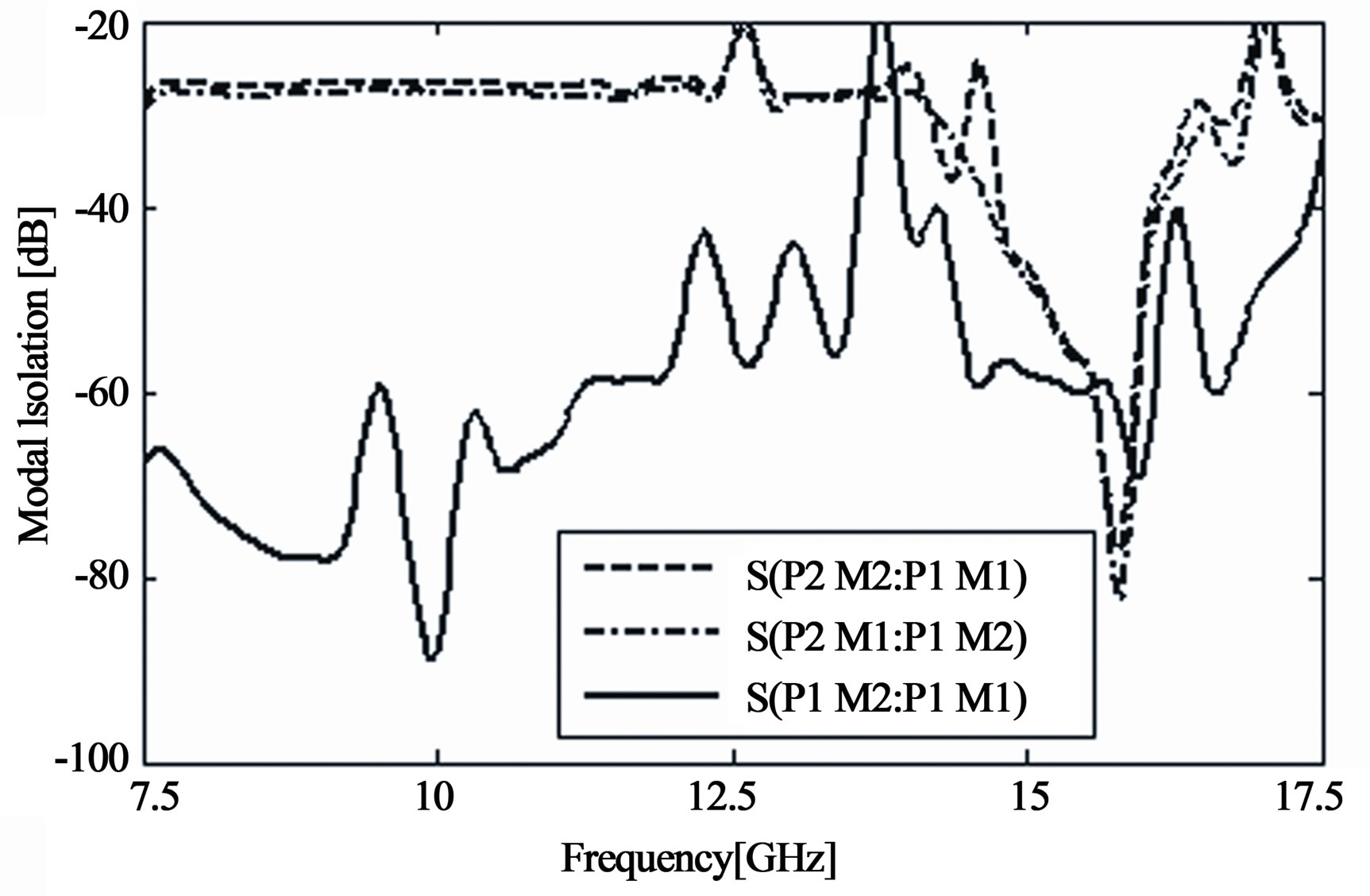
Figure 5. Polarization isolation of EBG-loaded square waveguide BPF with loading period 8 mm and insert height 4 mm.
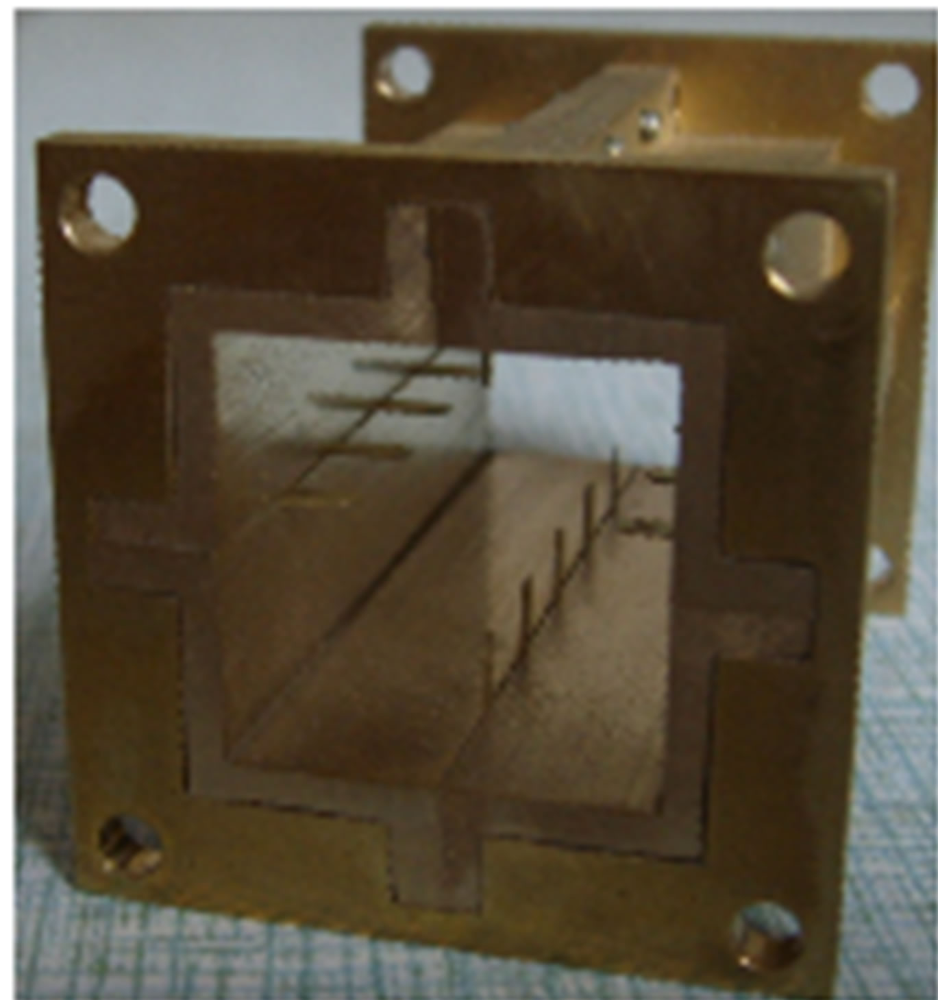
Figure 6. Practical photo of EBG loaded BPF.
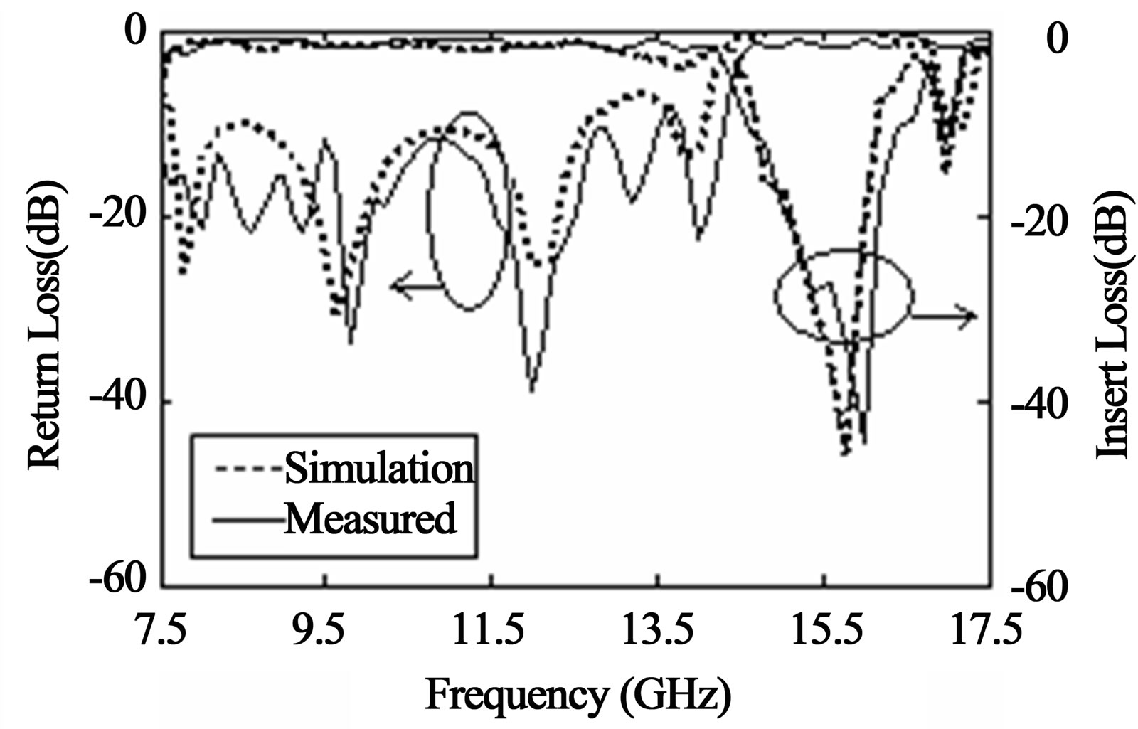
Figure 7. Comparison of measured and theoretical results.
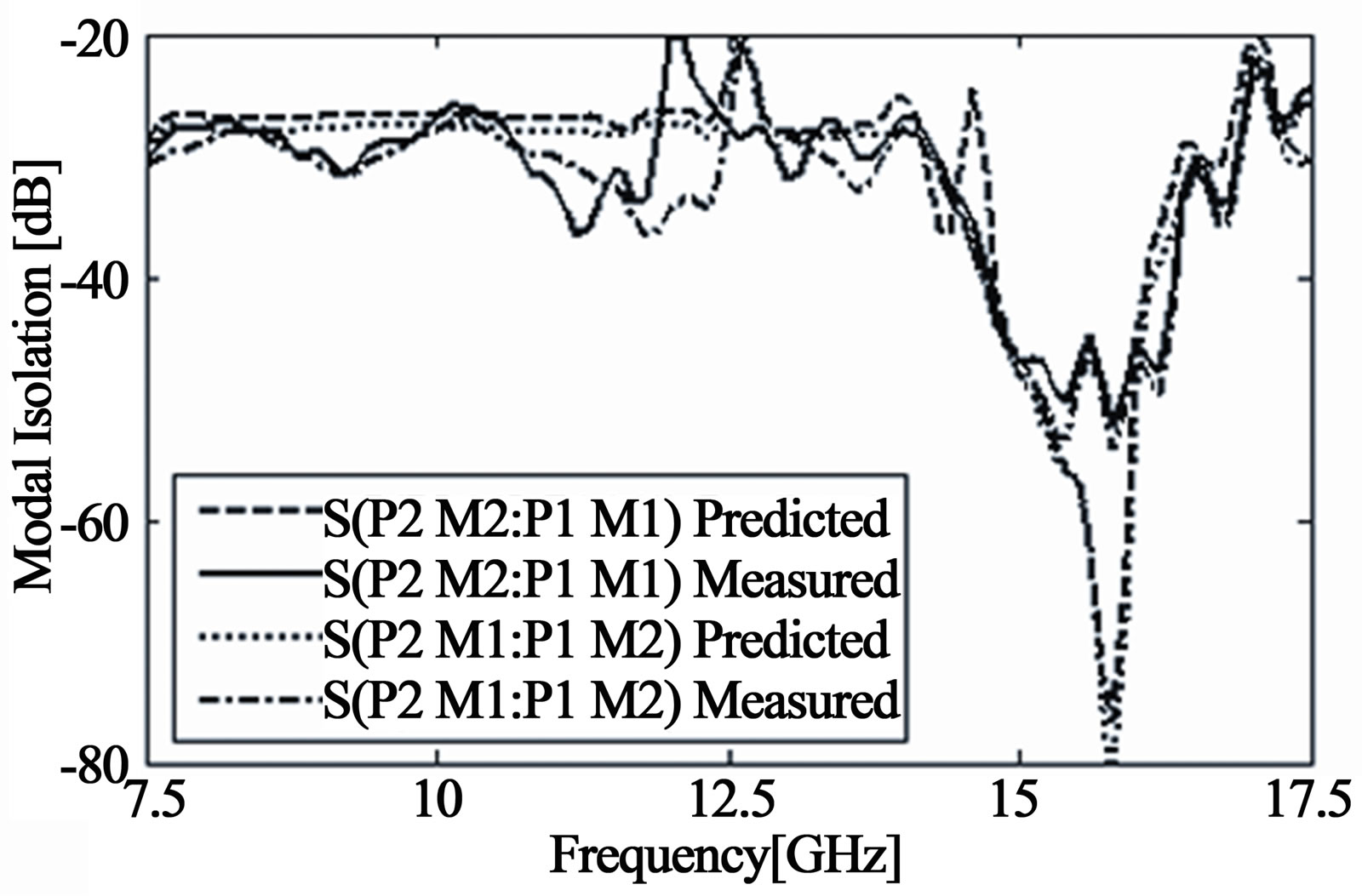
Figure 8. Measured polarization isolation of EBG loaded square waveguide BPF.
Observed from these diagrams, some fluctuations and small characteristics deterioration appear in the measured results, such as 0.8 dB pass-band insert loss, 20 dB polarization isolation at several frequencies and best polarization isolation 40 dB, which is much smaller than the simulated value 85 dB. These may be caused by imperfectly smooth surfaces, conductor loss, artificial assembling error and multi-transitional measurement. Otherwise, the inserts may be not so straightly in one line or perfectly perpendicular to waveguide walls. Taking all the factors into account, good agreement can be regarded as being achieved between theoretic and experimental results.
5. Conclusion
A novel EBG-loaded square waveguide BPF with good performances is described, by symmetrically loading periodical diaphragms on each axe of square waveguide. Simulation and experimental results are presented in good agreement, followed by detailed explanation about the influence of inserts dimensions and loading period on the whole BPF characteristics. Good performances are obtained, including 6 GHz pass-band with the in-band insert loss less than 1 dB, 2.5 GHz stop-band with the largest out-band attenuation greater than 45 dB and larger than 20 dB polarization isolation. This filter can be conveniently compatible in dual-polarized waveguidebased antenna-feed systems.
6. Acknowledgements
I would like to express my sincere friend supervisor, Professor Bo Yaming for his kindly encouragement and valuable suggestions in writing this paper. More appreciations will offer to thank the sponsor, Nature Science Found of Nanjing University of Posts & Telecommunications (NY211057) and Scientific Research Found for Introduction of Talents Plan of Nanjing University of Posts & Telecommunications (NY209008), for the opportunity to work on this project.
REFERENCES
- A. Suntives and R. Abhari, “Investigation of the Performance of an EBG Waveguide-Based Interconnect Used as a High-speed Serial Link,” 2006 IEEE Workshop on Signal Propagation on Interconnects, Berlin, 9-12 May 2006, pp. 71-74.
- A. Suntives and R. Abhari, “Transition Structures for EBG Waveguide-Based Interconnects,” IEEE 14th Topical Meeting on Electrical Performance of Electronic Packaging, 24-26 October 2005, pp. 147-150.
- G. Goussetis, A. P. Feresidis and P. Kosmas, “Efficient Analysis, Design, and Filter Applications of EBG Waveguide with Periodic Resonant Loads,” IEEE Transactions on Microwave Theory and Techniques, Vol. 54, No. 11, 2006, pp. 3885-3892. doi:10.1109/TMTT.2006.883648
- Y.-M. Tang, Y.-M. Yu and W. Wu, “Improved EBGLoaded Waveguide Low-Pass Filter,” Microwave and Optical Technology Letters, Vol. 50, No. 8, 2008, pp. 2090-2093. doi:10.1002/mop.23608
- A. R. Weily, K. P. Esselle, T. S. Bird and B. C. Sanders, “A Woodpile EBG Sectoral Horn Antenna,” IEEE Antennas and Propagation Society International Symposium, Vol. 4B, No. 1, 2005, pp. 323-326.
- A. R. Weily, K. P. Esselle, T. S. Bird and B. C. Sanders, “Linear Array of Woodpile EBG Sectoral Horn Antennas,” IEEE Transactions on Antennas and Propagation, Vol. 54, No. 8, 2006, pp. 2263-2274. doi:10.1109/TAP.2006.879181
- A. R. Weily, K. P. Esselle, T. S. Bird and B. C. Sanders, “Experimental Woodpile EBG Waveguides, Bends and Power Dividers at Microwave Frequencies,” Electronics Letters, Vol. 42, No. 1, 2006, pp. 32-33. doi:10.1049/el:20063206