Wireless Engineering and Technology
Vol.4 No.4(2013), Article ID:38644,4 pages DOI:10.4236/wet.2013.44026
A U-Shaped UWB Antenna with Band-Notched Performance
![]()
Department of Electronics and Communication Engineering, Urmia University, Urmia, Iran.
Email: aliakbar.hosseinzadeh@gmail.com
Copyright © 2013 Aliakbar Hosseinzadeh et al. This is an open access article distributed under the Creative Commons Attribution License, which permits unrestricted use, distribution, and reproduction in any medium, provided the original work is properly cited.
Received July 29th, 2013; revised September 2nd, 2013; accepted September 16th, 2013
Keywords: Ultra-Wideband Antenna (UWB); Slot; Slit; Band-Notched
ABSTRACT
An ultra-wideband antenna with controllable band-notched is presented. Two semi-ellipses with different radiuses are subtracted to result in the main patch. By varying inner and outer radiuses, much more enhancement in bandwidth occurred. A U-shaped slot is used to make band-stop performance. Measured S11 is ≤−10 dB over 2.3 - 5 GHz and 6.1 - 15.1 GHz.
1. Introduction
As stated in Federal Communications Commission (FCC), the ultra-wideband (UWB) radio systems use the designated 3.1 - 10.6 GHz frequency band. Due to this large frequency range, there would be interference with WLAN technologies such as IEEE 802.11 a (5.15 - 5.35 GHz, 5.725 - 5.825 GHz) [1]. Therefore, it is desirable to attenuate this interference by inserting some frequency selectivefilters. Various UWB antennas with band-notched characteristic have been reported to avoid interferences, such as TwoL-shaped quarter-waveguide resonators coupled to the ground plane with two shorting tracks at the sides of the antenna [2], split ring resonator [3], U-shaped slots and E-shaped slot [4], rectangular slots and 4-shaped slots [5], inverted U-shaped slots and Hshaped slot [6], C-shaped slots [7], and multi-U-shaped slots [8].
In this structure, Coplanar Waveguide Grounded (CPWG) transmission line is used due to its characteristics, such as low radiation loss, low dispersion and ability to integration with active solid-state devices.
In this paper, a U-shaped patch with inner radius of R1 and outer radius of R2 is presented. By adjusting different values of R1 and R2, bandwidth enhancement is achieved. A U-shaped slot is used to obtain band-stop performance. By properly adjusting the parameters, it is possible to find desirable bandwidth and to center frequency of notched band.
This paper includes following sections. In the next section, the geometry of the proposed antenna is described. Discussions and antenna performance are indicated in Section 3 and the measured results are provided in Section 4.
2. Antenna Configuration
Geometry of the proposed antenna is illustrated in Figure 1. A smaller semi-ellipse with radius of R1 is subtracted from a larger one with radius of R2 that results in a U-shaped patch. The inner radius (R1) and the outer one (R2) are equal to 8 mm and 18 mm, respectively. CPWG structure is used for antenna feedline that makes it suitable for integrating with the other components. The parameters of this feedline are chosen so that the impedance of feedline is equal to 50 Ω and is matched with SMA connector.
This structure is symmetrical to the longitudinal axis that exhibits appropriate radiation patterns.
The antenna is printed on an inexpensive FR4 with dielectric constant of 4.4 and thickness of 1 mm. A Ushaped slot is inserted in the patch that provides bandnotch performance. The width of slot has been optimized and is equal to 0.5 mm. The overall size of the antenna is 40 × 40 mm2. A conducting ground plane with size of 20 × 40 mm2 is also printed on the other side of the substrate.
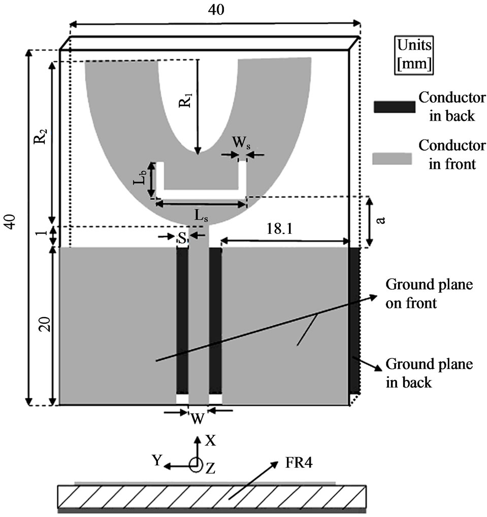
Figure 1. Geometry of the proposed CPWG-fed antenna with U-shaped slot.
3. Antenna Discussion
The parameters of the proposed antenna are simulated and optimized using HFSS v13. By applying U-shaped patch, two important parameters (R1, R2) are obtained. Different values of these parameters result in different lengths of current paths that can affect upper and lower frequencies of bandwidth. It is clear that variation of outer radius (R2) can alter the area of patch more than the inner one. In other case R2 variations alter the gap between lower edge of radiating patch and top edge ofground plane and affect impedance matching. Figure 2 shows R2 effect on antenna bandwidth. It can be observed; by increasing R2 larger bandwidth can be obtained. In this study the outer radius is set equal to 18 mm.
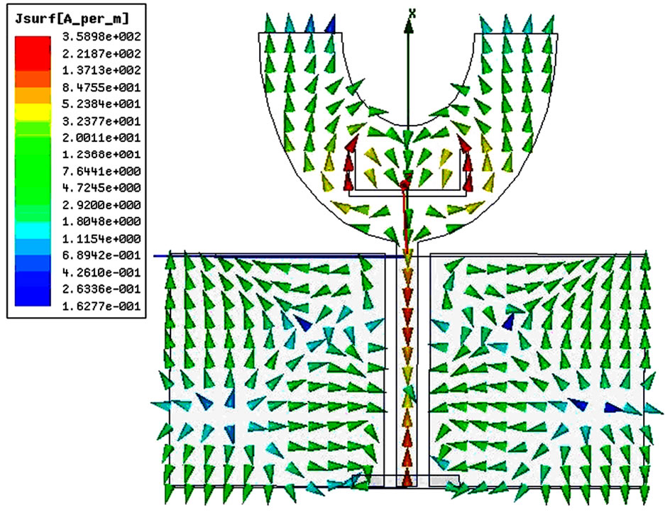
In order to achieve notched frequency at 5.5 GHz, a U-shaped slot is inserted in the patch. The width has been optimized, and then is set equal to 0.5 mm. Its length is about half of the wavelength of the notched frequency [9]. As an important parameter to control the center frequency of the notched band, the length of the U-shaped slot is investigated in Figure 3. It can be seen that by increasing the total length of slot, the notch frequency decreases monotonically. Position of slot plays an important role on the antenna performance. Figure 4 illustrates the effect of slot position on the bandwidth of notch. This figure shows that if slot position moves downward, it causes wider notch bandwidth. Figure 5 shows current distribution on the feedline, side grounds and main patch at 5.9 GHz and 8.4 GHz frequency. In comparison with
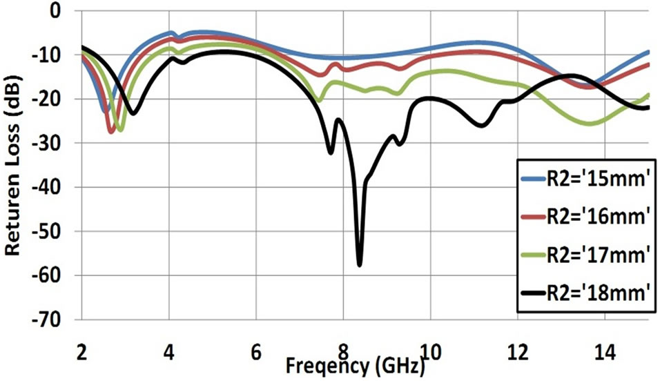
Figure 2. Simulated return loss versus frequency characteristics for various sizes of R2.
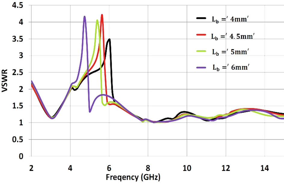
Figure 3. Simulated VSWR vs. frequency for different Lb.
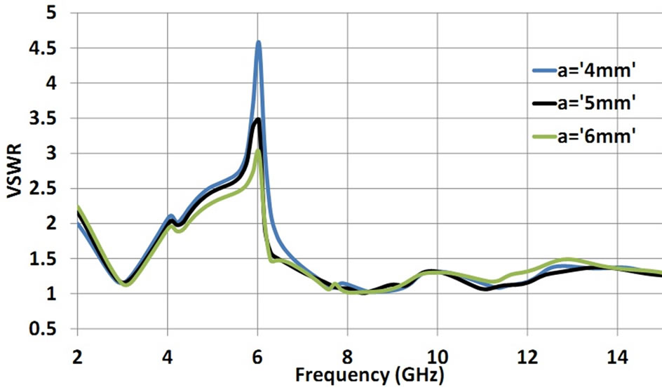
Figure 4. Simulated VSWR vs. frequency for differenta.
8.4 GHz, it is obvious that at 5.9 GHz (notch frequency) the current paths around the U-shaped slot are in opposite directions that results in a notch performance at this frequency.
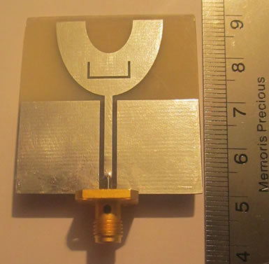
The antenna has been fabricated according to its final optimized parameters. These parameters are provided in Table 1. The proposed antenna structure was fabricated, as shown in Figure 6. The fabricated prototype is measured by Agilent Technologies, E8361Cnetwork analyzer.
The measured and simulated return loss results are indicated in Figure 7. It is evident from this figure that antenna can cover 2.3 - 15.1 GHz with stop band from 5
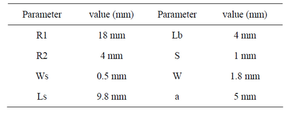
Table 1. Geometrical parameters of the proposed antenna.
 (a)
(a)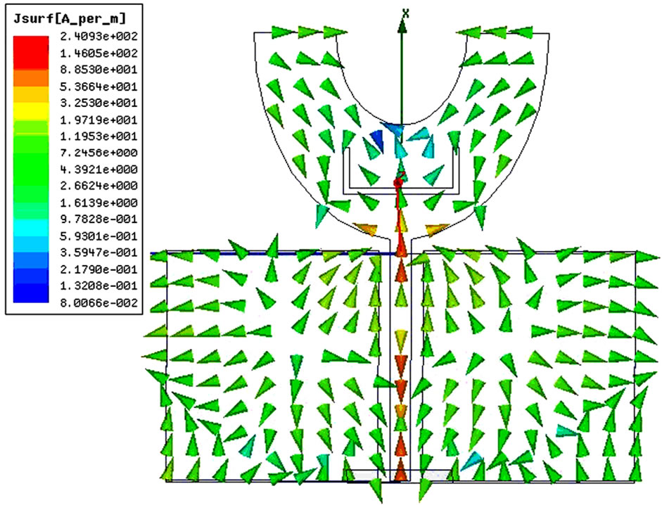 (b)
(b)
Figure 5. Simulated current surface distribution at a) 5.9 GHz, b) 8.4 GHz.
GHz to 6.1 GHz.
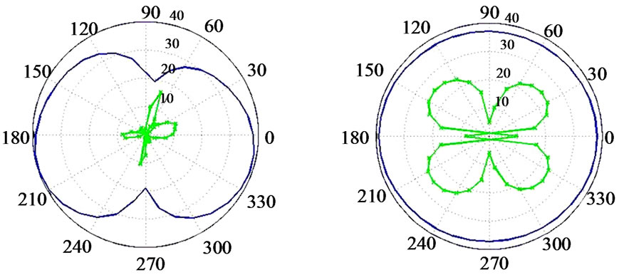
Radiation patterns of the proposed antenna in H-plane and E-plane at sampling frequencies of 3, 5, and 8 GHz are plotted in Figure 8. These patterns are measured in the anechoic chamber of Prof. Morshed Antenna laboratory. At lower frequencies, it is seen that our proposed design exhibits an omni-directional profile for the Hplane and a bi-directional one for the E-plane. With the increase of frequency, the proposed antenna becomes more directive.
 (a)
(a)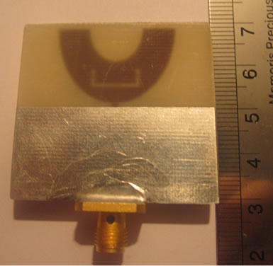 (b)
(b)
Figure 6. Photograph of proposed U-shaped antenna (Fabricated prototype). (a) Front View (b) Back View.
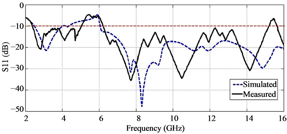
Figure 7. Simulated and measured S11 of the proposed Ushaped antenna.
 (a)
(a) (b)
(b)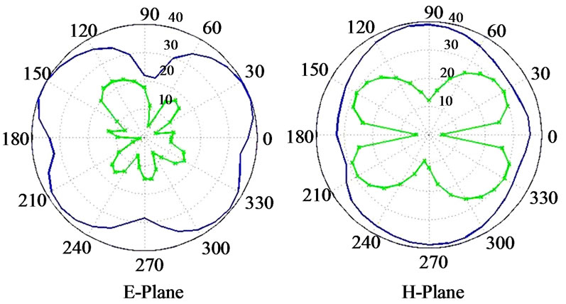 (c)
(c)
Figure 8. Radiation pattern of the proposed antenna (a) f = 3 GHz, (b) f = 5 GHz, (c) f = 8 GHz.
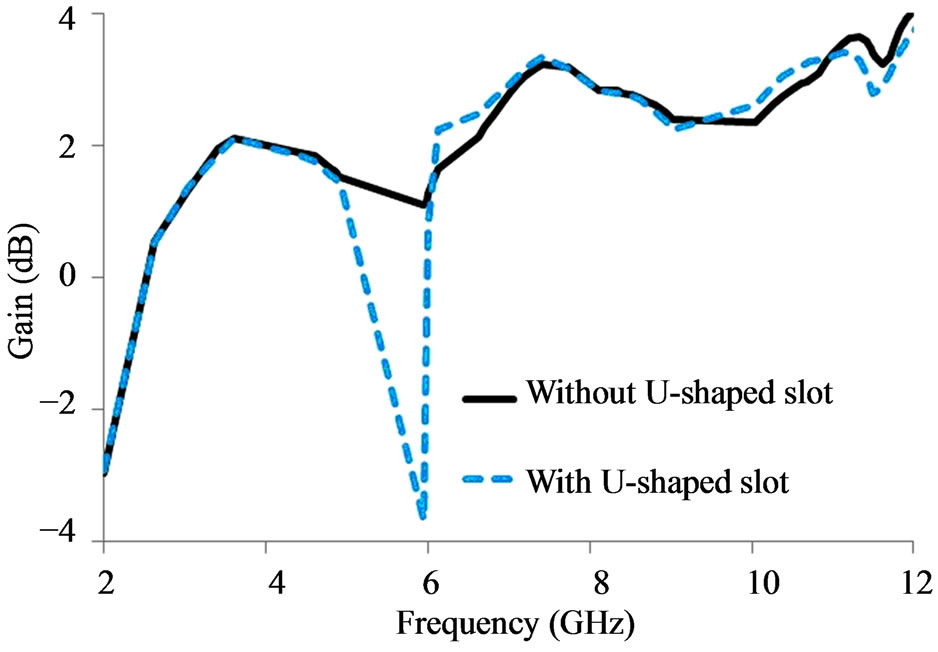
Figure 9. Gain of proposed antenna.
The gains of the proposed antenna with and without Ushaped slot areplotted in Figure 9, showing an acceptable flat gain over 3 - 10 GHz while low radiation level in the notched band.
4. Conclusion
An UWB U-shaped antenna with band notch characteristic has been presented and discussed. U-shaped patch has been used to improve antenna bandwidth. By embedding a U-shaped slot, band notch performance is achieved. The stop band is over 5 - 6.1 GHz. The center frequency of stop-band and its bandwidth can be controlled by length and width of slot, respectively. The antenna was fabricated and its performance has been tested. Good agreement is achieved between the simulated and measured results.
REFERENCES
- FCC First Report and Order on Ultra-wideband Technology, FCC, 2002.
- H. J. Lak, C. Ghobadi and J. Nourinia, “A Novel Ultra-Wideband Monopole Antenna with Band-Stop Characteristic,” Wireless Engineering and Technology, Vol. 2, NO. 4, 2011, pp. 235-239. http://dx.doi.org/10.4236/wet.2011.24032
- Q. X. Chu and Y. Y. Yang, “A Compact Ultra Wideband Antenna with 3.4/5.5 GHz Dual Band-Notched Characteristics,” IEEE Transactions on Antennas and Propagation, Vol. 56, No. 12, 2008, pp. 3637-3644.
- Y. S. Li, X. D. Yang, C. Y. Liu and T. Jiang, “Compact CPW-Fed Ultra-Wideband Antenna with Dual Band-Notched Characteristics,” Electronic Letters, Vol. 46, No. 14, 2010, pp. 967-968. http://dx.doi.org/10.1049/el.2010.8386
- J. B. Jiang, Z. H. Yan and J. Y. Zhang, “Dual Band-Notched Ultra-Wideband Printed Antenna with Two Different Typed Slots,” Microwave Optical Technology Letters, Vol. 52, No. 9, 2010, pp. 1930-1933. http://dx.doi.org/10.1002/mop.25411
- W. S. Lee, D. Z. Kim, K. J. Kim and J. W. Yu, “Wideband Planar Monopole Antennas with Dual Band-Notched Characteristics,” IEEE Transactions on Microwave Theory Technology, Vol. 54, No. 3, 2008, pp. 2800-2806.
- J. M. Beygi, J. Norinia and C. Ghobadi, “Compact UltraWideband with Dual Band-Stop Characteristic,” IEICE Electronic Express, Vol. 7, No. 9, 2010, pp. 596-600. http://dx.doi.org/10.1587/elex.7.596
- L. Luo, Z. Cui, J. P. Xiong, X. M. Zhang and Y. C. Jiao, “Compact Printed Ultra-Wideband Monopole Antenna with Dual Band-Notch Characteristic,” Electronic Letters, Vol. 44, No. 44, 2008, pp. 1387-1388.
- Y. Y. Lu, H.-J. Lam and J. Bornemann, “Coplanar Printed-Circuit Antenna with Band-Rejection Elements for Ultra-Wideband Filtenna Applications,” IEEE Antennas and Propagation Society International Symposium, AP-S 2008, San Diego, 5-11 July 2008, pp. 1-4.

