Smart Grid and Renewable Energy
Vol.4 No.2(2013), Article ID:31923,8 pages DOI:10.4236/sgre.2013.42019
Temperature Control in a PV-WIND Medical Herb Dryer System
![]()
PV Cells Department, Electronics Research Institute, Cairo, Egypt.
Email: abdelshafyn@yahoo.com, emadsweelem@yahoo.com, fatenhf@yahoo.com
Copyright © 2013 Abdel-Shafy A. Nafeh et al. This is an open access article distributed under the Creative Commons Attribution License, which permits unrestricted use, distribution, and reproduction in any medium, provided the original work is properly cited.
Received December 3rd, 2012; revised January 3rd, 2013; accepted January 11th, 2013
Keywords: Medical Herb Dryer; Solar Thermal System; PV-WIND System; On/Off Controller
ABSTRACT
This paper introduces a temperature control technique for a medical herb dryer system. The technique fixes the drying temperature of the medical herbs at 40˚C even in cases of rapidly changing atmospheric conditions. The control of the dryer temperature is achieved through using on/off controller. The designed dryer contains two systems, which are the thermal and electrical systems. The thermal system is designed to heat the drying air by using solar water collector and electric heater. While, the electrical system which contains a photovoltaic (PV)-WIND hybrid system is used to feed the different electrical loads of the dryer system. The control technique is investigated through simulation work by using MATLAB-SIMULINK. The simulation results indicate the high capability of the proposed technique in controlling the drying temperature, even in case of rapidly changing atmospheric conditions.
1. Introduction
Most agricultural crops, which are intended to be stored before use, have to be dried first. Otherwise insects and fungi, which thrive in moist conditions, render them unusable. Examples include wheat, rice, coffee, herbs, etc. All crops drying involve a transfer of water from the crop to the air around it, and this process can be accomplished by passing a hot and unsaturated air over the wet crop. It is also important to realize that there are limiting temperatures for drying corps for storage, so the product does not crack and allow bacterial attack [1]. If the product to be dried is left in the dryer for the exact drying time, then a moist crop or plant will give water to the surrounding air until the product reaches its equilibrium content (i.e., its final moisture content). The value of the equilibrium moisture content depends on the crop, and the speed to reach this value depends on the temperature and humidity of the surrounding air. Thus, for unsaturated air, the drying temperature is an important factor to accomplish the drying process. Because the plants (especially the medical herbs) are sensitive to heat, there is an optimal drying temperature for each plant or herb. The optimal drying temperature for most of the medical herbs is about 40˚C [2]. Therefore, conventional direct or indirect sun-drying methods [3], where the product to be dried is exposed to temperature variation during the drying time, are not suitable. These methods produce poor quality products. In this paper, a temperature control technique is proposed to fix the drying temperature of the medical herbs at 40˚C.
2. The Suggested Thermal System of the Dryer
The block diagram of the complete thermal system is illustrated in Figure 1, which includes the solar thermal system and the electrical heater. The suggested solar thermal system of the herb dryer consists mainly of three components that are:
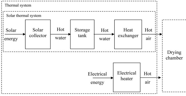
Figure 1. Block diagram of the thermal system.
1) The solar collector;
2) The storage tank;
3) The heat exchanger.
The solar collector is considered to be the main source of the thermal energy or heating in the system. It is used to directly utilize the incident solar energy from the sun and transfers it into the heat transfer fluid, which is chosen to be the water in this work. Also, the storage tank is used, in this work, to store the thermal energy of the water gained in the collector stage. The output water from the tank, which carries certain amount of thermal energy and at specified temperature, enters the heat exchanger stage. This heat exchanger is utilized to transfer a certain amount of the thermal energy of the hot water to the dryer’s inlet air. In this way, the temperature of the dryer’s inlet air can raise to certain temperature. If this temperature is lower than the required drying temperature, then an auxiliary heating source (the electrical heater) will be utilized to supply the deficit in temperature.
3. Control of the Drying Temperature
It is known from the previous discussion that the main function of the electrical heater is to supply the auxiliary heating required by the drying air that supplements the thermal energy deficit of the solar thermal system; to adjust the drying air temperature at the desired optimal value (i.e., 40˚C). Therefore, the suggested block that controls the air drying temperature is shown in Figure 2. Where, in this case, the on/off controller is utilized to provide the electrical heater with the suitable control action. The heater, in turn, can adjust the drying temperature Tdryer to the desired value, by providing additional air temperature  to the available THE. Note that the auxiliary heating, in this case, means that the electrical heater will operate only if the temperature of the output air from the heat exchanger THE is lower than the required value to adjust the drying temperature Tdryer at 40˚C.
3.1. The On/Off Controller
On-off control is perhaps the simplest type of feedback control strategy. The strategy is similar to that of a relay. The following equations define the output of on-off controller [4]:
Output = ON if the controller is in the ON state;
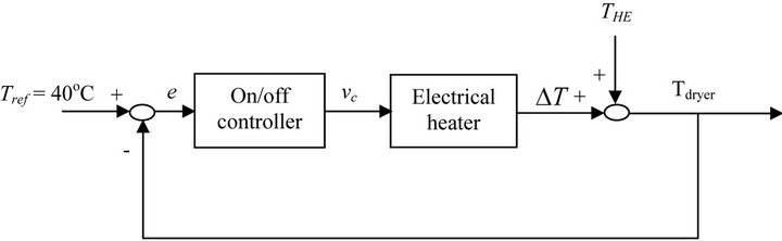
Figure 2. Block diagram of the temperature control system.
Output = OFF if the controller is in the OFF state.
where e is a error and output when ON and output when OFF are values determined based on the application.
When the ON-OFF controller is in the ON state, the controller remains in the ON state until the input to the controller falls below the value of the switch OFF point state until the input exceeds the value of the SWITCH ON point.
The ON-OFF controller is initially in the OFF state. In short, the On-OFF controller output one of two values (“output when ON” or “output when OFF”) based on the value of the input signal.
A system under ON-OFF control will always oscillate. To avoid rapid switching between the ON and OFF states, it is common to introduce a hysteresis (ζ) in the switch. The input-output relation for an ON-OFF controller with hysteresis is shown in below Figure 3.
3.2. The Electrical Heater
The main function of the electrical heater is to make the auxiliary heating of drying air. The auxiliary heating means that the electrical heater will operate only if the temperature of the output air THE from the heat exchanger is lower than the required value to adjust the air drying temperature Tdryer at 40˚C.
If the rated power of the electrical heater [5] is Pheater and the heater efficiency is hheater, then the rate of heat added to the drying air (in the electrical heating chamber) will be
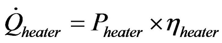 (1)
(1)
Thus, by applying the energy balance principle on the electrical heating chamber will yield [6]
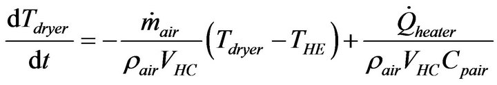 (2)
(2)
where VHC volume of the heating chamber of the electrical heater
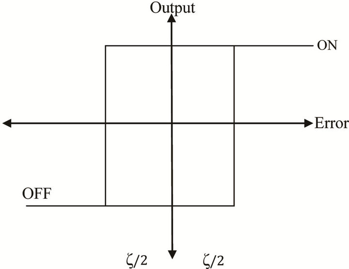
Figure 3. The input-output relation for an ON-OFF controller with hysteresis.
4. Simulation Results of the Thermal System
The complete components of the considered thermal system are simulated in this work by using MATLABSIMU-LINK [7].
The purpose of the temperature control system is to adjust the dryer temperature Tdryer at 40˚C, which is a necessary value for drying the medical herbs. Therefore, to investigate the performance of the proposed temperature control system the response of the drying temperature must be indicated at different cases. Figure 4 illustrates the response of Tdryer in case of using the on/off controller. Where, in this case, the deadband of the controller e is set to be e/2 =1 (since the drying temperature of medical herbs ranges from 35˚C - 45˚C with optimal value 40˚C).
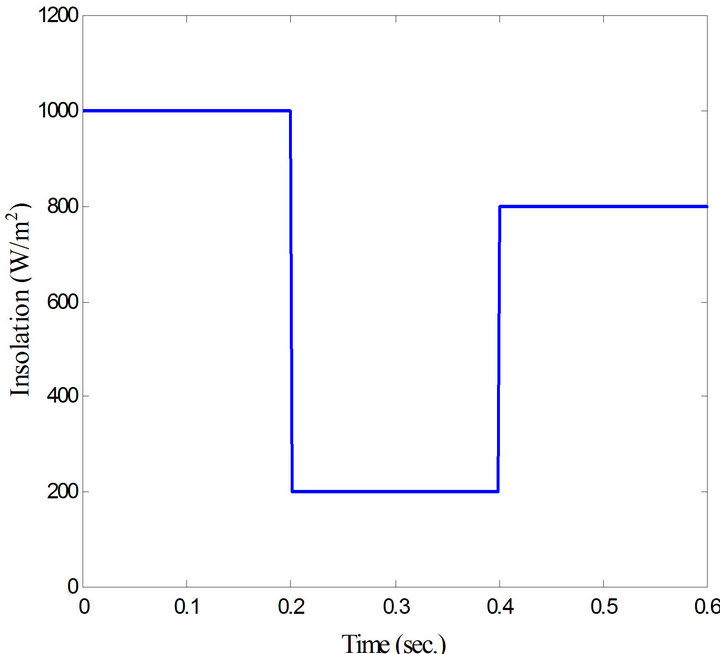
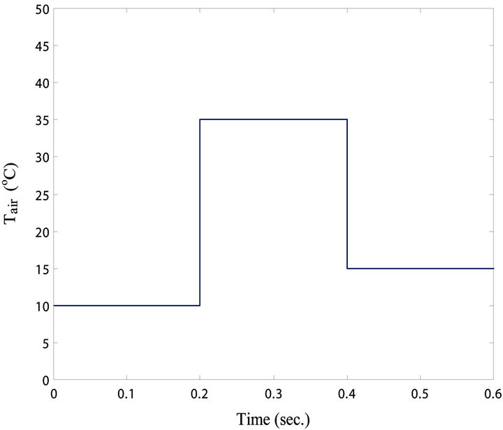
The robustness of the used controller in rejecting the sudden variations in the insolation level or in the ambient temperature is shown in Figures 5 and 6, respectively. Where, Figures 5(a) and (b) illustrate the sudden variation in the insolation level at constant ambient temperature of 23˚C and the corresponding response of Tdryer, respectively. Also, Figures 6(a) and (b) indicate the sudden variation in the ambient temperature at constant insolation of 1000 W/m2 and the corresponding response of Tdryer, respectively. Therefore, the used on/off controller is sufficient for controlling this system and also has a good capability in rejecting the imposed sudden variations in the solar insolation or in the ambient temperature.
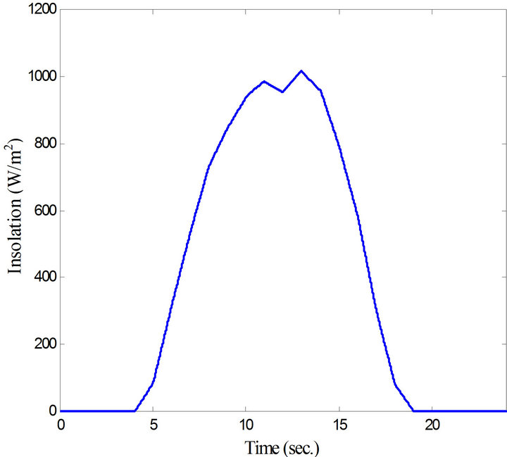
The meteorological data in this work are obtained at two different days with different atmospheric conditions. Figures 7(a) and (b) show the variations of the solar insolation incident on the surface of the solar collector on summer and winter days (in Sinai Peninsula (Abu Rudies) [8,9]), respectively. While, Figure 8 shows variation of the corresponding ambient temperature.
The performance of the solar collector during the sum-
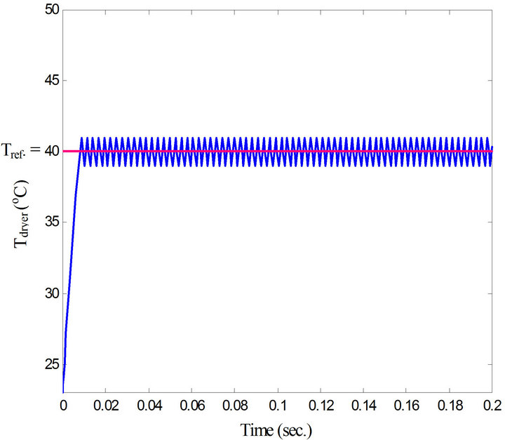
Figure 4. Response of Tdryer with the on/off controller.
 (a)
(a) (b)
(b)
Figure 5. Response of Tdryer with insolation change: (a) Insolation versus time; (b) Tdryer versus time.
mer and winter days is shown in Figures 9 and 10, respectively. Figure 10, as shown, includes the switching control signal of the collector-side path, while Figure 11 shows the temperatures of the water at the inlet and outlet sides of the collector. It is shown from Figures 9 and 10 that the used collector is able to heat the water that flows through it, whenever there is solar illumination; where the heating of the water is proportional to the incident insolation level. Also, it is cleared that the water continues to flow in the collector as long as the temperature of the water at the collector outlet is greater than that at the collector inlet. The initial apparent-rise of the outlet temperature compared with the inlet one, for the two cases, is due to: using the same value of the initial conditions for the two temperatures, the water does not flow in the collector during the night period, and the corresponding variation in the ambient temperature.
Figures 11(a) and (b) show the performance of the storage water tank during the summer and winter days,
 (a)
(a)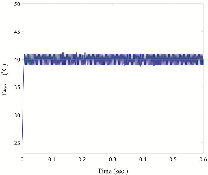 (b)
(b)
Figure 6. Response of Tdryer with ambient temperature change: (a) Ambient temperature versus time; (b) Tdryer versus time.
respectively. Thus, the effect of stratification on the tank is shown in this figure, where the bottom layer exhibits the lowest temperature and the top layer exhibits the highest temperature of all the tank layers. It is indicated that the temperatures of the tank layers increase during the daylight hours and decrease during the night hours, such that the variation of the temperatures is proportional to the variation in the solar insolation.
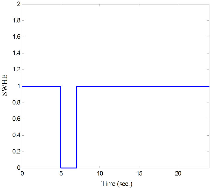
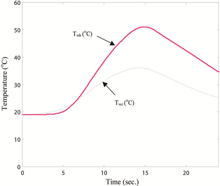
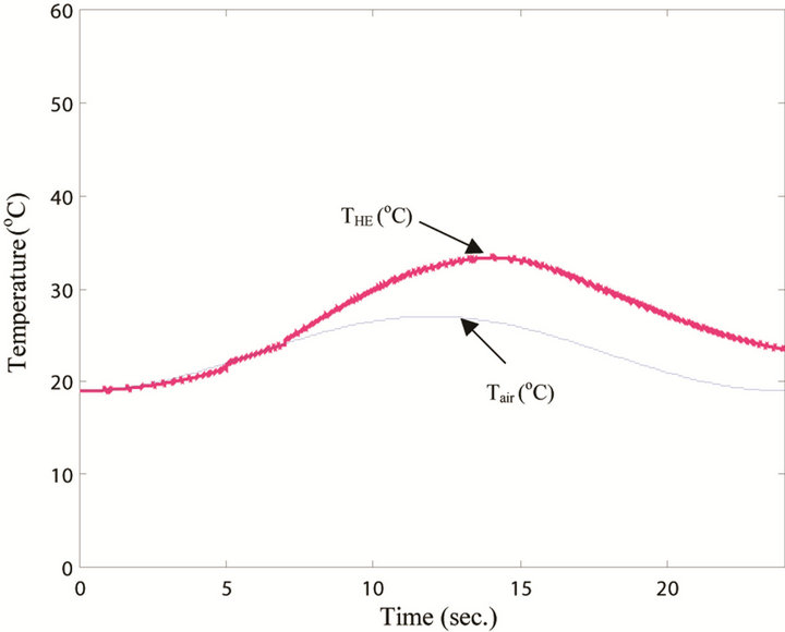
The performance of the heat exchanger during the summer and winter days is shown in Figures 12-15, respectively. Figures 12 and 13 include the switching control signals of the air blower and the heat exchanger side, respectively. While the performance of the inlet and outlet temperatures of the heat exchanger water and the performance of the inlet and outlet temperatures of the heat exchanger air are shown in Figures 14 and 15, respectively.
 (a)
(a)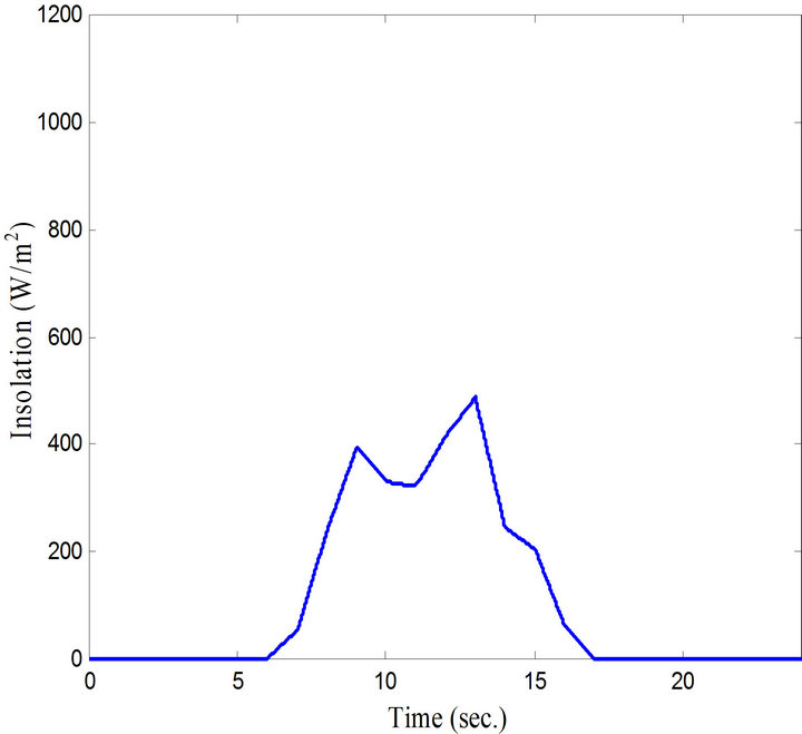 (b)
(b)
Figure 7. Variation of solar insolation: (a) Insolation of the summer day; (b) Insolation of the winter day.
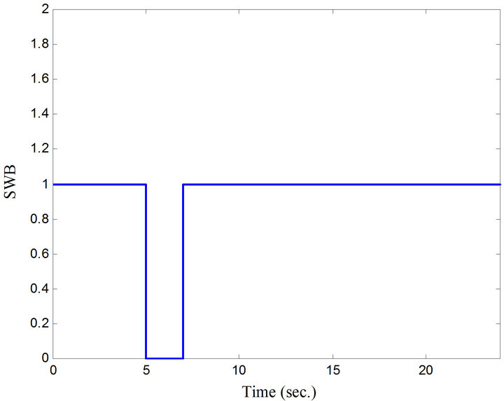
Thus, it is clear from these figures that the switching control signal of the air blower exists as long as there are herbs in the dryer, and that of the heat exchanger side exists as long as the ambient temperature is lower than the desired drying temperature Tref. Also, the inlet temperature of the heat-exchanger water is the temperature of the tank top layer (Figure 11) and the shown difference in temperature between the inlet and the outlet water (which depends on the solar insolation incident on the collector) expresses the rate of the thermal energy transferred to the heat exchanger air. Moreover, the outlet temperature of the heat-exchanger air is increased with respect to the ambient temperature according to the quantity of heat transferred from the water.
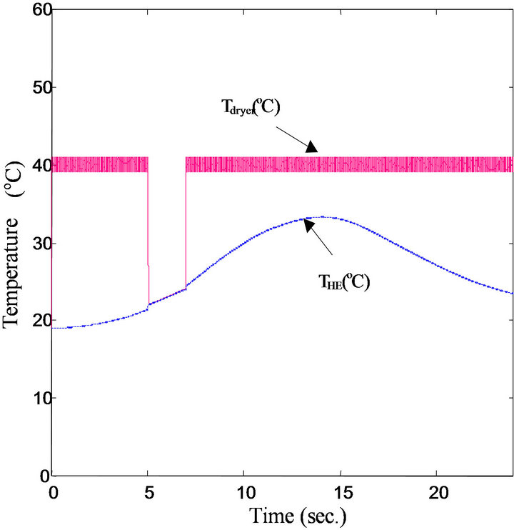
Finally, the performance of the electrical heater is shown in Figures 16 and 17, respectively for the summer
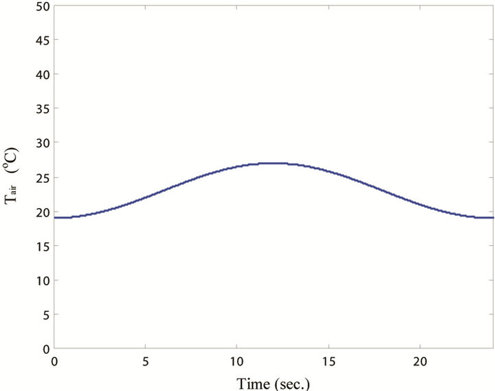
Figure 8. Variation of ambient temperature.
 (a)
(a) (b)
(b)
Figure 9. Switching signal of the collector side: (a) During summer day; (b) During winter day.
 (a)
(a) (b)
(b)
Figure 10. Inlet and outlet temperatures of the collector: (a) During summer day; (b) During winter day.
and winter days. Figure 16 shows the output control signal of the on/off controller, while Figure 17 shows the corresponding air temperature at the inlet and outlet sides of the electrical heater chamber. It is shown from these figures that the electrical heater will be active only if the temperature of the outlet air from the heat exchanger is lower than the desired drying temperature of the medical herbs. Also, these figures and Figure 15 indicate that the temperature of the inlet air to the heating chamber has the same temperature as the outlet air from the heat exchanger, and the temperature of the outlet air from the heating chamber (i.e., the drying temperature) tracks the desired drying temperature.
5. Conclusion
The optimal drying temperature of the medical herbs
 (a)
(a)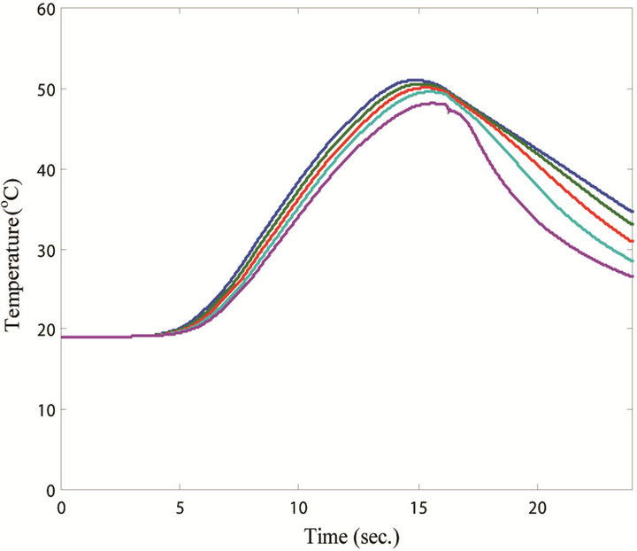 (b)
(b)
Figure 11. Temperature of the tank layers: (a) During summer day; (b) During winter day.
 (a)
(a) (b)
(b)
Figure 12. Switching signal of the air blower: (a) During summer day; (b) During winter day.
 (a)
(a)  (b)
(b)
Figures 13. Switching signal of the heat exchanger side: (a) During summer day; (b) During winter day.
 (a)
(a) (b)
(b)
Figure 14. Inlet and outlet temperature of the heat exchanger water: (a) During summer day; (b) During winter day.
 (a)
(a)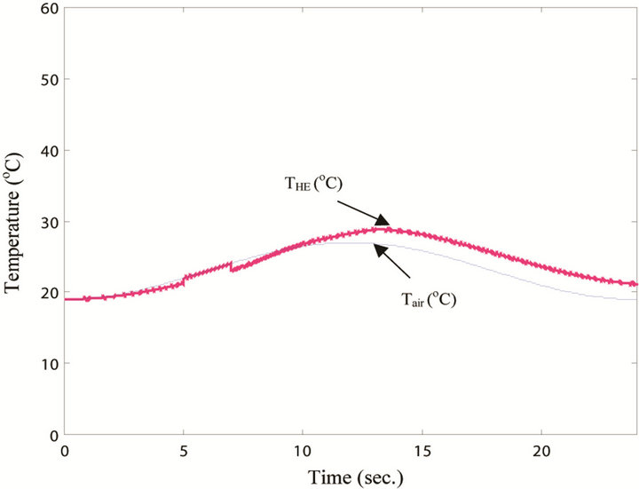 (b)
(b)
Figure 15. Inlet and outlet temperature of the heat exchanger air: (a) During summer day; (b) During winter day.
 (a)
(a)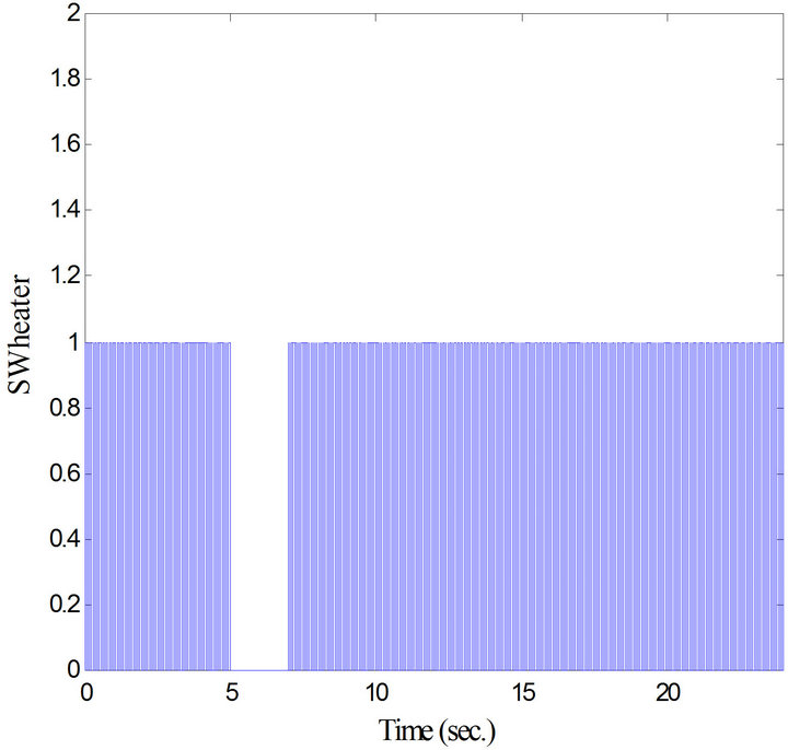 (b)
(b)
Figure 16. Output signal of the on/off controller: (a) During summer day; (b) During winter day.
 (a)
(a) (b)
(b)
Figure 17. Inlet and outlet temperatures of the heating chamber air: (a) During summer day; (b) During winter day.
must be adjusted to about 40˚C. A control technique is proposed to adjust the dryer inlet temperature at the required optimal value. The proposed control technique is based on using the on/off controller, to control the operation of the electric heater whenever necessary. The electric heater will be active only when the temperature of the outlet hot air from the heat exchanger THE is less than 40˚C. The simulation results indicate that the used on/off controller with the tuning of the deadband gives a good capability in rejection, the imposed sudden variations in the solar insolation or in the ambient temperature. Therefore, the developed herb dryer system will be incorrect and continuous operation during the summer/winter day and night hours.
REFERENCES
- G. Grang and H. P. Kumar, “Developments in Solar Drying,” Proceedings of the Second Asian-Oceania Drying Conference (ADC 2001), Pulau Pinang, 2001, pp. 297- 319.
- A. Shafy, F. Famhy and M. Hassan, “Naval Temperature Control Technique for a Medical Herb system Powered by a Photovoltaic Array,” International Journal of Green Energy, Vol. 1, No. 2, 2005, pp. 147-156.
- J. R. Howell, R. B. Bannerot and G. C. Vliet, “SolarThermal Energy Systems: Analysis and Design,” McGrawHill, Inc., New York, 1982.
- T. Markvart, “Solar Electricity,” John Wiley & Sons, Inc., Hoboken, 1994.
- X. Jiang and J. Li, “Design of the Batch Predictive-PID Controller Based on the Nonlinear Electric Heating Model,” Lecture Notes in Electrical Engineering, Vol. 129, No. 6, 2012, pp. 293-298.
- B. Hahn and K. Oldham, “On-Off Iterative Adaptive Controller for Low-Power Micro-Robotic Step Regulation,” Asian Journal of Control, Vol. 14, No. 3, 2012, pp. 624-640. doi:10.1002/asjc.410
- X. Xu, M. M. Meyers, B. G. Sammakia and B. T. Murray, “Thermal Modeling and Life Prediction of Water-Cooled Hybrid Concentrating Photovoltaic/Thermal Collectors,” Journal of Solar Energy Engineering, Transactions of the ASME, Vol. 135, No. 1, 2013.
- Math Works, “Dynamic System Simulation for MatLab,” Software, Version 10, 2010.
- N. Elshahat and A. Zeit, “Aromatic Plants & Its Agricultural-Medical Products,” Arabic, Inc., Egypt, 2003.