Smart Grid and Renewable Energy
Vol.2 No.4(2011), Article ID:8272,8 pages DOI:10.4236/sgre.2011.24038
A Novel Island Detection Methodology for the Realization of Smart Grid
![]()
School of Electrical, Electronic and Computer Engineering, University of Western Australia, Perth, Australia.
Email: {victor.sreeram, herbert.iu}@uwa.edu.au
Received June 21st, 2011; revised July 15th, 2011; accepted September 22nd, 2011.
Keywords: Distributed Generation (DG), Islanding, Non-Detection Zone (NDZ), Circuit Breaker, Contact Parting Time
ABSTRACT
Responding to the problem of increased load demand, progress has been made to develop a new smarter infrastructure, which employs a decentralised approach. This smart decentralised system, termed smart grid, is composed of micro grids which utilise a combination of distributed energy resources (DER). The DERs can either be operated in parallel with the grid or in autonomous condition (intentional-islanding). Operating the DER under intentional islanding condition is seen as the next stage in smart grid’s future development which requires intelligent control implementation. In order to utilise this intelligent control, immediate detection of islanding is essential. This paper proposes a new smarter islanding detection method, which implements the forecast capability of smart grid by detecting the fluctuations before islanding occurs. The proposed method has been tested in simulation and compared against the current islanding detection methods. The simulation results have successfully proven the benefits of the new proposed method over the current methodologies in island detection.
1. Introduction
Currently the area of power generation and distribution is facing some critical issues. Most of them originate from the fact that load demand is increasing around 1.6% every year [1]. One of the major issue concerns about whether the current technology in power generation and distribution, termed grid, is able to cover the future demand with the limited supply. IEA has predicted that the current supply will only be able to cover the increasing load demand for the next 40 years [1]. A further concern is attributed to the efficiency and the environmental impact of the current grid. The current grid is inefficient due to the centralized approach that it employs which results in high power loss in the transmission lines and also reduces the redundancy due to high dependency on the utility. Furthermore, it is not environmentally friendly as most of the centralized power plants are coal powered resulting in an increase in carbon emissions [2]. In an attempt to improve the efficiency, new infrastructure has been developed which follows a decentralized approach towards power generation and distribution. In line with the support of a rapid growth in renewable energy development and investment [3], smart grid has been introduced as the new decentralized structure utilizes distributed energy resources (DER) for power generation.
DER is a small scale generating resource that is located close to the load or distributed system [4] and is generally operated in parallel with the grid. A DER consists of two parts; 1) energy generation (called distributed generation or DG), 2) energy storage system (ESS) [5]. DER offers many benefits such as reduced power loss in transmission line and increase in power reliability and quality [6]. Despite the benefits, the integration of DER faces some issues, among them is islanding.
Islanding is generally defined as a situation where the power from utility is off, but one (or more) sections of the system still continues to have power flow through it as it still being energized by DG. This sectionalized area is called an island. Unintentional islanding refers to a formation of island due to faults on the utility side that result in the opening of the circuit breaker in the upper stream of the grid [7]. There are few drawbacks associated with unintentional islanding which includes line worker safety issues, difficulty in maintaining the voltage and current to meet the load demand, and any hazards associated with out-of-phase reclosing [4].
Considering these drawbacks, IEEE 1547-2003 standard recommends to detect and cease the operation of the DER or DG within 2 seconds [8]. However, continuing the DER under intentional islanding operation will improve the system’s reliability and thus is under consideration for future development of smart grid. Researchers in [9-11] are promoting intentional islanding operation and have provided control mechanisms to maintain the system’s stability during islanding and to synchronize the phase of the DG to the grid before auto-reclosing happens.
Islanding should be detected immediately for the better control of the power system and also to avoid the above mentioned hazard. This paper proposes a new islanding detection method that provides a better islanding detection time in comparison with the existing methods. By utilizing the delay introduced in the circuit breaker, the new method is adding a forecasting capability to the smart grid. The aim of the proposed method is to overcome the drawbacks introduced in the current methodologies in detecting islanding and improve the performance of the system when fault happens.
The paper is organised into seven different sections. Section 2 provides an overview of the current methodologies of island detection. Section 3 introduced the new proposed method to detect islanding. Section 4 provides a general idea of the delay introduced in circuit breaker as to understand the principle use in the proposed method. Section 5 presents a control algorithm in response to the new method. Section 6 provides simulations cases and results as to assess the performance of the new method. Finally the conclusion is provided in Section 7.
2. Overview of Islanding Detection
The current islanding detection methodologies can be divided into remote and local methods. Remote method is implemented at the utility side while local method is implemented at the DG side. The local method is further classified into active, passive, and hybrids as shown in Figure 1.
Remote method depends on the communication between utility and DG to detect islanding [4]. An example of remote method is power line carrier communication. It works by continuously sending signal from the transmitter located on the utility side to the receiver on the DG side [12]. Islanding is detected when the disconnection of
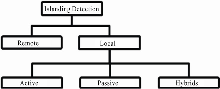
Figure 1. Islanding detection methodologies [4].
the grid interrupts this communication. One other example is signal by disconnect, which is the opposite of the power line communication technique. It monitors the circuit breaker state and sends a signal to the DG through other transmission lines when the circuit breaker trips [12]. Remote method provides better reliability in islanding detection than local methods but it is more expensive to implement.
Local method detects islanding by taking measurement of the voltage or frequency or current at the Point of Common Coupling (PCC) between the DG and the load [4]. As already mentioned before, local method can be categorised as active, passive, and hybrid. Passive method detects islanding by observing the system’s characteristics and compares them with islanding condition characteristics. One known passive technique is OVP/ UVP or OFP/UFP (Over/Under Voltage/Frequency Protection) which monitors the voltage or frequency and detects islanding when the voltage or frequency goes out of range [12]. This method immediately introduces the existence of non-detection zone (NDZ) as shown in Figure 2. Non-detection zone, as defined in [13], is the difference between active and reactive power on the island when islanding cannot be detected by the corresponding method. In comparison to other local methods, passive method has the largest NDZ due to its incapability to detect islanding when the power consumed by the load is equal to the power generated by the DG [4].
Solving the passive method’s drawback, active technique introduces a disturbance signal to be injected to the system and observes the reactions or changes. It then compares it with islanding condition characteristics. The effect of the disturbance signal is negligible when the utility is connected to the system but it becomes apparent when the island is created. An example of active technique is Sandia Voltage Shift (SVS) [12]. SVS controls
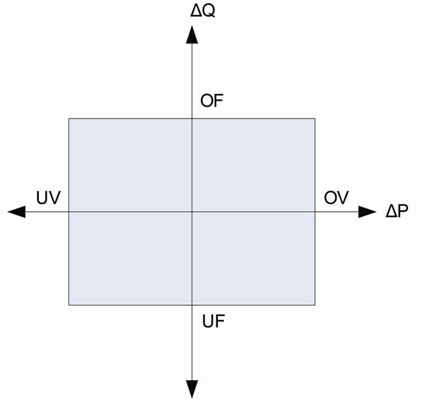
Figure 2. NDZ of OVP/UVP—OFP/UFP [12].
the output current of the inverter to fluctuate in the same manner as the utility voltage and uses it as the disturbance signal to be injected to the system [14]. When the utility is connected, the fluctuation in the grid voltage is small and so thus the injected current, hence the effect is negligible. After the disconnection of the main utility grid, if fault happens there will be huge fluctuations in voltage and current in the micro grid section, which in turn affects the PCC voltage to go out of the OVP/UVP range.
While active method has been successful in reducing the NDZ of the passive method by introducing disturbance to the system, the introduced disturbance also deteriorates the system’s power quality. In an attempt to minimise this drawback, hybrid method employs both active and passive methods but only utilise active method after the passive method signals the probability of islanding condition [4]. As a result of utilising both active and passive methods, hybrid method has the longest islanding detection time.
3. Introduction to the New Method
From section II, it can be seen that the currently utilised detection methodologies detect islanding after an island has been created. It is monitoring the fluctuations in the voltage, current or frequency at PCC as a result of the grid disconnection or circuit breaker opening due to fault. The new proposed idea is to detect islanding before an island is created or before the circuit breaker tripping. Hence, the measurement point should be moved from PCC to the utility side of the circuit breaker as shown in Figure 3. The proposed method is detecting the irregularities in the grid’s voltage or current or frequency that will open the circuit breaker and takes control of the system before the grid gets disconnected.
By merely changing the measurement point, the proposed method overcomes the drawbacks introduced in local methods. Firstly, as the main focus is to detect the fault signal and not measuring the active and reactive power of island, it eliminates the existence of NDZ in-
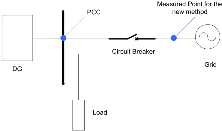
Figure 3. Measure points of current methods and new method.
troduced in passive methods. Secondly, as NDZ is eliminated, it also eliminates the needs to inject disturbance to the system. Lastly, the islanding detection time is not affected by the time delay introduced by the circuit breaker as islanding is detected before the disconnection of the grid. The circuit’s breaker delay will further be discussed in section IV. Hence, the new method offers faster islanding detection time than the current methodologies. Figure 4 below illustrates the time taken to detect islanding for each method from the time fault occurs.
4. Circuit Breaker Delay
Circuit breaker is a switching mechanism that is part of circuit protection system, which is responsible for interrupting the current’s flow when fault is detected [15]. It does not interrupt the flow as soon as fault is detected. It is waiting for an “open signal” from a relay instead. Relay is another circuit protection subsystem that is responsible for detecting the fault and sending an “open signal” to the circuit breaker [15]. The time taken from the initiation of fault until an open signal is sent by the relay is called the trip delay (Tdelay). Other than trip delay, there are others delay associated in circuit breaker operation as shown in Figure 5.
Existing methods will start operating when circuit breaker opens or parts. Hence, the circuit breaker delay
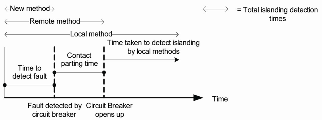
Figure 4. Timing sequence in islanding detection.
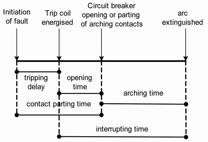
Figure 5. Timing sequence in circuit breaker operation [16].
that affects the new method is the contact parting time. From Figure 5, it is shown that contact parting time is the sum of trip delay and opening time of the circuit breaker. It is the time taken from the initiation of fault (detected by relay) until the circuit breaker opens up. The tripping delay can be varied while the opening time is fixed depending on the mechanical structure of the circuit breaker. The variation of the tripping delay is depended upon its fault current. As the fault current increases, the tripping delay decreases. This is called the inverse-time setting [15]. Fault is detected if the current (I) or voltage (V) is greater than the rated current (also called pickup current, Ipickup) or voltage (Vrated) of the circuit breaker. Relay will send an open signal to the circuit breaker if during this tripping delay, the current still remains above the rated current (I > Ipickup), otherwise no signal is sent to the circuit breaker. The main purpose of the tripping delay is that the circuit breaker will not trip during the high inrush current when the system just starts up [16]. If the fault current is greater than ten or twenty times the pickup current (I >> Ipickup), the relay will go to instantaneous setting. Instantaneous means there is no intentional delay added to the system, it is only the relay operating time. According to [17], the relay response is about 0.5 to 1 cycle. Any intentional delay is added in order to decrease the interrupting time of the circuit breaker and thus increase the lifetime of the circuit breaker as given in [18].
5. Proposed Control Mechanism
While it is necessary to provide tripping delay in protection operation, it also provides a drawback. The overload current that is being passed for short duration could damage other circuit devices or sensitive load attached to it. The existing solution as provided in [16] is to match the overload characteristics with all of the attached components. This solution does not solve the problem entirely. For example, given that all of the components of the circuit match circuit breaker characteristics rated current of 50 A (Ipickup = 50 A). From [16], it is known that the circuit breaker will let 135% overload current (Ioverload = 1.35 Ipickup) to pass for 1 hour before the circuit breaker trips. During this time period of 1 hour, the overload current can potentially heavily damage the devices connected to the grid. The proposed detection method can lessen the damage by requesting the circuit breaker to open before the current tripping delay is passed. Thus for that purpose, a control mechanism for the new detection method is developed.
The control algorithm ignores fault due to high inrush current and starts to take over as soon as the second fault is detected. If control has started or stabilised and the fault current still exist within the allowable tripping delay, then an open signal to the circuit breaker is sent immediately. If the fault doesn’t exist anymore after the control stabilised, then turn off the control. Hence, not only it offers faster detection times but also protection. There are four cases that need to be considered in developing the control mechanism. 1) To avoid nuisance tripping, inrush current due to the starting of a system should be ignored by the control system, as it is not a fault and the circuit breaker used is chosen to tolerate this current. Hence, circuit breaker will not open up even though the current is greater than the pickup current (I > Ipickup).
2) The case where fault only exist for a short period of time (transient fault) and already ceased before the tripping delay of the circuit breaker is reached. In this case, the proposed control would have already taken over as the pickup current is already over the limit (I > Ipickup). However, in order to increase efficiency, the control system should stop operating when it knows the fault already ceased before the tripping delay is reached.
3) The case where the control already starts operating and the fault still exist, but the circuit breaker has not opened up. In this case, a signal to open circuit breaker immediately is sent. In this way, the new method, not only it offers faster detection times but also protection.
4) The case where the control already starts operating and the circuit breaker already opens up. This case is the normal case where the method will have detection time advantage in comparison with other islanding detection methodology. Figure 6 below provides the flowchart of the proposed control algorithm where Tstart-up is the initialization time of the system, T is the total time and T1 is the time when the fault is detected.
6. Simulations
Figure 7 shows the main circuit topology use in the simulation to test the proposed method performance and Figure 8 shows the Matlab implementation of the topology. Inverter in the simulation model represents an ESS of the DER and voltage source represents the voltage
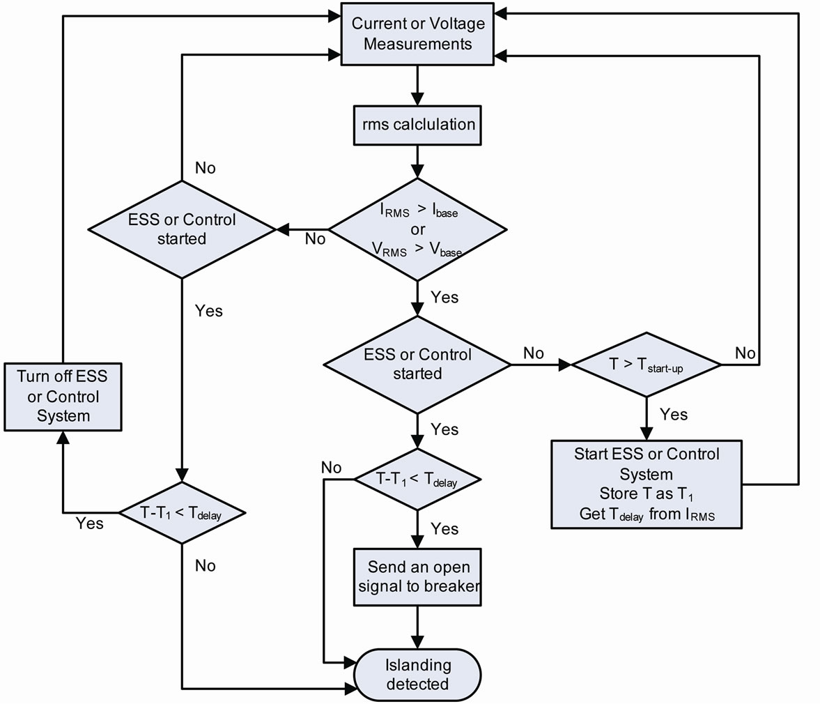
Figure 6. Proposed control algorithm.

Figure 7. Simulation model in single-phase.
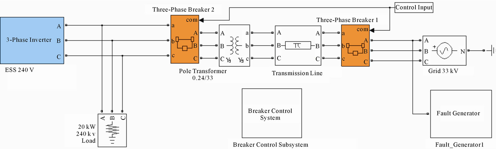
Figure 8. Three-phase model implementation.
coming from the micro grid. The proposed method performance is compared with the widely used passive detection method, OVP/UVP and remote method (signal by disconnect). The model depicted in Figure 8 is simulated under intentional islanding condition where the ESS under the new proposed method acts as an uninterruptible power supply (UPS) when islanding detected. At the beginning of the simulation the inverter is not energized and upon energization is operated in a voltage-controlled mode when started. The moment the inverter starts indicates the time the control starts to take over. Proposed method will start to take control as soon as fault current is detected on the utility side of the grid, remote method starts when the circuit breaker trips and passive method will detect islanding as soon as the PCC voltage is not in the range of 0.88 pu to 1.1 pu as stated in the IEEE Std. 929-2000 [19].
As the proposed method takes advantage of the delay introduced in the circuit breaker, thus to simulate the worst case scenario, the circuit breaker tripping delay is set to be minimum which is its instantaneous setting. Hence, the tripping delay of the circuit breaker is set to be 10 ms or ½ cycles. For simplicity, the load power factor is kept at 1 and thus only resistive load is used. Other parameters that are configured in the simulation are shown in the Table 1.
In order to test the new method, it is necessary to generate a fault that will open the circuit breaker. Therefore, two types of single-phase fault are created as shown in Figure 7. The purpose of both faults is to create a surge current “Is” whose RMS value is greater than the circuit breaker rating. Fault generator 1 realises this by conducting a voltage swell in the system while fault generator 2 is performing a current swell in the system. As depicted in the Figure 9, the generated fault is high enough to open circuit breaker as the increase in current is more than 100% of the circuit breaker rated current and stays for more than 1 cycle. This will set circuit breaker to run in instantaneous setting. As shown in Figure 9, local
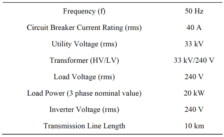
Table 1. Parameter set-up.
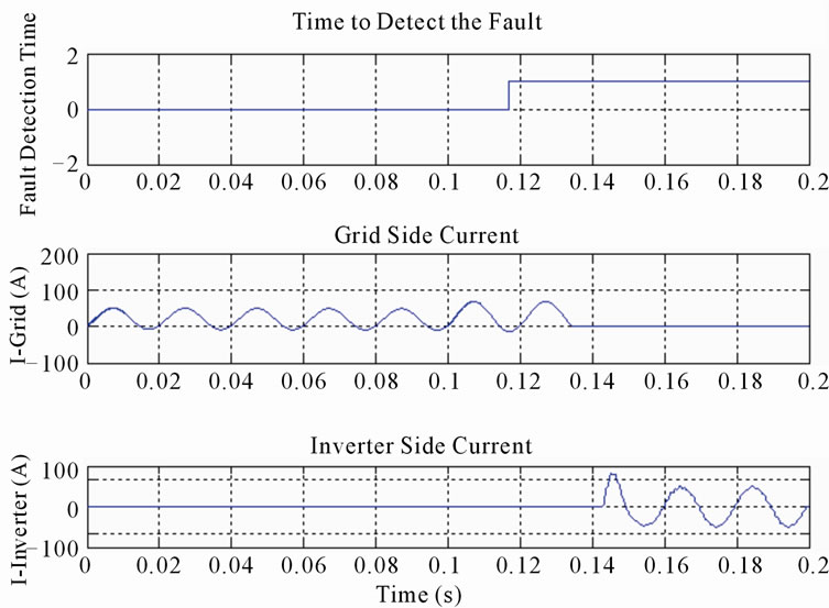
Figure 9. The time the fault is detected, circuit breaker opens up, and inverter starts in OVP/UVP method.
method will only detect fault when the circuit breaker opens and the current on the inverter or load side begins to drop which in turn will switch on the ESS for supply.
Fault generator 2 is used in the simulation which produces the current fault and is started at 0.1 s and runs until 0.15 s. The circuit breaker detects the fault at 0.1162 secs and will open up after about 10 ms delay. Hence, base on the analysis in section III, inverter should start at 0.1162 sec in the proposed method, 0.1262 s in the remote method, and greater than 0.1262 s in the passive method. This timing difference is verified in the Figure 9. Figure 9 shows that the inverter starts at about 0.1432 secs in the OVP/UVP method. This timing difference will affect the system’s stability and performance as has been depicted in Figures 10, 11, and 12.
The load voltage and load current resulting from employing the proposed method are depicted in Figure 10. Because in the proposed method the ESS begins to produce power when the grid is still connected so to avoid out of phase closing of the ESS with the grid, a phase lock loop (PLL) is employed in the simulation which is also shown in the single line diagram depicted by Figure 7. Figure 10 depicts that the ESS system (inverter) when operated with the proposed control methodology shows a smooth transaction from the grid connected mode to the islanding mode none or with negligible transients. The current of the inverter will follow the voltage waveform, as it has linear relationship with voltage (Ohms Law).
Looking at the simulation results of Figure 11, it can be seen that the remote method experiences a little instability at the point where the grid is disconnected by the circuit breaker. Overall the settling time of the remote islanding detection method is good as compared to the OVP/UVP method. In the case of passive method, the inverter does not start immediately after the fault occurs as remote does. Thus, it more disturbance as it provides a lo-
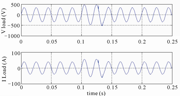
Figure 10. PCC voltage and current for the new method.
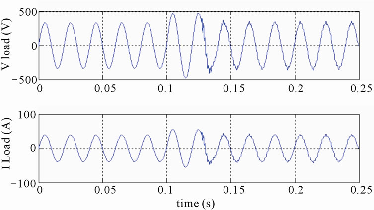
Figure 11. PCC voltage and current for remote method.
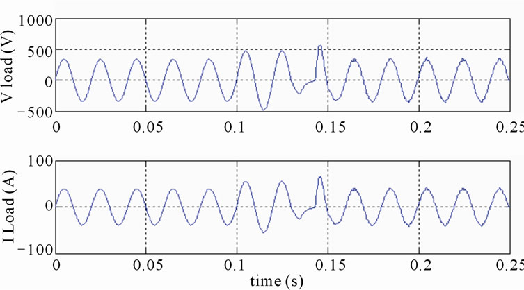
Figure 12. PCC voltage and current for ovp/uvp method.
nger period where there is no power being supplied by the ESS after islanding. Moreover in the passive method when the ESS is started the voltage and current both peak reaching a 1.66 pu value. In reality, this disturbance can potentially damage the load and the inverter itself.
Furthermore in the passive method there are some times when the voltage and current of the load is zero. This is the time when the grid is already disconnected and the inverter has not started yet as it has not been triggered by the OVP/UVP method. In this time, the load will experience a black out for a short time, which leaves the ESS fails to act as a perfect UPS. The proposed method improves ESS performance as a perfect UPS by starting before the grid is disconnected and thus eliminating the blackout zone. Another advantage of the proposed method is to prevent a blackout caused by melting of the fuse on the spur lines. According to [20], in most grid configuration the primary feeder is protected by a circuit breaker or automatic circuit recloser while the spur line is often protected by the fuse. The coordination between the automatic circuit recloser and the fuse is managed in a way where the fuse will clear the faulted section. But using this approach has an disadvantage, the transient faults will blow the fuse causing an interruption to the downstream users. Using the proposed method the utility company can replace the fuse with the circuit breaker or the circuit breaker can be put in series with the fuse, thus opening the breaker instantly thus providing financial savings to the utility company from blown up fuses.
7. Conclusions
This paper presents a new islanding detection method with a proper control algorithm to work along with the new method. The proposed method is intended to operate under intentional islanding condition as intentional islanding operation is seen as the future of smart grid. The simulation results provided in this paper have successfully proven that the new method provides better islanding detection time and performance in comparison with the existing methods. The new method achieves this by utilizing the delay introduced in circuit breaker. The delay introduced in circuit breaker is depended mostly on its fault current in comparison with the circuit breaker ratings. The advantages of the proposed method over the existing ones are 1) Elimination of non detectable zones that are a major drawback of the passive method. 2) The proposed method can be more cost effective then the remote method of power line communications as it involves lesser components then the remote method. 3) The proposed method can be used to prevent a blackout in the spur lines when coordinated properly with the fuse. 4) The early start of the ESS in case of the proposed method has many advantage of improved stability. Moreover if the ESS is a spinning reserve (synchronous or induction generator) the early start of ESS is more advantageous as the dynamics of the machinery takes time to settle. 5) Unlike the active and the hybrid methods the proposed method doesn’t inject any perturbations into the systems thus improving the stability and the power quality of the overall system. 6) Moreover according to the control algorithm developed for the proposed method, the controller will open the circuit breaker immediately if the fault still exists when the ESS is started/stabilized. Whereas in the existing islanding detection methodology, the existing control paradigms will allow the overload current to pass through for a considerable amount of time thus damaging the system. 7) Because of the intentional islanding operation in case of the overload current fault, the proposed method creates a functional requirement that leverages the interconnection of DG sources thus promoting smart grid structure. Implementation of this method could integrate smart grid’s capability and performance in island detection.
8. Future Work
The simulation results provided in the paper has shown the general performance of the proposed method in comparison with the existing method. Further simulation will focus on connecting a DG to the micro grid system to compare the performance of the proposed method with the existing methods in the presence of matched power generated by the DG and power consumed by the load. In addition to that, by connecting the DG in parallel with the ESS, ESS performance in each method as a power system stabilizer can further be measured.
9. Acknowledgements
The authors would like to thank Dr. Shagufta Murad, Dr. Javaria Murad and Mrs. Dujung Soejati Bachtiar for their support during the documentation of this paper.
REFERENCES
- IEA, “World Energy Outlook 2008,” 2008. http://www.iea.org/textbase/nppdf/free/2008/weo2008.
- Litos Strategic Communication, “The Smart Grid: An Introduction,” 2010. http://www.oe.energy.gov/DocumentsandMedia/DOE_SG_Book_Single_Pages.pdf.
- REN21, “Renewables Global Status Report: Energy Transformation Continues Despite Economic Slowdown,” 2010. http://www.ren21.net/globalstatusreport/g2009.asp.
- P. Mahat, Z. Chen and B. B. Jensen, “Review of Islanding Detection Methods for Distributed Generation” Electric Utility Deregulation and Restructuring and Power Technologies, 3rd International Conference, Nanjing, 2008, pp. 2743-2748.
- B. L. Capehart, “Distributed Energy Resources (DER),” 2010. http://www.wbdg.org/resources/der.php.
- G. Pepermansa, J. Driesenb, D. Haeseldonckxc, R. Belmansc and W. D’haeseleerc, “Distributed Generation: Definition, Benefits and Issues,” Energy Policy, Vol. 33, No. 6, 2005, pp. 787-798. doi:10.1016/j.enpol.2003.10.004
- R. A. Walling and N. W. Miller, “Distributed Generation Islanding—Implications on Power System Dynamic Performance,” Power Engineering Society Summer Meeting, Chicago, Vol. 1, 2002, pp. 92-96.
- IEEE Std. 1547-2003, “IEEE Standard for Interconnecting Distributed Resources with Electric Power Systems,” 2003, pp. 10-11.
- H. Zeineldin, E. F. El-Saadany and M. M. A Salama, “Intentional Islanding of Distributed Generation,” Power Engineering Society General Meeting, San Francisco, Vol. 2, 2005, pp. 1496-1502.
- I. J. Balaguer, U. Supatti, Qin Lei, Nam-Sup Choi and F. Z. Peng, “Intelligent Control for Intentional Islanding Operation of Microgrids,” International Conference: Sustainable Energy Technologies, Singapore, 2008, pp. 898- 903.
- S. Conti, A. M. Greco, N. Messina and U. Vagliasindi, “Generators Control Systems in Intentionally Islanded MV Microgrids” International Symposium: Power Electronics, Electrical Drives, Automation and Motion, Ischia, 2008, pp. 399-405.
- D. Velasco, et al., “Review of Anti-Islanding Techniques in Distributed Generators,” Renewable and Sustainable Energy Review, Vol. 14, No. 6, 2010, pp. 1608-1614. doi:10.1016/j.rser.2010.02.011
- H. H. Zeineldin and J. L. Kirtley, “Islanding Operation of Inverter Based Distributed Generation with Static Load Models,” Power and Energy Society General Meeting Conversion and Delivery of Electrical Energy in the 21st Century, Pittsburgh, 2008, pp. 1-6.
- J. Stevens, R. Bonn, J. Ginn and S. Gonzales, “Development and Testing of an Approach to Anti-Islanding in Utility-Interconnected Photovoltaic Systems,” 2010. http://photovoltaics.sandia.gov/docs/PDF/0800steve.pdf.
- R. C. Dorf, “The Electrical and Engineering Hand Book,” CRC Press, Boca Raton, 1993.
- J. C. Whitaker, “AC Power Systems Handbook,” 3rd Edition, CRC Press, Boca Raton, 2007.
- R. Natarajan, “Power System Capacitors,” CRC Press, Boca Raton, 2005. doi:10.1201/9781420027204
- J. C. Das, “Reducing Interrupting Duties of High-Voltage Circuit Breakers by Increasing Contact Parting Time,” IEEE Transactions on Industry Applications, Vol. 44, No. 4, 2008, pp. 1027-1033. doi:10.1109/TIA.2008.926235
- IEEE Std.929-2000, “IEEE Recommended Practise for Utility Interface for Photovoltaic (PV) System,” 2000, pp. 5-6.
- KAON Electric, “KAON FuseSaver,” 2011. http://kaonelectric.com/uploads/Files/KAON_FuseSaver_Brochure_-_low_res.pdf