Smart Grid and Renewable Energy
Vol.2 No.1(2011), Article ID:4036,10 pages DOI:10.4236/sgre.2011.21004
Switched Reluctance Generator for Variable Speed Wind Energy Applications
![]()
School of Engineering and Advanced Technology, Massey University, Palmerston North, New Zealand.
Email: {a.arifin, i.h.albahadly}@massey.ac.nz
Received October 29th, 2010; revised November 16th, 2010; accepted November 20th, 2010.
Keywords: Switched Reluctance Generator (SRG), Wind Energy, Variable Speed Drives
ABSTRACT
The aim of this paper is to analyze the potential of switched reluctance generator (SRG) in wind energy application. The machine comprises of switched reluctance generator, power converter and controller. In this paper the main elements that form the generator system is discussed. It also highlights the common type of converter and structure used for SRG in wind energy application and types of control strategy available. Using power converter for switching the generator can operate over a wide speed range. Its applications in high speed area such as starter/generator for aircraft and gas turbine has been established, however the low/medium speed operation is still at an early stage of research. In order to subject the machine to various parameters, offline modeling is being investigated to produce the best optimum design.
1. Introduction
Wind is a natural source of energy related to the low and medium speed range. In order to extract energy from the wind, machine that can be controlled to generate at variable speed are preferred/of advantage to ensure optimum performance. Among the common types of machines used for wind energy are: double fed induction generator (DFIG), induction generator and also synchronous generator. The potential candidate to the group is the Switched Reluctance Generator (SRG) which comprises of SR generator, power converter and controller as shown in Figure 1.
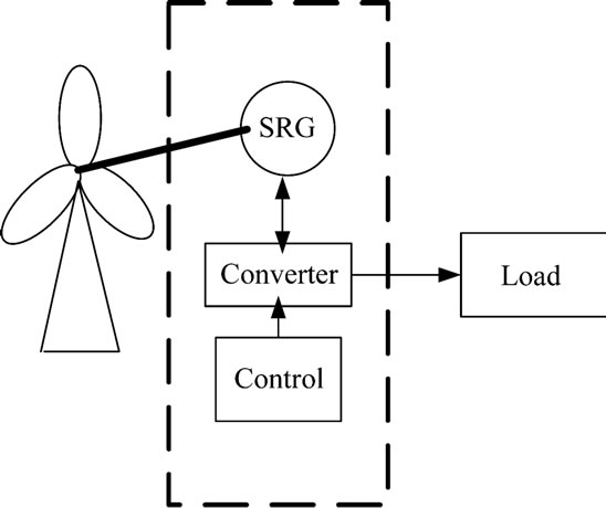
Figure 1. Main components of SRG.
SRG has attracted researches to investigate the potential of the machine mainly due to its attractive characteristics over conventional machine as stated below:
• Simplified construction with rotor only consists of laminated steel
• Concentrated phase winding is only on the stator poles
• Absence of permanent magnet which gives low manufacturing cost.
• Has higher reliability since each phase is electrically and magnetically independent
• Low inertia since it does not have windings or magnets on the rotor hence machine can operate at low wind speed [1]. It also allows rapid response to load variation due to this low inertia [2].
• Requires power converter circuit which controls the instant of energizing and de-energizing to match its speed and load.
Extensive ongoing research has been done on the low and medium speed range which studies the suitability of using SRG in wind energy applications. The objective of generator control in wind energy application is to optimize the energy captured to produce maximum output power. Speed control strategy has been used in [3,4] which requires a good design of the controller to control the output power. The authors in [5] compared two control strategies and states that PWM control with fixed firing angles has higher efficiency as compared to fixing the turn off angle whilst varying the turn on angle. The latter strategy has been proposed in [1] which regulates turn on angle based on fuzzy logic algorithm which shows that efficiency increases with increase in rotor speed. The common features between the control methods according to research papers above are the use of single pulse mode operation. This is due to the excitation of generating mode which is prior to the alignment of poles where inductance is maximum. The control of current during low value of back EMF which for motoring uses Pulse Width Modulation Control (PWM) is currently under investigation for generator [6-8]. Feedback of back EMF, increase of voltage need to be put in place to boost the phase current of SRG before chopping of current could be performed.
From literature review above the research on SRG focus on the control strategy. Few papers has discussed on its structure [9-11] and power converter [12-16].
The research on SRG in wind energy application is still ongoing and further research on the machine is required before it can be commercially available.
2. Switched Reluctance Generator (SRG)
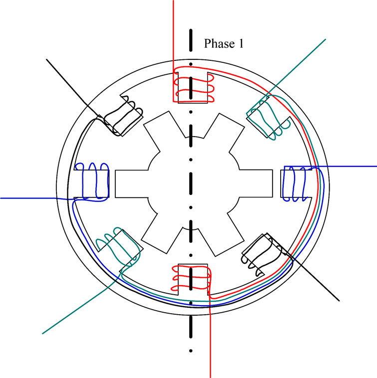
The operation of the machine as a generator is by controlling the switching sequence of the power converter during the decreasing inductance profile. It is referred to as a doubly salient pole due to the salient pole of its stator and rotor structure. Salient pole refers to the structure of the element protruding from the yoke into the air gap. Rotor and stator are made of steel laminations and only the stator poles has windings concentrated around it [1]. This leaves the rotor free from windings, magnets and brushes. The windings of one stator pole are connected in series with the opposite stator to form one phase. The windings can be arranged in such a way that more than 2 opposite stator poles can form one phase. Typical configuration of the machine includes 3 phase 6 stator or 4 rotor (6/4) or 12/8 and 4 phase 8/6 or 16/12. Figure 2(a) is showing an example of the 4 phase SRG with 8/6 poles configuration while Figure 2(b) is showing a 3 phase generator with 12/8 poles configuration.
The operation of switched reluctance machine as motor has made a good progress however its operation in generating mode is slowly evolving.
3. SRG Operating Principles
The operation of SRG depends entirely on synchronized excitation of the set of stator windings to create continuous rotation of rotor. The movement of rotor with respect to excited stator phase varies the inductance of the machine periodically from maximum to minimum hence
 (a)
(a)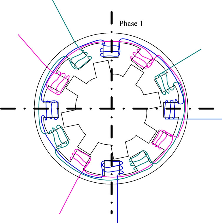 (b)
(b)
Figure 2. Configuration of switched reluctance generator: (a) 4 phase 8/6 and (b) 3 phase 12/8.
torque and power is produced. During the aligned position of rotor and stator, inductance is maximum and minimum during the non-aligned position [17].
The operation of Switched Reluctance Generator (SRG) is similar to Switched Reluctance Motor (SRM). However, for SRG the excitation of stator phase must be made when rotor is moving pass the stator when inductance is decreasing as shown in Figure 3(a)(ii) and 3(b) whereas for motoring the excitation is on the increasing
 (a)
(a)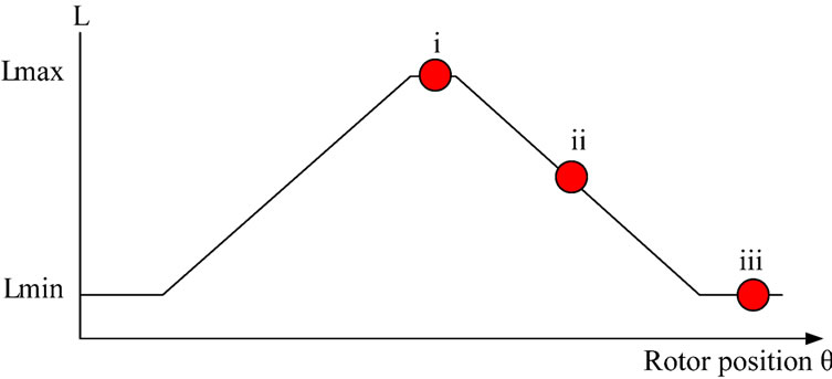 (b)
(b)
Figure 3. Variation of inductance with respect to movement of rotor. (a) Rotor movement with respect to stator; i) Maximum inductance, minimum reluctance (full alignment); ii) Inductance decreasing linearly; iii) Minimum inductance (mis-alignment); (b) Complete inductance profile with respect to rotor position.
inductance region. Movement of rotor in an out of alignment with the stator poles creates variation of reluctance flux path. It can be seen that this variation creates conversion of energy. Hence in every cycle the flux must be established and returned to zero before excitation of the next phase.
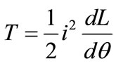
The torque (T) is produced by the tendency of the rotor moving to the excited stator phase winding where minimum reluctance occurs independent of direction of current (i) flow as shown by equation below:
 (1)
(1)
Where (L) is the phase inductance and (θ) is the rotor position.
The phase of the stator must be excited in synchronism with rotor position to produce continuous torque. If the phase is excited when the poles are unaligned as in Figure 3(a)(iii), no torque will be produced since  is zero. However, if the stator phase is excited as rotor is moving pass the stator pole as in Figure 3(a)(ii) there will be a braking torque trying to realign the poles back together creating negative torque extracting energy from prime mover during generating mode. A controller with position feedback must be developed so that pulses of phase current can be synchronized according to the appropriate rotor position.
4. SRG Equivalent Circuit
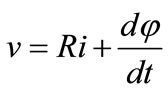
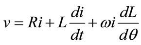
The voltage equation for one phase winding takes into account the following assumptions; mutual coupling between phases is almost zero, no fringing effect of flux around pole corners and all flux between poles crosses the air gap in radial direction is as follows:
 (2)
(2)
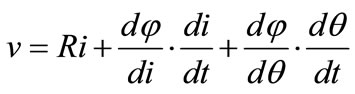
Flux,  is a function of phase current
  and rotor position
 , hence
  can further be extended as follows
 (3)
(3)
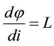
Also
 (4)
(4)
Differentiate Equation (4) as a function of current
 (5)
(5)
Since 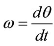 Equation (3) can be written as
 (6)
(6)
where  is the terminal voltage,
  is the phase current,
  is the flux linkage (volt.sec),
  is the phase resistance,
  phase inductance,
  indicates the rotor position and
  is the angular velocity of the rotor (rad/s).
The last parameter on the right hand side is the back EMF of the machine and it appears during separation of poles and with increase in speed. From the back EMF equation it can be seen that  represents the slope of the inductance profile as shown in Figure 3(b). For motoring mode, the operation is during the increasing region hence
  is positive. As for generating mode the operation is during the decreasing inductance region hence
  is negative, which implies that the back EMF aids the increase of current during generating mode as shown in the equivalent circuit of one phase of SRG in Figure 4. The amplitude of phase current (iphase) depends on back
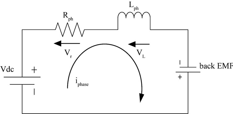
Figure 4. Equivalent circuit for one phase of SRG (without power electronic devices).
EMF which varies with speed ( ). Vr is the voltage across the phase resistance (Rph) and VL is the voltage across the phase inductance (Lph).
Furthermore it can be seen that as rotor pole moves out of alignment with the stator pole, it gains speed during decreasing inductance slope. Hence, after both switches are turned off, current will be large with the aid of back EMF. Phase current will eventually subside as back EMF opposes the negative voltage and  becomes zero.
During motoring mode, when the rotor moves into alignment with the stator pole, speed increases and the inductance increases as well. The back EMF that results from the change of inductance together with saturation effects aids the voltage in reducing the phase current. As compared to motoring mode the control of firing angles during generating mode is more complicated due to this back EMF effect [18].
5. Power Converter Circuit for SRG
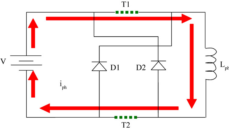
The most common converter circuit for SRG is the Asymmetric Half Bridge Converter (AHBC). It consists of two switching devices and two power diodes per phase. Figure 5 shows the typical self excited AHBC circuit for SRG during excitation and generation. There are several other types of circuits that use lesser components as compared to AHBC such as:
• C-dump power converter
• R-dump converter
• Bifilar type converter
• Split DC converter
Some converter circuits are only suitable for even number of phases due to arrangements of capacitor and switches that require balance of power [19] since the supply voltage needs to be halved during excitation and de-fluxing. The bifilar type converter requires good connectivity between phase winding. It has the ability to regenerate the stored magnetic energy to the bifilar winding however perfect coupling of magnetic circuit is difficult to achieve causing losses in the circuit.
Due to the advantages that AHBC offers in line with the requirement makes it a popular choice. It has the ability to shape the phase current using 3 switching sequence such as positive voltage, zero voltage and negative voltage. This form of switching is suitable during low and medium speed where soft switching is required under the current chopping mode. It is also able to operate at higher speed during single pulse mode where the switches are closed for excitation and open for de-fluxing namely known as hard switching [20]. Its usage in high speed applications such as aircraft starter/generator and also in low and medium speed application proves its wide operating range. It has also been a popular choice for wind energy applications. For the above reasons the AHBC is chosen for this first stage of study.
When switches are closed as in Figure 5(a), current builds up and energy is stored as magnetic field. There will be a slow increase in current since excitation start during high inductance region. When switches are open as in Figure 5(b) direction of current in winding remains the same but its direction in terminal voltage causes voltage to be negative. This in turn returns the current to zero. Current waveform during excitation and generation of the circuit in Figure 5(a) and (b) is as shown in Figure 6.
 (a)
(a)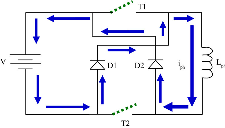 (b)
(b)
Figure 5. Typical self excited AHBC circuit operation during (a) excitation and (b) generation.
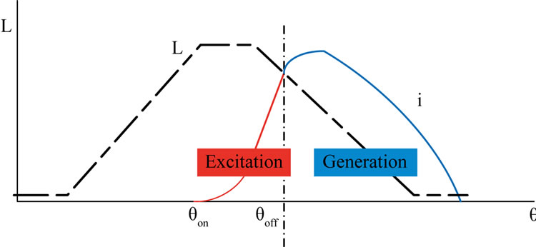
Figure 6. Current waveform during generator operation.
6. Control Methods for SRG
The heart of the SRG depends on its control strategy which is through proper switching of power electronic devices as shown in Figure 7. Careful placement of the firing angles must be made to ensure continuous operation of the generator as well as maximizing its efficiency. Is has been mentioned in [21] that by increasing the excitation current, output power will increase as compared to increasing speed. Also the firing angles determine the area of flux linkage which corresponds to energy converted per stroke. Current research shows that the output power and voltage depend on angular speed and excitation voltage. By adjusting the excitation voltage the output power can be controlled [22]. This shows the importance of firing angles on output power. Due to its inherent characteristics such as nonlinearity its optimal control is difficult to achieve. The main reason is because there are various combinations of firing angles that would produce the same amount of output power [23]. This implies that its efficiency, torque ripple and dc link current are also different according to the various angle combinations. Hence as stated earlier most of the ongoing research on control of SRG is on ways to determine the optimal firing angles to achieve maximum efficiency.
As observed, in generating mode single pulse operation is common for both low and high speed. The difference lies in the control strategies applied. Unlike in motoring single pulse mode is used for high speed whereas pulse width modulation for low speed.
SRG control strategy based on the determination of the firing angles could be classified into three groups. These groups are:
• fixing both the turn on and turn off angles
• one of the angles may be fixed whilst varying the other
• vary both turn on and turn off angles
As there will be variation in wind velocity, the best strategy is to vary both the turn on and turn off angles in order to achieve optimum performance. There are few studies which highlight the strategy for varying both the firing angles such as: flux linkage [24], mapping [25] and
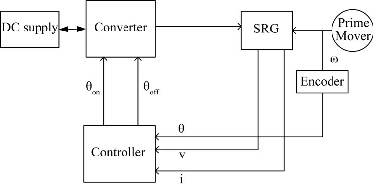
Figure 7. Basic control model for SRG.
also curve fitting [18].
Apart from the firing angles, the SRG structure also plays a role in terms of efficiency. Higher number of poles is suggested in [22] for wind energy applications. The common types of poles configuration used are the 8/6 or 12/8.
Various methods has been used to maximize the energy captured during low/medium speed such as: speed feedback control, using area of magnetization curve by controlling reference current, closed loop output power control.
7. Simulation Model of SRG
Output power of SRG depend on various variables such as: excitation current, excitation voltage, rotor position and also rotor speed. The parameters above can be controlled to achieve high efficiency of the SRG. However the challenge lies on how to determine the best parameters that will produce the optimum performance. Based on that, the modeling of the SRG is proposed using MATLAB/SIMULINK. The software has all the tools to model the dynamics of electrical machines. The simulations are performed using block diagrams and special MATLAB functions.
At this stage of research a simulation model of the SRG comprising of the converter, controller and generator operating at steady state is proposed. Assuming that there is no mutual interaction between phases and neglecting flux linkage the representation of SRG is performed for one phase. Electromagnetic characteristics and torque can be calculated individually for each phase hence additional phases can be added. At a later stage the model will then be subject to testing with a prototype for practical implementation.
The SRG is modeled as an inductor and a resistor in series as shown in Figure 4. The phase of SRG is modeled according to Equation (2) in Simulink. The model is composed by several modules such as position sensor, power converter, controller, and phase winding. Each module has been developed and tested by parts and integrated to form one complete system as shown in Figure 8.
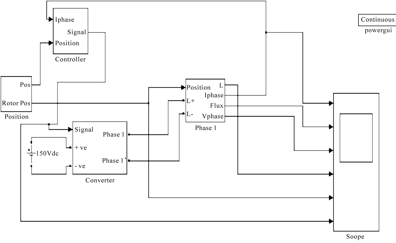
Figure 8. Basic model of SRG using MATLAB/SIMULINK.
The details of the subsystems are as follows:
The position sensor as shown in Figure 9 imitates the prime mover. The speed of the rotor is integrated to obtain the mechanical position.
The converter used is the standard Asymmetric Half Bridge Converter (AHBC) as shown in Figure 10 which consists of IGBTs and power diodes. The function of the converter is to excite the phase winding of the SR generator. The switching signal to the gate of the IGBT is received from the controller.
The controller function which ensures commutation of power switches at turn on and turn off angles is performed by the switch function seen in Figure 11.
The phase winding constructed using mathematical functions as in Equation (2) is shown in Figure 12. The Power System Blockset (PSB) module is linked with SIMULINK module using the source to signal blocks: voltage block and controlled current source block.
8. Simulation Results
The SRG used for simulation is based on parameters from a 3 phase 6/4 machine. The maximum and minimum phase inductances are 60mH and 8mH. Currently the simulation is tested by fixing both the firing angles with constant speed.
It can be seen in Figure 13 that the single pulse current increases slowly during the increasing inductance region and as switches are turned off the current gradually decreases and reduced to zero. The waveform produced by simulation is similar to waveform shown in Figure 6. While Figure 14 shows the simulation results in chopping mode operation. According to simulation, the firing angles must vary to accommodate the change in speed.
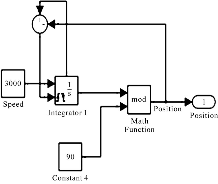
Figure 9. Details of position sensor.
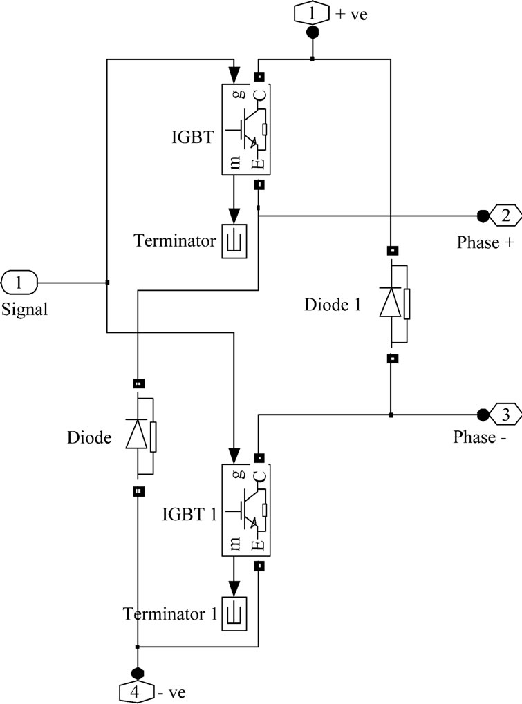
Figure 10. Asymmetric Half Bridge converter.
Overall from the simulations performed, it can be seen that the amount of power generation depends on placement of firing angles. A good control strategy which synchronizes the phase current with rotor position would provide more efficient SRG system. If we advanced turn on angle it gives ample time for current to build up. However the disadvantage of advancing too far is that it will be in the positive torque region which reduces the efficiency. The firing angles must vary to accommodate changes in speed to maximize the output power. The simulation model needs to be enhanced to cater for variation in the above parameters.

Figure 11. Details of controller.
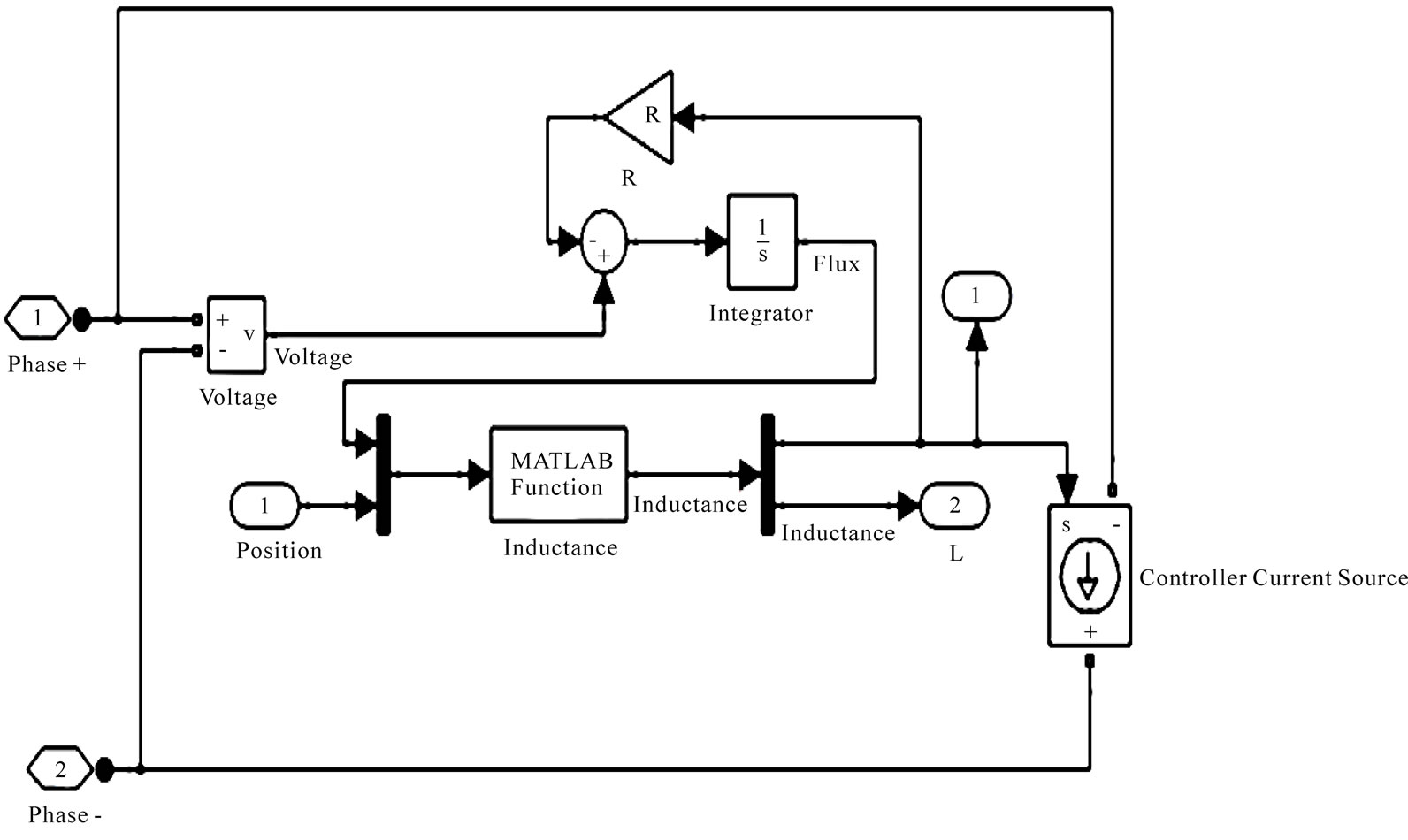
Figure 12. Details for one phase winding.
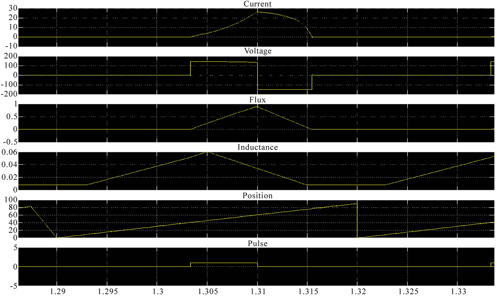
Figure 13. Steady state model results of single pulse phase current, excitation voltage, flux, inductance profile, rotor position and firing pulse of SRG at fixed firing angles with constant speed.
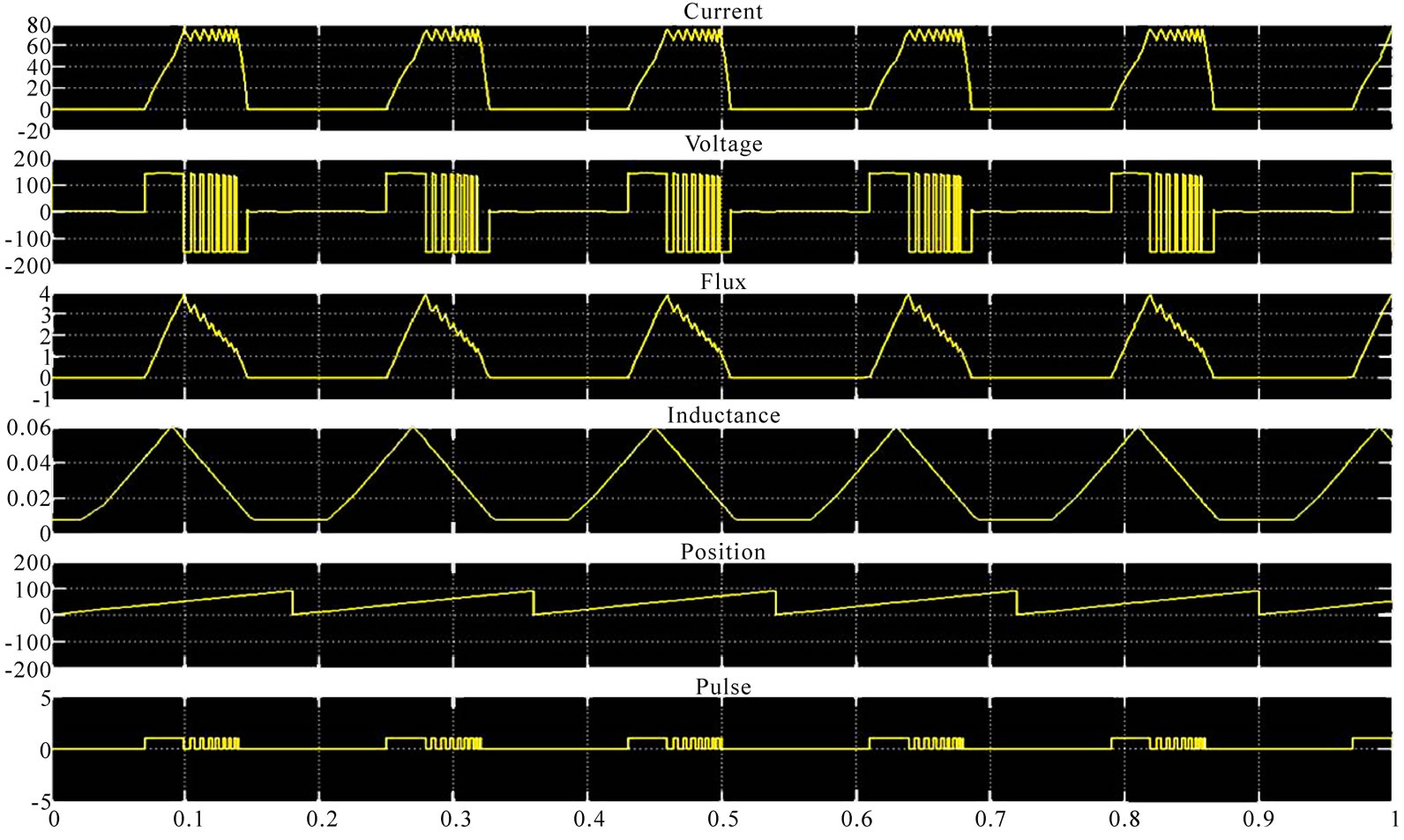
Figure 14. Steady state model results of chopping phase current, excitation voltage, flux, inductance profile, rotor position and firing pulse of SRG at fixed firing angles with constant speed.
9. Conclusions
The paper made an attempt to view the potential of the SRG in wind energy application. Its operation, converter and also its control strategies have been discussed. Based on literature review SRG has the potential to be used in wind energy application due to its simple structure, ability to operate at low speed due to low inertia of the machine, ease of maintenance and advantage in control strategy. The use of power converter for switching allows it to operate at variable speed operation. By proper placement/excitation of firing angles the output power can be maximized. Future work will look into enhancing the model to cater for various parameters such as the control methods in order to vary the firing angles, varying speed and also include load. The final model will allow user to study the characteristic of the machine and choose the optimum design based on its parameters.
REFERENCES
- H. Chen, “Implementation of a Three-Phase Switched Reluctance Generator System for Wind Power Applications,” 14th Symposium on Electromagnetic Launch Technology, Victoria, 2008, pp. 1-6. doi:10.1109/ELT.2008.104
- E. Darie and C. Cepisca, “The Use of Switched Reluctance Generator in Wind Energy Applications,” 13th Power Electronics and Motion Control Conference, Poznan, 2008, pp. 1963-1966. doi:10.1109/EPEPEMC.2008.4635553
- R. Cardenas, W. F. Ray and G. M. Asher, “Switched re-Luctance Generators for Wind Energy Applications,” 26th Annual IEEE Power Electronics Specialists Conference, Atlanta, 1995, pp. 559-564.
- Q. Zhang, X. Wang, X. Zhu and D. Liu, “A Small Single-Phase Switched Reluctance Generator for Wind Power Generation,” Proceedings of the 5th International Conference on Electrical Machines and Systems, Shenyang, 2001, pp. 1003-1006.
- C. Hao, M. Chao and Z. Xucheng, “Research on the Switched Reluctance Wind Generator System,” 2001 IEEE International Conference on Systems, Man, and Cybernetics, Tucson, Vol. 3, 2001, pp. 1936-1941.
- R. Cardenas, R. Pena, M. Perez, J. Clare, G. Asher and P. Wheeler, “Control of a Switched Reluctance Generator for Variable-Speed Wind Energy Applications,” IEEE transactions on Energy conversion, Vol. 20, No. 4, December 2005, pp. 781-791.
- P. Chancharoensook and M. F. Rahman, “Control of a Four-Phase Switched Reluctance Generator: Experimental Investigations,” IEEE International Electric Machines and Drives Conference, Madison, Vol. 2, 2003, pp. 842- 848.
- E. Echenique, J. Dixon, R. Cardenas and R. Pena, “Sensorless Control for a Switched Reluctance Wind Generator, Based on Current Slopes and Neural Networks,” IEEE Transactions on Industrial Electronics, Vol. 56, No. 3, March 2009, pp. 817-825. doi:10.1109/TIE.2008.2005940
- H. C. Lovatt and J. M. Stephenson, “Influence of Number of Poles per Phase in Switched Reluctance Motors,” IEE Proceedings-B Electric Power Applications, Vol. 139, No. 4, July 1992, pp. 307-314. doi:10.1049/ip-b.1992.0037
- M. A. Mueller, “Design of Low Speed Switched Reluctance Machines for Wind Energy Converters,” 9th International Conference on Electrical Machines and Drives, Canterbury, 1999, pp. 60-64. doi:10.1049/cp:19990991
- M. A. Mueller, “Design and Performance of a 20 kW, 100 rpm, Switched Reluctance Generator for a Direct Drive Wind Energy Converter,” IEEE International Conference on Electric Machines and Drives, San Antonio, 2005, pp. 56-63. doi:10.1109/IEMDC.2005.195701
- A. Fleury, D. Andrade, E. S. L. Oliveira, G. A. FleuryNeto, T. F. Oliveira, R. J. Dias and A. W. F. V. Silveira, “Study on an Alternative Converter Performance for Switched Reluctance Generator,” Industrial Electronics, 2008. IE-CON 2008. 34th Annual Conference of IEEE, Orlando, 2008, pp. 1409-1414.
- W. S. Heglund and S. R. Jones, “Performance of a New Commutation Approach for Switched Reluctance Generators,” Proceedings of the 32nd Intersociety Energy Conversion Engineering Conference, Honolulu, 1997, pp. 574-579.
- M. Lipták, V. Hrabovcová, P. Rafajdus and B. Zigmund, “Switched Reluctance Machine with Asymmetric Power Converter in Generating Mode,” Acta Electrotechnica et Informatica, Vol. 7, No. 1, 2007, pp. 5-10.
- N. K. Singh, J. E. Fletcher, S. J. Finney, D. M. Grant and B. W. Williams, “Evaluation of Sparse PWM Converter for Switched Reluctance Generator,” International Conference on Power Electronics and Drives Systems (PEDS), Kuala Lumpur, 2005, pp. 721-725.
- A. Takahashi, H. Goto, K. Nakamura, T. Watanabe and O. Ichinokura, “Characteristics of 8/6 Switched Reluctance Generator Excited by Suppression Resistor Converter,” IEEE Transactions on Magnetics, Vol. 42, No. 10, 2006, pp. 3458-3460. doi:10.1109/TMAG.2006.880388
- K. Ogawa, N. Yamamura and M. Ishda, “Study for Small Size Wind Power Generating System Using Switched Reluctance Generator,” IEEE International Conference on Industrial Technology, Mumbai, 15-17 December 2006, pp. 1510-1515. doi:10.1109/ICIT.2006.372468
- Y. Sozer and D. A. Torrey, “Closed Loop Control of Excitation Parameters for High Speed Switched-Reluctance Generators,” IEEE Transactions on Power Electronics, Vol. 19, No. 2, March 2004, pp. 355-362. doi:10.1109/TPEL.2003.823178
- C. Pollock and B. W. Williams, “Power Convertor Circuits for Switched Reluctance Motors with the Minimum Number of Switches,” Electric Power Applications, IEE Proceedings B [see also IEE Proceedings-Electric Power Applications], Vol. 137, No. 6, 1990, pp. 373-384. doi:10.1049/ip-b.1990.0046
- E. Elwakil and M. Darwish, “Critical Review of Converter Topologies for Switched Reluctance Motor Drives,” International Review of Electrical Engineering, Vol. 2, No. 1, January-February 2007, pp. 50-58.
- M. Nassereddine, J. Rizk and M. Nagrial, “Study on Excitation Control of Switched Reluctance Generator for Wind Energy Conversion,” Australasian Universities Power Engineering Conference (AUPEC), Sydney, 2008, pp. 1-5.
- A. Fleury, D. Andrade, A. W. F. V. Silveira, F. S. L. Ribeiro, A. Coelho and L. G. Cabral, “Dependence of the Switched Reluctance Generator Output on the Speed and the Excitation Voltage,” 34th Annual Conference of IEEE Industrial Electronics (IECON), Orlando, 2008, pp. 1101- 1105.
- D. A. Torrey, “Switched Reluctance Generators and Their Control,” IEEE Transactions on Industrial Electronics, Vol. 49, No. 1, 2002, pp. 3-14. doi:10.1109/41.982243
- C. Mademlis and I. Kioskeridis, “Optimizing Performance in Current-Controlled Switched Reluctance Generators,” IEEE Transactions on Energy conversion, Vol. 20, No. 3, September 2005, pp. 556-565. doi:10.1109/TEC.2005.852960
- E. Mese, Y. Sozer, J. M. Kokernak and D. A. Torrey, “Optimal Excitation of a High Speed Switched Reluctance Generator,” Fifteenth Annual IEEE Applied Power Electronics Conference and Exposition (APEC), 2000, pp. 362-368. doi:10.1109/APEC.2000.826128