Smart Grid and Renewable Energy
Vol.1 No.1(2010), Article ID:1944,8 pages DOI:10.4236/sgre.2010.11004
Modeling of Work of Filling Granular Filter with Active Cooling
![]()
Institute of Computational Technologies of Siberina Branch of Russian Academy of Sciences, Novosibirsk, Russia.
Email: rych@ict.nsc.ru
Received November 24th, 2009; revised May 10th, 2010; accepted May 12th, 2010.
Keywords: Mathematical Modeling, Granular Filters, Heat-and-Mass Transfer
ABSTRACT
The solid propellant gas generators having high gas capacity are widely used for fast pressurization of elastic shells of saving devices of different applications. A typical example of such devices are safety system of automobile (airbags). After collision of an automobile with an obstacle the combustion products of gas generator fill the shell during 60 – 100 milliseconds. However the temperature of combustion products even of “low-temperature” fuel compositions of gas generators appears not below 1500К and to reduce of its it is necessary to apply a various types of porous and filling granular filters. There are passive and active granular filters. The passive filter can cool of combustion products as a result of absorption of heat only. The active cooling is evaporation of the granule material and in this case takes a place more intensive cooling of combustion products in the filter. The numerical modeling of cooling process of hightemperature combustion products at their movement in bulk of granular filter of active cooling is investigated. As the material of granules was used the carbonate of magnesium. At its heating takes a place process of gasification and formation of a porous slag shell which sublimates at higher temperature. The physical model of such spherical granule can be presented as the central part consisting of the carbonate magnesium surrounded with the porous slag spherical shell through which gaseous products of gasification of the central part are filtered. The problem of distribution of heat in each granule is Stefan problem when at the given temperature on the surface of sphere there is the front of gasification moving inside of the bulk of material. It is assumed that combustion products are the perfect gas moving in the filter. The upwind difference scheme of the second order of the accuracy with TVD properties was applied to calculation of the movement of gas. The results of calculations at various values of key parameters of the active and passive filters allow to draw a conclusion about enough high efficiency of active cooling filters.
1. Introduction
The gas generators with a solid-fuel propellant, which possess a high gas output, have gained a widespread acceptance in the devices for a rapid supercharge of elastic shells applied in various life saving devices. The devices for car safety (air bags) are the typical examples of such devices, in which the supercharge of safety cushions protecting the driver and the passengers from traumas in accident situations must occur during 60-100 milliseconds. The temperature of combustion products of even “lowtemperature” fuel compositions of such gas generators, however, proves to be above 1500 К, and to reduce it to acceptable values, which do not burn through the material of walls of elastic inflated shells, one uses various porous and filling granular filters. The filling granular filters with a granulated material of the so-called active cooling are sufficiently promising for such purposes. In such filters, the material of granules may decompose at their heating thereby contributing to a more intense cooling of the combustion products both at the expense of heat absorption at the evaporation of granules and at the expense of mixing of low-temperature gaseous products of the decomposition of granules with high-temperature combustion products of the gas generator. At present, the computations of the performance of such filters are carried out within the framework of engineering approaches based on the use of balance relations closed by various empirical dependencies.
2. Physical and Mathematical Models of the Filter Functioning
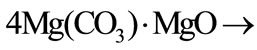
The magnesium carbonate was considered as the material of granules. A simplified kinetic scheme of such a granule was accepted as a model of the granule destruction. The magnesium carbonate gasification with the formation of porous shells was assumed to occur at the granule heating, and this process occurred during two stages. The water steam is at first released, and the first slug shell forms according to the scheme: 
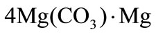 then, at a higher temperature, this slug shell decomposes in its turn into a solid residual (the second slug shell) and the carbonic acid:
 .
.
The following basic assumptions were made at the modeling of processes in the cooling chamber with a pouring active filter:
• The filter represents a porous medium consisting of spherical granules of the same size;
• The gasification of the granule at its heating is governed by a model of the compressing kernel with a solid porous frame. The carbon dioxide and the water steam are the gaseous gasification products;
• The combustion products of a solid-fuel propellant of the gas generator are represented by a chemically non-reactive perfect gas consisting of the mixture of the carbon dioxide (the mass fraction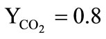 ) and the water vapors (the mass fraction
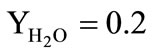 );
);
• The gaseous medium in the cooling chamber consists of a mixture of the carbon dioxide, water steam, and air, which fills the chamber at the initial moment of time. The gaseous mixture motion is unsteady, axisymmetric, and is governed by the system of the Navier-Stokes equations;
• The filter granules are at rest, the exchanges of the momentum and energy between the gas and granules as well as the mass supply from the granules due to their gasification are considered;
• The alteration of the gaseous phase composition at the expense of a diffusion and transfer of non-reacting mixture components is taken into account.
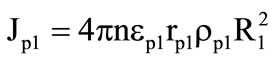
2.1 Mathematical Model of the Granule Destruction
The physical model of a spherical granule of the filter may be presented in the form of a sphere with the central kernel (Figure 1) consisting of the magnesium carbonate, which is surrounded by two porous slug shells (1,2), through which the gaseous decomposition products are filtered. The entire granule in its initial state is a kernel. In the process of its heating, one can identify three main stages. The first stage starts from the granule heating at the expense of heat exchange with the carrying gas until the temperature on its surface reaches the first temperature of gasification . After that, the second stage starts-the formation of the first slug shell (1) and the
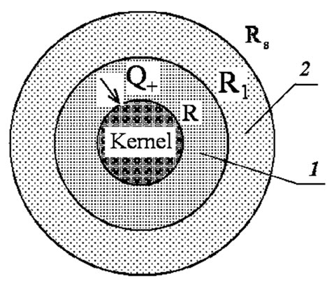
Figure 1. Scheme of the granule gasification.
gasification front motion towards the sphere center, if the heat flux  to the boundary of the granule kernel
  exceeds its outflow
  inside the kernel. The velocity of the gasification front motion is determined from the condition
 , where
 are the phase transition heat and the kernel material density, respectively. When the temperature on the granule surface
  reaches the second gasification temperature
  (
( ) the slug shell material also starts to be gasified. A new gasification front
  arises, which also moves to the sphere center and forms the second slug shell (2). The motion velocity of the second gasification front is determined similarly:
 , where
  are the heat fluxes to the gasification front and from it as well as the phase transition heat and the density of the material of the first slug shell. This is the third stage of the process. The radius of the external shell
  remains constant. When describing the gasification process the following main assumptions were made:
1) The difference of the actual granule shape (for example, the cylinder) from the spherical shape is taken into account by introducing an equivalent sphere diameter , where
  is the granule volume.
2) The gaseous decomposition products are in a thermal equilibrium with slug frames. There are no chemical reactions and heat sources.
3) The gas pressure in porous medium is constant and is equal to the ambient pressure.
4) The porous shells are handled as a continuum with unified thermophysical characteristics inside it, which are averaged for the gaseous and solid phases.
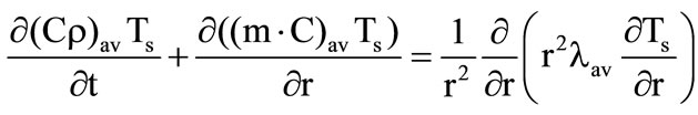
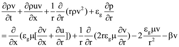
The problem is considered in the one-dimensional unsteady formulation, the heat equation is written in the spherical coordinate system separately for the kernel and porous shells:
a) The granule kernel 
 (1)
(1)
b) The spherical layers of porous shells

 , (2)
, (2)
where the second item on the left-hand side accounts for the heat transfer inside the shell at the expense of gaseous gasification products,  for the first shell and
  for the second shell,
  are the mass fractions of gaseous products at the gasification of shells.
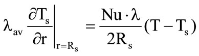
The description of the above three process stages reduces to the formulation of various boundary conditions for equations (1) and (2). At the first stage ( , equation (1) is solved under the following boundary conditions:
 ;
; , where
  is the gaseous phase temperature near the granule surface;
  are the thermal conductivity coefficient of gas and the Nusselt number, respectively. The problem is solved until the condition
 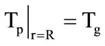 is satisfied. At the second stage, Equations (1) and (2) are solved jointly under the following boundary conditions:
 ;
;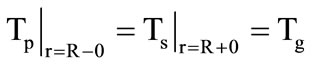 . (3)
. (3)
The velocity of the motion of the front of the kernel gasification is determined from the condition
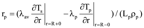 . (4)
. (4)
The new position of the gasification front boundary is found from the solution of equation . The boundary condition at
  are specified depending on whether there is here a gasification of the shell material (the third stage) or there is no gasification. If
 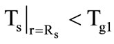 (no gasification), then the following condition is specified:
 , (5)
, (5)
otherwise the condition 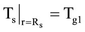 is specified. If there is gasification here (the third stage) the motion velocity of the new gasification front is determined from a condition similar to (4), but with its values of thermophysical parameters. According to the accepted model of compressing kernel, the granule radius
  is set constant, and the heatexchange condition (5) is again specified on the granule surface.
The averaged thermophysical parameters of porous shells were determined as follows:
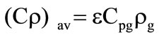 ;
;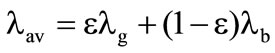 , where
  is the mass fraction of gaseous products at the gasification of corresponding shells. Gas parameters in porous shells:
 ;
; ;
; ;
;  is the motion velocity of the gasification front of the corresponding shell and its thermophysical parameters; p is the pressure in gaseous phase near the granule surface. The dynamic viscosity coefficient was determined by the Sutherland formula:
 . A correction to the Nusselt number, which is related to the presence of a transverse blowing through the surface of the porous shell at its gasification was taken into account within the framework of the so-called “film” model [1]:
 , where
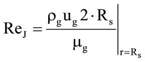 ,
,  is the Nusselt number without considering the blowing (
 for the sphere); Pr is the Prandtl number. In the case when the particle shape differs from the sphere the value of the
  number is to be determined by comparing the computed results with experiment.
2.2 The Model of Gas-Dynamic Processes
The diagram of a setup for testing the filling granular filters is presented in Figure 2.
It consists of a solid-fuel gas generator, from which the high-temperature combustion products enter the cooling chamber filled with the magnesium carbonate granules of the same size. Since the investigation of processes in the cooling chamber was the main objective of the present work, it is sufficient to use the balance (zero-dimensional) mathematical model (x0£x £ 0) for computing the gas-dynamic parameters in the combustion chamber of the gas generator
 ,
,  ,
,

Figure 2. Scheme of the experimental setup
 (6)
(6)
 ,
, 
where  are the total area of the burning surface of the fuel, its density, and the linear combustion velocity;
  are the free volume of the combustion chamber, which varies as the solid-fuel propellant burns out, the temperature, the pressure, and the gas density therein;
  are the adiabatic exponent of combustion products and their specific heat under a constant volume;
  are the specific internal energy and the heat of fuel combustion;
  are the area of the outlet section of the combustion chamber and the mean pressure in the cooling chamber near its left wall. The subscript refers to the parameters in the outlet section of the combustion chamber.
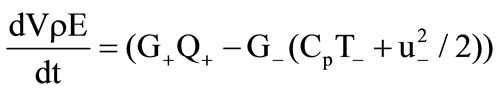
Gas flow in the cooling chamber ( ) is governed by the following system of equations:
 , (7)
, (7)
 , (8)
, (8)
 , (9)
, (9)
 , (10)
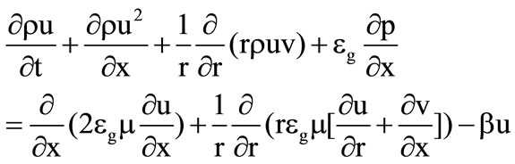 , (11)
 (12)
(12)
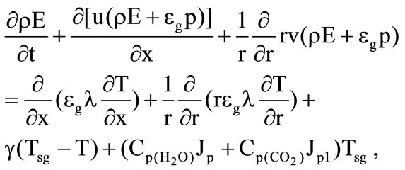 (13)
(13)
 ,
,  ,
,
 ,
,  ,
,
 ,
,
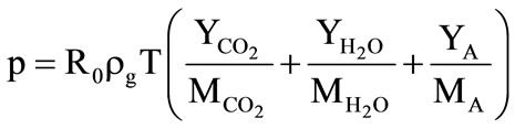
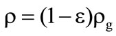
 where
where  are the total internal energy, the number and physical densities of particles (granules);
  are the coefficients of the specific heats, thermal conductivity and diffusion of gas;

 are the mass fractions of the carbon dioxide, water steam, and air, respectively, and their molecular weights;
  is the tempera ture of the granule surface. Its value is found from the solution of the problem of the heat propagation in the granule (see Subsection 2.1).
The values of extra gas supplies in equation (7) at the gasification of granules were found from the following expressions:

 ,
,  where n is the number of granules per unit volume (it is determined from the filter pouring conditions).
The drag coefficient  is calculated with the aid of a linear combination of the Ergan’s formula and the formula for the drag coefficient of a sphere [2]:
where  is the form parameter accounting for the granule shape deviation from the sphere;
  is the granule diameter.
The heat-transfer coefficient  was determined by the formula of the work [3].
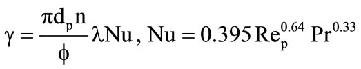 .
.
The boundary conditions were specified for system (7-13) as follows. At the impermeable walls of the cooling chamber, the no-slip conditions and the conditions for heat exchange absence were specified. At  in the inlet section of the chamber, through which the combustion products are supplied from the gas generator (
 see Figure 1):
 ,
,  ,
,  ,
, 
 ,
,  ,
, .
.
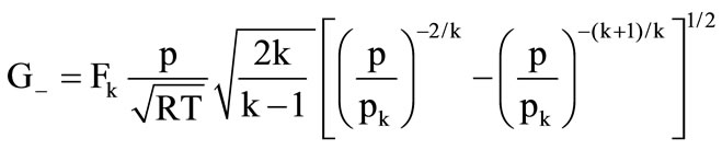
In the outlet section of the chamber ( see Fig. 1), where the outflow of combustion products may occur both in the subsonic and supersonic regime, their flow rate was specified, which was computed from the known gas-dynamic formulas for adiabatic flow
 if
if 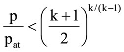 (subsonic outflow);
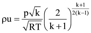 if
if  (supersonic outflow)
where  is the atmospheric pressure; k is the adiabatic exponent for the mixture of combustion products and gasification products. Its value was computed by averaging over the nozzle section of the quantity
 , where R is the gas constant of the mixture.
The “mild” boundary conditions were specified here for remaining flow parameters. The cooling chamber was assumed to be filled with air under the atmospheric pressure at the initial moment of time.
The upwind second-order LU difference scheme possessing the TVD properties, which was close to a scheme described in the work [4], was applied for numerical solution of Equations (7-13). The interaction between the gas and granules was taken into account on the basis of the splitting in terms of physical properties. The difference grid had the size  in the (x, r) plane, which ensured the computation of flow parameters with the accuracy of about 5%.
3. Some Computational Results
The computations were carried out for the following values of the cooling chamber parameters. The cooling chamber diameter is 80 mm; the mass of the filter granules is 0.6 kg. The temperatures of phase transitions for the first and second slug shells are  = 500 К and
  = 653 К, the heats of phase transitions
  = 326 kJ/kg and
  = 644 kJ/kg. The mass fractions of the gasification products of granules
 . The equivalent diameter of the granule
  = 5 mm. The diameter of the outlet section of the cooling chamber
  = 7 mm. The temperature of combustion products at the cooling chamber inlet amounted to 2290 К. The value of the adiabatic exponent in the combustion chamber of the gas generator k = 1.25.
Figure 3 shows a comparison of computed results with the results of test-bench tests (black circles) in terms of the temperature value in the outlet section of the cooling chamber. The value  [g] is the total mass of the formed gaseous products of the decomposition of filter granules. A fairly satisfactory agreement in the temperature values points to the performance of the proposed physical and mathematical model of the process. The amount of gas supply from the gas generator was insignificant, and the pressure level in the cooling chamber exceeded only slightly the atmospheric pressure level.
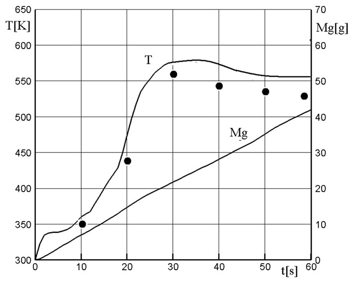
Figure 3. Temperature variation at the cooling chamber outlet

Figure 4. The pressure and temperature variation at x = 0 in the cooling chamber
The pressure and temperature behavior at the cooling chamber outlet at a higher value of gas supply from the combustion chamber of the gas generator is shown in Figure 4. The pressure drop after the first peak is related to the start of the gas outflow through the outlet section (the nozzle) of the cooling chamber. A further pressure growth is due to an additional gas supply of the gasification products of granules. As the intensity of granules gasification reduces this gas supply decreases, which results in the appearance of the second peak on the pressure curve and in the pressure decrease after it. As the solid-fuel propellant of the gas generator burns out the fraction of decomposition products of filter granules having a lower temperature increases in the gaseous mixture, which maintains the temperature at the cooling chamber outlet at a sufficiently low level.
Figures 5 and 6 show a comparison of the character of the variation of similar pressure and temperature curves for the active and passive filters. It was assumed in the case of the passive filter that its material (the same magnesium carbonate) is not subjected to destruction. A nearly linear pressure growth in the passive filter after the first peak is due to the use in the gas generator of a solid-fuel propellant with a so-called progressive combustion surface whose size increases with time. In the active filter, the extra gas supply from granules leads already to a nonmonotonous character of the pressure variation whose mean level proves to be higher than in the passive filter (Figure 5). This circumstance also leads to a reduction of the work time of the gas generator because the combustion velocity of the solid fuel increases with the pressure growth, and the solid-fuel propellant burns out faster. In the passive filter, the diminution of the temperature of combustion products of the gas generator occurs only at the expense of the heat absorptionby the filter granules, which leads to a practically linear temporal dependence of the gas temperature at the cool-
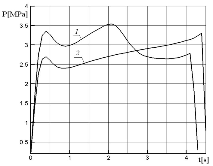
Figure 5. Pressure variation in the cooling chamber at x = 0 for the active (1) and passive (2) filters
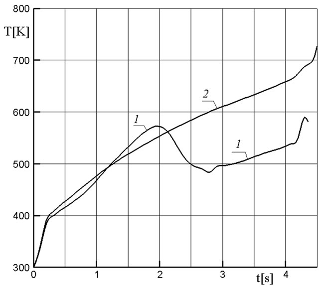
Figure 6. Temperature variation at the cooling chamber outlet for the active (1) and passive (2)
ing chamber outlet. In the active filter, the temperature at the chamber outlet proves to be much lower as a result of the mixing of low-temperature products of the decomposition of granules with combustion products (Figure 6).
4. Conclusions
1) The developed mathematical model describes sufficiently adequately the process of the cooling of hightemperature combustion products of solid-fuel propellants of the gas generators in the filters of active cooling.
2) Numerical modeling results showed a higher efficiency of cooling of combustion products at the use of active filters in comparison with passive filters.
REFERENCES
- E. P. Volkov, L. I. Zaichik and V. A. Pershukov, “Modeling of Solid Fuel Combustion,” Nauka, Moscow, 1994.
- L. E. Sternin, “Foundations of Gas Dynamics of Two-Phase Flows in Nozzles,” Mashinostroenie, Moscow, 1974.
- M. A. Goldshtik, “Transfer Processes in Granular Layer,” Published by the Institute of Thermophysics of the Siberian Branch of the USSR Academy, Science, Novosibirsk, 1984.
- S. Yoon and A. Jameson, “An LU-SSOR Scheme for the Euler and Navier-Stokes Equations,” AIAA Paper, 1987, pp. 87-600.