Energy and Power Engineering
Vol.6 No.7(2014), Article
ID:48105,8
pages
DOI:10.4236/epe.2014.67017
Design of Real Time Battery Management Unit for PV-Hybrid System by Application of Coulomb Counting Method
Apiwat Ausswamaykin1, Boonyang Plangklang2
1Department of Electrical Engineering, Faculty of Engineering Rajamangala University of Technology IsanKhonkaen Campus, Khon Kaen, Thailand
2Department of Electrical Engineering, Faculty of Engineering Rajamangala University of Technology Thanyaburi, Pathum Thani, Thailand
Email: apiwat4321@hotmail.com, boonyang.p@en.rmutt.ac.th
Copyright © 2014 by authors and Scientific Research Publishing Inc.
This work is licensed under the Creative Commons Attribution International License (CC BY).
http://creativecommons.org/licenses/by/4.0/


Received 29 May 2014; revised 1 July 2014; accepted 10 July 2014
ABSTRACT
This paper presents a real-time battery management unit designed by applying the Coulomb counting method and intended for use in an integrated renewable energy system for PV-Hybrid power supply. Battery management is required to stabilize hybrid systems and extend battery lifetimes. The battery management unit is divided into three main stages. Firstly, analysis of the basic components of the battery type used in the system is considered. Secondly, the state of charge (SOC) estimation method and the deterioration factor of the battery are analyzed. Finally, the overall battery management system, including a computer-based measurement and control unit, is constructed. The control system displays real-time information through LabVIEW 8.5 by estimating the state of charge through various measurements. The system will issue alerts when malfunctions are detected, and the operator can analyze and react to the system in real time to stabilize the system and extend the battery lifetime.
Keywords:Battery Management System, PV Hybrid Power Supply

1. Introduction
Electrical energy demand increases every year and most electrical energy production begins with coal, natural gas and petroleum, which affect the environment through pollution. Therefore, electrical energy from a hybrid renewable energy source has become an attractive alternative for supplying electrical energy.
Hybrid renewable energy systems (HRES) are becoming popular for power generation in remote areas due to advances in renewable technologies and increasing petroleum products prices. A hybrid energy system generally consists of two or more renewable energy sources used together to increase the system’s efficiency and balance the energy supply. The most frequently used type of HRES is a photovoltaic (PV) array coupled to a generator. Hybrid energy systems often yield greater economic and environmental returns than stand-alone photovoltaic systems. To stabilize the HRES, an energy storage system is required to supplement the generator when the PV cannot generate electricity, e.g., at night or under cloud coverage. The normal HRES energy storage unit is a battery system. The primary concerns with these battery storage systems are performance, lifetime and durability. Therefore, in these applications, a battery management system (BMS) is needed to control the working conditions of the battery, stabilizing the system and extending the useful life of the battery.
2. Basic Elements of a Battery in Solar Energy System
In practice, all types of battery can be used in renewable energy systems. We consider lead-acid, nickel-cadmium, and nickel-iron batteries and find that the battery type most commonly used in renewable energy systems is the deep-discharge lead-acid battery. Lead-acid batteries are preferred because of factors including the price, performance and battery lifetime, as shown in Table1
3. Theory of the Lead-Acid Battery [2]
The lead-acid battery is frequently used in automobiles and other applications in which weight is not a concern. In the 1970s, the valve-regulated lead-acid battery (or the “sealed lead-acid battery”) was developed; this battery used a gel electrolyte instead of a liquid, allowing the battery to be used in a variety of positions without introducing leakage. In the battery’s discharged state, both the positive and negative plates are lead sulfate (PbSO4), and the electrolyte is primarily water, having lost most of its dissolved sulfuric acid (H2SO4). The discharge process is driven by the conduction of electrons from the negative plate to the positive plate through an external circuit. In the charged state, each cell contains negative plates of elemental lead (Pb) and positive plates of lead oxide (PbO2) in a sulfuric acid electrolyte.
The charging process is driven by the forcible removal of electrons from the positive plate and the forcible introduction of them to the negative plate using a charging source. There are several types of lead-acid batteries, and the type most suited for use with renewable energy systems is the deep discharge type because this design is intended to provide small amounts of power continuously over long periods and discharge up to 80% of the total battery capacity without damaging the battery [3] [4] .
4. State of Charge Estimation Method
The state of charge (SOC) is the equivalent of a fuel gauge for a battery pack. The units of SOC are percentage points: 0 percent is empty, and 100 percent is full. An alternate form of the same measure is the depth of discharge (DOD), which is one minus the SOC (i.e., 100 percent is empty, 0 percent is full). The SOC is commonly used to discuss the current state of a battery in use, while the DOD is most often used when discussing the lifetime of the battery after repeated use.
State estimation must be accurate in a battery management system, as the system controls the performance of the battery to extend its lifetime. In practical applications, estimating the SOC is problematic because the load

on a hybrid system is not smooth or stable.
It is therefore necessary to estimate the state of charge of a battery for use in a battery management system (BMS) designed to increase the performance and reliability of the battery.
Many methods of estimating the state of charge exist. Table 2 presents a comparison of SOC estimation techniques.
The paper presents a Coulomb counting SOC estimation method for application in PV-hybrid power supply battery management systems because this method can be monitored in real-time under unstable load consumption conditions and is easy to calculate.
5. SOC Estimation by Coulomb Counting
The state of charge is estimated by measuring the battery current and integrating it over time. However, this method suffers from long-term drift and lack of a reference point. Therefore, the SOC must be re-calibrated on a regular basis, e.g., by resetting the SOC to 100 percent when a charger determines that the battery is fully charged.
For real-time estimation, this method utilizes Equation (1) with real-time measurements from the sensors and an initial SOC of 100 percent [6] -[11] .
 (1)
(1)
where
![]() is Real-time state of charge (%).
is Real-time state of charge (%).
 is Initial state of charge (%).
![]() is Real-time discharge current (A).
is Real-time discharge current (A).
 is Capacity of battery (Ah).
6. Deterioration Factor of Battery [12]
Ambient temperature effects: The lead-acid battery consists of a positive lead oxide plate and a negative lead plate. Both plates are dipped in sulfuric acid, and the temperature affects the rates of corrosion and deterioration of the plates. Temperature specifications are given by IEEE1184-1994 [13] .
Float charge voltage: A charging voltage different from the target voltage will affect the deterioration of the plate. When the floating charge voltage is under the target, the battery will experience sulfating at the positive plate and negative plate. If the floating charge voltage is over the target, then the battery will lose water.
Discharge cycle: Repeated discharge cycles cause battery deterioration. The battery plates will exhibit corrosion due to battery deterioration.
7. Proposed Battery Management System [14] [15]
This section presents the basic theory of the lead-acid battery, techniques for estimating the state of charge and means of determining the deterioration state of the battery. The battery management system for PV-hybrid power supplies is summarized in Figure 1 and Figure 2.
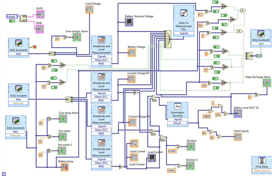
Figure 1. BMS programmatic control.

Figure 2. BMS monitoring display.
Figure 1 shows the program for battery control and SOC calculation. Figure 2 presents the monitoring display of the battery management system, which comprises 4 sections. Section 1 presents graphs of the voltage and load current of the battery. Section 2 shows digital values indicating the battery voltage, PV voltage, PV charge current and DC generator charge current. Section 3 presents a graphic display of the battery SOC. Finally, Section 4 issues alerts if the system detects malfunctions so that the operator can analyze and react to the system in real-time.
7.1. Data Acquisition
All algorithms that the BMS uses take measured data as input information. Therefore, the accuracy, sampling rate and characteristics of front-end filtering are crucial to the BMS and application-dependent.
The BMS also handles communication between the BMS and other onboard and off board devices. Depending on the application, different interface system may be used for data exchange. This paper utilized a Local Area Network: LAN by Nic DAQ-9188 and module NI9335, NI9227, NI9211 and NI9401, as shown in Figure 3.
7.2. Electrical Management
The input parameters of the electrical management system are the current, voltage and SOC. This system controls the charging and discharging processes.
7.3. Thermal Management
A thermal management is necessary for most high-power applications and high-temperature batteries. The thermal management system equalizes the temperature of the battery and cools it when necessary. Liquid or airbased thermal systems are used. This paper presents an air-base battery cooling system, with the battery operated at 35˚C and a stop condition at 50˚C.
7.4. Safety Management
The safety management system protects the battery against critical operation conditions. The design constraints employed in this paper are:
• The deep discharge cycle control criterion stops battery operation when the battery voltage reaches 80% DOD.
• The overcharge voltage control criterion controls the battery voltage to not exceed 115 percent of the rate voltage.
7.5. Battery State Determinations
The battery state is a crucial input parameter for the management system. For SOC determination in this paper

Figure 3. Data acquisition block of the Coulomb counting method.
employs the Coulomb counting method to determine the SOC of the battery. The results of the BMS employing the Coulomb counting method will be compared with standard tests performed on MTB-series module (Machine for Test Battery, MTB) at the RMUTT Laboratory as in Figure 4 and Figure 5 using lead-acid batteries supplying 12 V and 5.5 Ah. The discharge current is 1A. The results of this comparison are shown in Figure 6.
Figure 6 compares the SOC of the two systems, starting from 100 percent. The Coulomb counting method has 10 percent error relative to the MTB-series estimation.
8. Conclusions
This paper presents a real-time battery management system for use with PV-hybrid power supplies. The BMS employs the Coulomb counting method.
The designed system has a protection system, a control system and a monitoring system. Data acquisition from the battery is performed using LabVIEW8.5 and the Nic DAQ-9188 module and serves as the input parameters to the other systems.
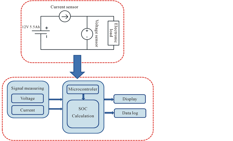
Figure 4. SOC calculation by MTB-series.
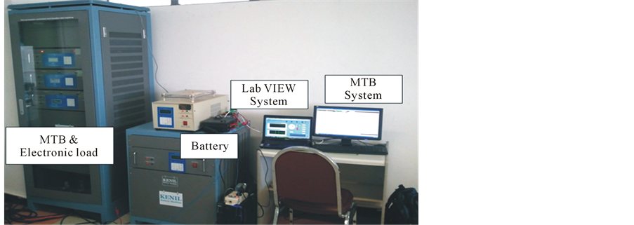
Figure 5. SOC testing system MTB-series at RMUTT Lab.

Figure 6. Results of comparison of SOC and MTB in LabVIEW.
The state of charge of the system is estimated using the Coulomb counting method in real time. The method has been verified by comparison with the Battery Testing MTB-series. The errors between the results of both systems are estimated at 5 percent. The system will issue alerts when the system detects malfunctions, and the operator can analyze and react to the system in real time to make the system stabilized and extend the lifetime of the battery. Therefore, the proposed BMS using the Coulomb counting method can be used for managing batteries in PV-hybrid systems.
References
- Plangklang, B. (2010) Photovoltaic System Technology. Rajamangala University of Technology, Thanyaburi.
- http://en.wikipedia.org/wiki/Lead-acid_battery
- Ladener, H. (1996) Solare Stromversorgung: Grundlagen, Planung, Anwenddung. ÖkobuchVerlag, Freiburg, 79-103.
- Garche, J. and Harnisch, P. (1999) Batterien in PV-Anlagen. In: Schmid, J., Ed., Photovol-Taik: Strom aus der Sonne, Technologie, Wirtschaftlichkeit und Marktentwick-Lung, Müller, Heiderberg, 143-174.
- Chen, Z.H. (2011) Battery State of Charge Estimation Based on a Combined Model of Extended Kalman Filter and Neural Networks. The 2011 International Joint Conference on Neural Networks (IJCNN), San Jose, 31 July-5 August 2011, 2156-2163.
- Rodrigues, S., Munichandraiah, N. and Shukla, A.K. (2000) A Review of State-of-Charge Indication of Batteries by Means of A.C. Impedance Measurements. Journal of power Sources, 87, 12-20.
- Pascoe, P.E. and Anbuky, A.H. (2004) VRLA Battery Discharge Reserve Time Estimation. IEEE Transaction on Power Electronic, 19, 1515.
- Matthias, D. (2006) Dynamic Model of a Lead Acid Battery for Use in a Domestic Fuel Cell System. Journal of Power Sources, 161, 1400-1411. http://dx.doi.org/10.1016/j.jpowsour.2005.12.075
- Olivier, T. and Louis, A.D. (2009) Experimental Validation of a Battery Dynamic Model for EV Applications. EVS24 International Battery. World Electric Vehicle Journal, 3, 1-10.
- Shepherd, C.M. (1965) Design of Primary and Secondary Cells—Part 2. An Equation Describing Battery Discharge. Journal of Electrochemical Society, 112, 657-664.
- Sabine, P., Marion, P. and Andresa, J. (2001) Method for State of Charge Determination and Their Application. Journal of Power Sources, 96, 113-120.
- Sukrrmoak, K. (2009) Deteioration Factor of Battery. PEC Technology (Thailand) ltd., Bangkok.
- IEEE (2005) Guide for Selection and Sizing of Batteries for Uninterruptible Power Supply. IEEE Std., 1184-1994.
- Jossen, A. (1999) Battery Management Systems (BMS) for Increasing Battery Life Time. Center for Solar Energy and Hydrogen Research (ZSW Ulm), Helmholtzstr.
- Atia, Y., Zahran, A.M. and Al-Hossain, A. (2010) Solar Cell Curves Measurement Based on LabVIEW Microcontroller Interfacing. Proceedings of the 12th WSEAS International Conference on Automatic Control Modeling & Simulation, 59-64.