Energy and Power Engineering
Vol.5 No.4(2013), Article ID:33273,7 pages DOI:10.4236/epe.2013.54032
Applying MILP for 27-Level CMLIs to Obtain Low THD Values over Wide Voltage Range
Electronics Research Institute, Giza, Egypt
Email: mahmdali42@yahoo.com
Copyright © 2013 Mahmoud El-Bakry. This is an open access article distributed under the Creative Commons Attribution License, which permits unrestricted use, distribution, and reproduction in any medium, provided the original work is properly cited.
Received April 1, 2013; revised May 2, 2013; accepted May 10, 2013
Keywords: Cascaded Multilevel Inverters; Harmonic Elimination; Harmonic Values Minimization; Mixed Integer Linear Programming; Total Harmonic Distortion
ABSTRACT
The 27-level cascaded multilevel inverter (CMLI) is a popular CMLI, since it can produce an output voltage with nearly sinusoidal wave form and may be realized as a trinary asymmetric CMLI that consists of only three H-bridges. A new approach using a mixed integer linear programming (MILP) model is applied, that can determine the switching angles of this CMLI that minimize the values of any undesired harmonics. The model is applied first to determine the number of harmonics to be minimized to obtain least percentage total harmonic distortion (%THD) utilizing the 13 positive levels of the inverter. The obtained result is then included in the model and it is solved for different values of the output voltage. Single phase and three phase cases are investigated. The results show very low values of %THD and low order harmonics over wide voltage range till the 91st harmonic in both cases, which agree with the IEEE standards 519-1992 for voltage distortion limits till 161 kv.
1. Introduction
Cascaded multilevel inverter (CMLI) is the most recent and popular type of multilevel inverters, that synthesizes a desired sinusoidal voltage from several separate dc voltage sources. The general construction of the CMLI is shown per phase in Figure 1. It consists of S number of H-bridges fed with dc voltages sources . The output voltage is usually constructed in a stair case shape with quarter wave symmetry, in Figure 2, to approach synthesizing a sinusoidal wave form, [1].
If all the dc sources are of equal value, say E, the CMLI is called symmetric. In this case the maximum number of the positive levels of the inverter is S and is obtained by switching on the dc sources sequentially, and these levels may take the values . While if the dc sources are of unequal values, the CMLI is referred to as an asymmetric CMLI. In this case the maximum number of the positive levels of the inverter can be increased greatly, since it could be possible to switch on some dc sources positively or negatively within the positive half cycle of the output voltage, thus adding additional positive levels. Generally, the possible positive levels of an asymmetric CMLI are all the positive values of
 , where each of
 , and ps can take one of the values −1, 0 or +1. The number of all possible levels is (3)S, some of them may be redundant. Increasing the number of levels of the inverter means that its staircase output wave form can approach more closely a sinusoidal wave form, which in turn means that the output voltage lower order harmonic values and their total harmonic distortion could be reduced greatly, and this makes asymmetric CMLIs more popular for practical applications [2].
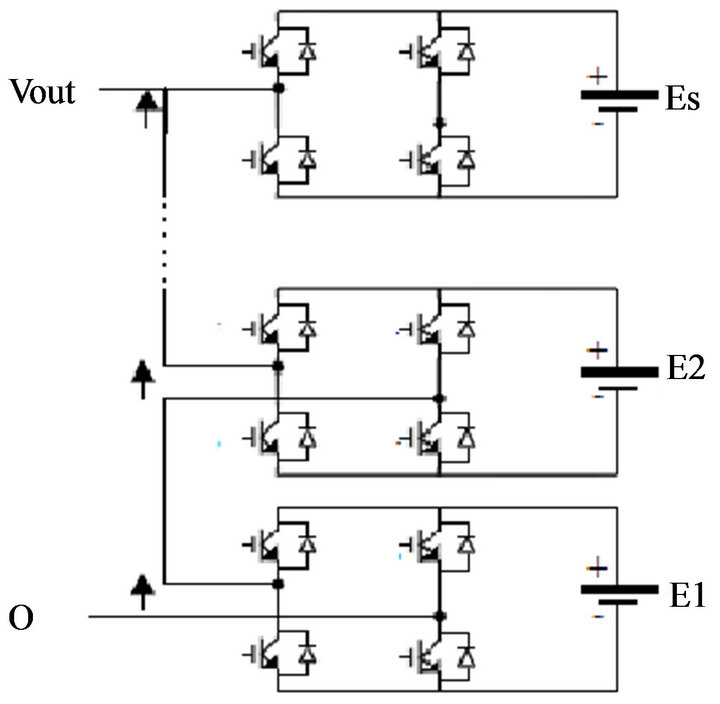
Figure 1. A cascaded multilevel with S dc sources.
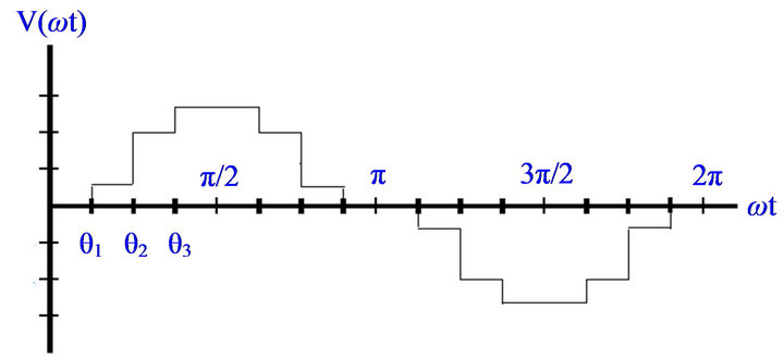
Figure 2. A staircase output voltage wave form with 3 positive levels.
To obtain a staircase output voltage wave form with equal step heights in an asymmetric CMLI, the following uniform step sufficient conditions may be satisfied by the dc sources . [3]:
1) ,
,  , and each of
 , and ES is an integer multiple of E1.
2)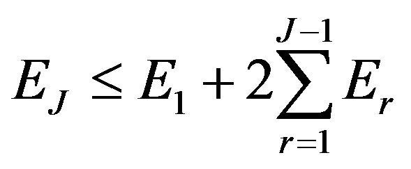 , and
, and 
It is possible to obtain the maximum number of levels in an CMLI, i.e. (3)S non-redundant or different levels, by replacing the inequality sign in the second condition with an equality sign. Thus considering three H-bridges with E1 = E we get E2 = 3E and E3 = 9E and the associated three H-bridges form the well known trinary asymmetric CMLI with the (3)3 = 27 levels: 
 and ±13E. Trinary asymmetric CMLIs can give better approximation of a sine wave than other asymmetric CMLIs, [4]. The 27-level asymmetric CMLI is thus recommended for many applications, such as for induction motors and traction drives, [5-7].
In this paper the 27-level CMLI is considered, and a new approach depending on linear programming for determining the switching angles of this inverter that minimize the values of undesired harmonics is introduced and applied for single phase and three phase inverters.
2. A Proposed Approach for Determining the Switching Angles of the Inverter
A fundamental issue for a CMLI is to find the switching angles (times) of the inverter H-bridges semiconductor power switches that produce the required fundamental voltage and at the same time eliminate or reduce the values of undesired specific low order dominant harmonics .Many methods are given in the literature for obtaining the switching angles of symmetric as well as uniform step asymmetric CMLIs. These are mainly:
1) Using sinusoidal pulse width modulation, [8-12].
2) Using a selective harmonic elimination technique, where the zero equations of the undesired harmonics with the equation of the desired amplitude of the main harmonic as functions of the switching angles are solved directly or by applying genetic algorithms, [1,13-17].
3) Using the method of minimizing the total harmonic distortion, [18,19].
However, all these methods are suitable mainly for CMLIs with small number of positive levels, and thus are not adequate for the 27-level inverter with 13 positive levels.
In addition, the author has introduced a method based on a general linear programming model that could be applied to minimize the values of the undesired harmonics, [20,21]. This linear programming (LP) model has the following advantages over other methods discussed in the literature, [22]:
1) This model is flexible. It allows minimizing the values of harmonics of any order and any number, independent of the number of inverter levels, under any required reasonable value of the main harmonic.
2) LP constraints may be inequality constraints, so a feasible solution could be almost found, unlike harmonic elimination method which may give no feasible solution due to not satisfying the trigonometric equalities imposed.
3) LP constraints allow minimizing harmonics values with different weighting factors according to the harmonic order. Low order harmonics values could be minimized much more than higher order ones.
4) LP provides global optimal solution of the problem over the whole solution space, unlike some other optimization methods that give a local optimal solution near an initial solution, which may not be a global optimal solution.
5) Many software packages are available for solving LP models, even with huge number of variables and constraints, in a moderate time. They are suitable for large problems that could not be easily solved with other methods.
6) The model can be applied even for asymmetric CMLIs with non uniform steps by adding additional constraints, [23].
7) The model contains many parameters that could be selected arbitrarily. Many optimum solutions could be obtained for the same problem corresponding to different values of these parameters, and thus allowing for selecting the best one.
The mathematical model of this approach is first given, and then applied for the single phase and the three phase 27-level CMLI. The model is applied first to determine the number of harmonics to be minimized that lead to least %THD. By including this result in the model and solving it for different amplitudes of the output main harmonic, the switching patterns that give minimum values of undesired harmonics are obtained.
3. The Proposed Mathematical Model
The general uniform step asymmetric CMLI, or symmetric CMLI, is considered, where all the inverter levels are spaced equally with a step height E.. It is assumed, without loss of generality, that the inverter levels are equally spaced by 1 volt, i.e. normalized with respect to the dc voltage E. It is assumed also that the inverter output voltage wave form F(wt) has a quarter wave symmetry, as that shown in Figure 2. The pattern of this function is generated by on and off switching of the inverter H-bridges semiconductor power switches, and is completely determined by defining the switching pattern over the interval . The basic approach depends on dividing this interval into N equal small subintervals, starting at the angles
 , till (N − 1)τ., where τ = π/2N, Figure 3.
The positive integer values XI,  are defined over each subinterval, to represent the required instantaneous output voltage level value F(wt) of the inverter, so that F(wt) is defined over the interval
  by:
by: 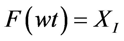 for
for 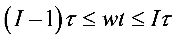 and
and 
The Fourier series expansion of F(wt) is an odd-sines series given by:
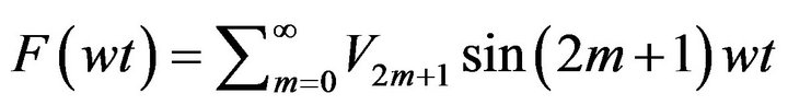 where
where
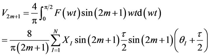 (1)
(1)
where (2m + 1) is the order of the harmonic,  , τ = π/2N, and
 .
.
The value of the amplitude of main harmonic corresponds to V1, and is obtained by substituting m = 0 in Equation (1).
Equation (1) shows that V2m + 1 for any value of m is a linear function of the integer values XI, .
.
Variations of the values of XI from a subinterval to a next one determine the required switching angles of the inverter from one level to another.
It is required to find the values of XI that minimize the values of some undesired harmonics. A mixed integer linear programming (MILP) problem is formulated as
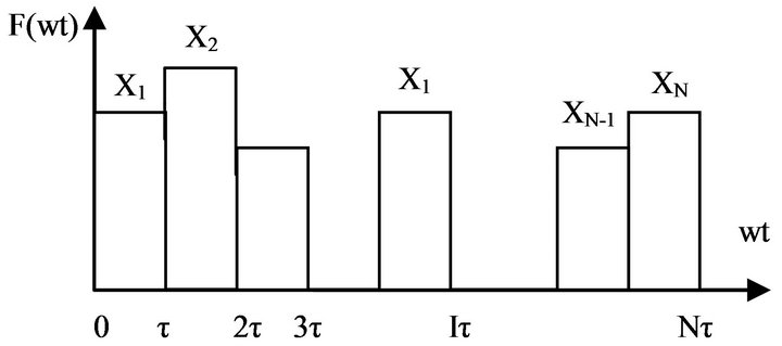
Figure 3. Representation of F(wt) by XI,  over the interval 0 ≤ wt ≤ π/2.
follows, [11]:
Minimize ε, subject to the constraints:
 (2)
(2)
 (3)
(3)
 , for
, for , and
, and  (4)
(4)
 and integer for
  (5)
(5)
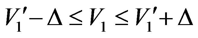
In the main harmonic constraint (2)  is the required amplitude of the main harmonic. Δ is a small incremental value,
  , arbitrary chosen and included in the main harmonic constrain to ensure obtaining an optimum solution, since an equality constraint may give a high value of ε or even an unfeasible solution., due to the trigonometric nature of the constraints. The value of Δ is taken of the order of 1% of
 , so that the obtained value of V1 does not differ practically from the required value of
 .
.
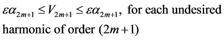
In constraint (3) V2m + 1 is given by Equation (1), for V1 and the undesired harmonics, and α2m + 1 is a weighting factor for the undesired harmonics, to enable reduction of harmonics with different upper bounds according to their order.
By constraints (4) the positive staircase wave form shape is assured with maximum height L, where L is the number of positive voltage levels of the inverter.
Constraint (5) is the integer constraint on XI.
Once all the parameters of this MILP model are given, an optimum solution could be obtained that gives the values of XI and ε using any of the well known operations research software packages, e.g. “LINGO” software [24].
4. Selecting the Model Parameters
In the following sections this model is applied for the 27-level CMLIs, taking the number of subintervals N = 180, that corresponds to a subinterval angular width of 90˚/180 = 0.5˚, Figure 3.
The model is first solved with the constraint (2) replaced by:
 (2’)
(2’)
to minimize undesired harmonics for all amplitudes of the output voltage greater than L, normalized with respect to E, while utilizing all the levels of the inverter (L = 13).
The model is solved for the following two cases:
1) Minimizing all undesired harmonics equally, i.e. taking in constraint (3) the values of α2m+1 = 1 for all undesired harmonics.
2) Minimizing the harmonics with an increasing weighting proportional to the order of the harmonic, by taking α2m + 1= 2m + 1 for all undesired harmonics.
For each of the above two cases the model is solved for minimizing low order harmonics till a harmonic of order k, for different values of k, then selecting the value of k that leads to least %THD, where the %THD is defined by:
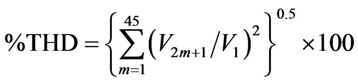 , (6)
, (6)
i.e. the %THD is calculated till the 91st harmonic.
Then the model is solved, using this value of k, to minimize low order undesired harmonics till the kth harmonic for different values of the required output voltage  between 7 and 15, using the constraint (2) and taking Δ = 0.1.
By this way the switching patterns of the inverter at different values of the output voltage that minimize the values of low order harmonics with least %THD are obtained. This procedure is carried out next for the single phase and three phase CMLIs.
5. Solution of the Model for the 27-Level Single Phase CMLI
5.1. Solution for Different Values of the Undesired Harmonics
Figure 4 shows the %THD obtained by solving the model, with the voltage constraint (2’), to minimize the odd harmonics  till the kth harmonic for different values of k and for the two cases: equal weightings and increasing weightings of the undesired harmonics. The figure shows that the least %THD (= 2.67%) is obtained by minimizing the undesired harmonics equally till the 31st harmonic, and this is obtained at V1 = 13.21.
5.2. Solution for Different Amplitudes of the Output Voltage
The model is solved using the voltage constraint (2) for some values of  between 8 and 14 to obtain the switching angles of the inverter that minimize the odd harmonics equally from the 3rd till the 31st harmonic. Figure 5 shows for each value of V1, that corresponds to
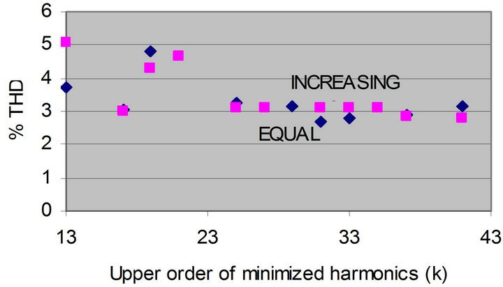
Figure 4. The %THD for different minimized harmonics.
 and 14, and for V1 = 13.21 the value of %THD and the value %Vhmax ,which represents the maximum percentage absolute amplitude of the undesired harmonics relative to the main harmonic among all harmonics from the 3rd till the 91st harmonic. It is shown that the % THD is less than 5% and that the %Vhmax is less than 3% over the wide voltage range.
Some results obtained from the detailed solution of the model at V1 = 13.21 are given next. The value of %THD = 2.67% and of %Vhmax = 0.9%. For this value of V1 Figure 6 shows the obtained values of XI. The 13 switching angles of the inverter are: 1.5˚, 4.5˚, 10.5˚, 15.5˚, 19˚, 25˚, 29˚, 35˚, 39.5˚, 46.5˚, 52.5˚, 60.5˚ and 71˚. Figure 7 shows the switching patterns of the three H-bridges of the inverter during the positive quarter cycle of the main harmonic, assuming a uniform step asymmetric CMLI. The 1E H-bridge is switched 9 times on and 8 times off. The 3E H-bridge is switched 3 times on and 2 times off and the 9E H-bridge is switched one time on. If the 27
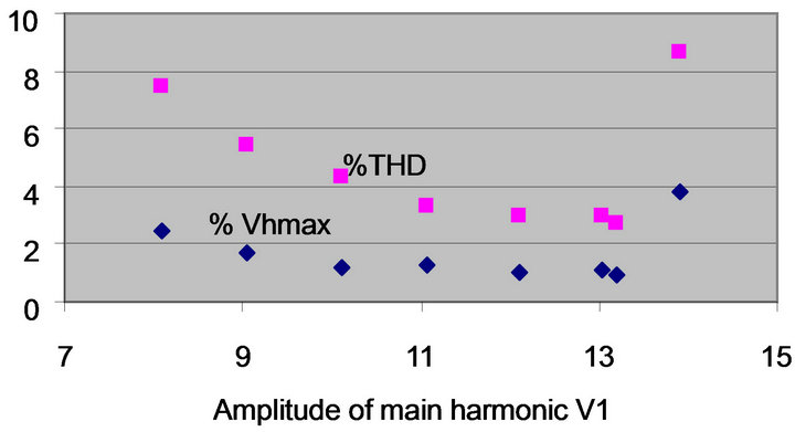
Figure 5. The values of %THD and %Vhmax against V.
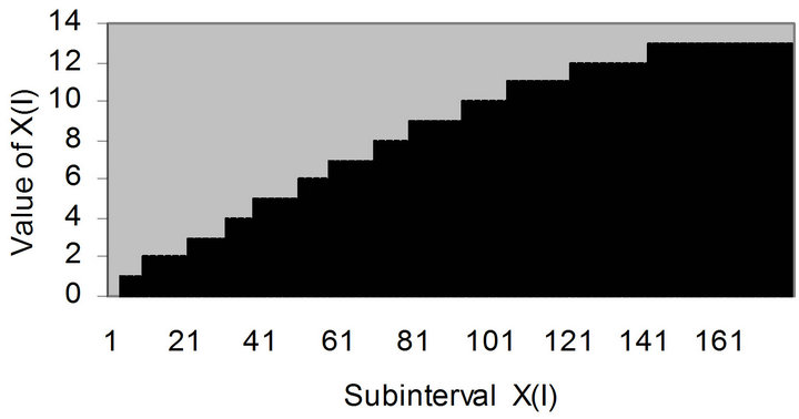
Figure 6. Values of XI that gives V1 = 13.21.
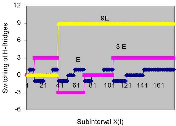
Figure 7. Switching patterns of the H-bridges for V1 = 13.21.
level inverter is constructed as a symmetric CMLI it will need 13 H-bridges, that would be switched on consequently 13 times only during the positive quarter cycle of the main harmonic. This shows that asymmetric CMLIs suffer from more switching losses than symmetric CMLIs, but this does not represent a serious problem with recent developments of semiconductor power switches with low switching losses, [25].
Figure 8 shows the obtained percentage values of the harmonics relative to the main harmonic from the 3rd till the 91st harmonic, and a 5% of the main harmonic at V1 = 13.21.
Similar results could be obtained when solving the model at any value of the output voltage V1 between 8 and 14.
Noting that the values of V1 are normalized with respect to the dc voltage E.
6. Solution of the Model for the 27-Level Three Phase CMLI
In a balanced three phase operation the triplen odd harmonics, i.e. the 3rd, 9th, 15th··· and so on, are self cancelled in the output line voltage assuming a star connected three phase inverter. The procedure carried out in Section 5 with the single phase asymmetric CMLI is repeated while excluding the triplen odd harmonics, as follows:
6.1. Solution for Different Values of Undesired Harmonics
Figure 9 shows the %THD obtained by solving the model, with the voltage constraint (2’), to minimize the nontriplen odd harmonics till the kth harmonic for different values of k and for the two cases: equal weightings and increasing weightings of the undesired harmonics.
The figure shows that the least %THD (=1.67%) is obtained by minimizing the undesired harmonics equally till the 31st harmonic, and this is obtained at V1 = 13.87.
6.2. Solution for Different Amplitudes of the Output Voltage
The model is solved using the voltage constraint (2) for
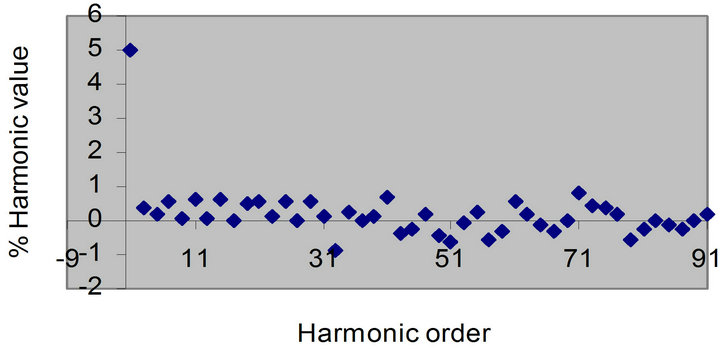
Figure 8. % Values of harmonics for V1 = 13.21.
some values of  between 6 and 15.5 to obtain the switching angles of the inverter that minimize the non-triplen odd harmonics equally from the 5rd till the 31st harmonic. Figure 10 shows for each value of V1, that correspond to
  and 15.5, and for V1 = 13.87 the values of % THD and %Vhmax, as defined in Sections 4 and 5, for the non-triplen harmonics from the 5th till the 91st harmonic. It is shown that the % THD is less than 2.5% and that the %Vhmax is less than 1.5% over the voltage range 13 ≤ V1 ≤ 15, noting that the values of V1 are normalized w. r. t. E.
As a detailed solution example, the least values of % THD and % Vhmax are obtained at V1 = 13.87: % THD = 1.67% and % Vhmax = 0.69%. For this value of V1, Figure 11 shows the obtained values of XI.. The 13 switching angles of the inverter are: 2˚, 3˚, 8.5˚, 13.5˚, 17˚, 20˚, 24.5˚, 28.5˚, 33.5˚, 39.5˚, 49.5˚, 52.5˚ and 69˚.
Figure 12 shows the corresponding switching patterns of the three H-bridges of the inverter during the positive quarter cycle of the main harmonic, assuming a uniform
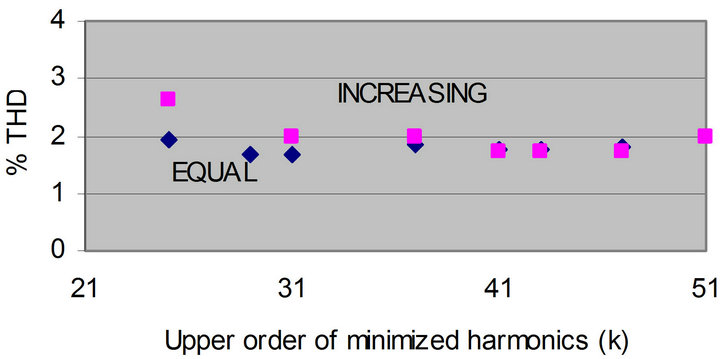
Figure 9. The % THD for different minimized harmonics.
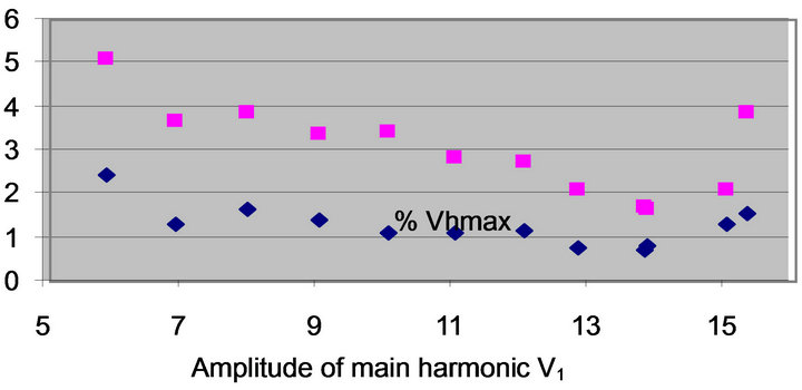
Figure 10. The values of % THD and %Vhmax against V1.
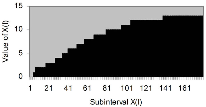
Figure 11. Values of XI that gives V1 = 13.87.
step asymmetric CMLI. The three H-bridges are switched as many times as for the single phase asymmetric CMLI, shown in Figure 7.
Figure 13 shows the obtained percentage values of the harmonics relative to the main harmonic from the 5th till the 91st harmonic, excluding the triplen harmonics, and of 5% of the main harmonic for V1 = 13.87.
7. Conclusions
This paper introduces a general approach for minimizing the values of the undesired harmonics produced by symmetric or asymmetric uniform step CMLIs using a mixed integer linear programming (MILP) model. Using MILP for this problem has many advantages over other methods given in the literature, and specially of being suitable for CMLIs with large number of levels. This approach is applied first to determine the number of harmonics to be minimized in order to obtain least percentage total harmonic distortion till the 91st harmonic, then the result is included in the model and it is solved for different values of the output voltage, to get the switching pattern that minimize the harmonics values. Solutions for single phase and three phase 27-level CMLIs are given.
It should be noted that the proposed approach could be applied for symmetric or uniform step asymmetric CMLIs. A 27-level symmetric CMLI needs 13 series connected H-bridges per phase, with equal dc sources. The corresponding asymmetric CMLI needs only 3 series connected H-bridges per phase. This will be at the cost of
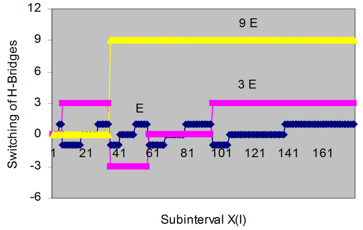
Figure 12. Switching patterns of the H-bridges for V1 = 13.8.
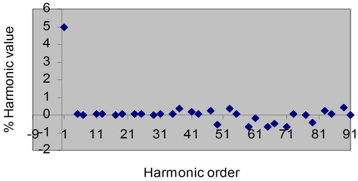
Figure 13. % values of harmonics for V1 = 13.87.
more switching losses, but this does not represent a serious problem with the recent development of power semiconductor switches with low switching losses. In addition, asymmetric CMLIs need semiconductor power switches with higher voltage ratings, and thus are more suitable for medium voltage applications, while symmetric CMLIs are more suitable for high voltage applications, [1].
In all the cases discussed the applied MILP assumes dividing the quarter half cycle of the main harmonic in N = 180 subintervals to obtain reasonable results with moderate solution time that differs from few seconds to few minutes on a usual personal computer. Increasing the number of subintervals N may lead to solutions that have lower percentage values of the minimized undesired harmonics %Vhmax and their %THD. However, the obtained values agree well with the IEEE standard 519- 1992 for voltage distortion limits in power systems, [26]. This standard puts upper limits of 5% and 3% for %THD and %Vhmax respectively for output voltages ≤ 69 kv, and upper limits of 2.5% and 1.5% for %THD and %Vhmax for output voltages between 69 and 161 kv. Thus using the results of this paper, the single phase 27-level CMLI could be used for output voltage values till 69 kv, and the 3 phase 27-level CMLI could be used for output voltage values till 161 kv.
REFERENCES
- M. N. Ben Nasr, A. Kebir and F. B. Ammar, “Cascaded H-Bridges Symmetrical 11-Level Optimization,” Proceedings of 14th International Middle East Power Systems Conference (MEPCON’2010), Cairo, 19-21 December 2010, pp. 465-470.
- F. Khoucha, M. S. Lagoam, A. Kheloui and M. E. Benbouzid, “A Comparison of Symmetrical and Asymmetrical Three Phase H-Bridge MLI for DTC Induction Motor Drives,” IEEE Transactions on Energy Conversion, Vol. 26, No. 1, 2011, pp. 64-72. doi:10.1109/TEC.2010.2077296
- J.Song-Manguell, S. Mariethoz, N. Veenstra and A. Ruter, “A Generalized Design Principle of a Uniform Step Asymmetric Multilevel Converter for High Power Conversion,” European Conferences on Power Electronics and Applications EPE’01, Graz, 27-29 August 2001, pp. 1-12.
- B. Sujanarko, M. Ashari and M. H. Parnoma, “Improved Voltage of Cascaded Inverters Using Sine Quantization Progression,” Indonesian Journal of Electrical Engineering, Vol. 8, No. 2, 2010, pp. 123-130.
- M. Rotello, G. Penailillo, J. Pereda and J. Dixon, “PWM Method to Eliminate Power Soueces in Nonredundant 27 Level Inverter for Machine Drive Applications,” IEEE Transactions on Industrial Electronics, Vol. 56, No. 1, 2009, pp. 194-201. doi:10.1109/TIE.2008.927233
- K. Ramani and A. Krishnan, “New Hybrid 27 Level MLI Fed Induction Motor Drive,” International Journal of Recent Trends in Engineering, Vol. 12, No. 5, 2009.
- J. Dixon, J. Preda, C. Castillo and S. Bosch, “Asymmetrical Multilevel Inverters for Traction Drives Using Only One DC Supply,” IEEE Transactions on Vehicular Technology, Vol. 59, No. 8, 2010, pp. 3736-3743. doi:10.1109/TVT.2010.2057268
- R. Seyezhai and B. L. Mathur, “Implementation and Control of Variable Frequency ISPWM Technique for an Asymmetric Multilevel Inverter,” European Journal of Scientific Research, Vol. 39, No.4, 2010, pp. 558-568.
- B. Sujanarko, M. Ashri, M. H. Parnomo and O. Penangsang, “Advanced Carrier Based PWM in Asymmetric Cascaded Multilevel Inverter,” International Journal of Electrical & Computer Sciences, Vol. 10, No. 6, 2010, pp. 47-51.
- J. I. Leon, S. Kouro, S. Vazquez, R. C. Portillo, L. G. Franqueb, J. M. Carrsco and J. R. Rodriguez, “Multidimentional Modulation Technique for Cascaded Multilrevel Inverters,” IEEE Transactions on Industrial Electronics, Vol. 58, No. 2, 2011, pp. 412-420. doi:10.1109/TIE.2010.2048833
- S. Mekhilef and M. N. A. Kadir, “Novel Vector Control Method for Three Stage Hybrid Multilevel Inverter,” IEEE Transactions on Industrial Electronics, Vol. 58, No. 4, 2011, pp. 1339-1349. doi:10.1109/TIE.2010.2049716
- F. Carnielutti, H. Pinheiro and C. Rech, “Generalized Carrier-Based Modulation Strategy Cascaded Multilevel Converters Operating under Faulty Conditions,” IEEE Transactions on Industrial Electronics, Vol. 59, No. 2, 2012, pp. 679-689. doi:10.1109/TIE.2011.2157289
- R. Taleb and A. Meroufel, “Control of Asymmetric Multilevel Inverter Using Artificial Neural Network,” Journal of Electronics and Electrical Engineering, No. 8(96), 2009, pp. 93-98.
- D. Ahmadi, K. Zou, l. Cong, Huang, J. Wang, “A Universal Selective Harmonic Elimination Method for High Power Inverters,” IEEE Transactions on Power Electronics, Vol. 26, No. 10, 2011, pp. 2743-2752. doi:10.1109/TPEL.2011.2116042
- A. Kavousi, B. Vahidi, R. Salehi. M. Bakhshizadeh, N. Farokhnia and S. S. Fathi, “Application of the Bee Algorithm for Selective Harmonic Elimination Strategy in Multilevel Inverters,” IEEE Transactions on Power Electronics, Vol. 27, No. 4, 2012, pp. 1689-1696.
- F. Filho, H. Z. Maia, T. H. A. Mateus, B. Ozpineci, L. M. Tolbert and J. O. P. Pinto, “Adaptive Selective Harmonic Minimization Based on ANNs for Cascaded Multilevel Invetres with Varing DC Sources,” IEEE Transactions on Power Electronics, Vol. 60, No. 5, 2013, pp. 1955-1962.
- J. Napoles, A. J. Watsen, J. J. Padilla, J. J. Leon, L. J. Franquelo, P. W. Wheeler and M. A. Aguirre, “Selective Harmonic Mitigation Technique for Cascaded H-Bridge Converters with Nonequal DC Line Voltages,” IEEE Transactions on Industrial Electronics, Vol. 60. No. 5, 2013, pp. 1963-1971. doi:10.1109/TIE.2012.2192896
- J. Kumar, B. Das and P. Agarwal, “Harmonic Reduction Technique for a Cascaded Multilevel Inverter,” International Journal of Recent Trends in Engineering, Vol. 1, No. 3, 2009, pp. 181-185.
- N. Yousefpoor, S. H. Fathi, N. Farokhnia and H. A. Abyaneh, “Total Harmonic Distortion Minimization Applied Directly on the Line-to-Line Voltage of Multilevel Inverters,” IEEE Transactions on Industrial Electronics, Vol. 59, No. 1, 2012, pp. 373-380. doi:10.1109/TIE.2011.2143373
- M. El-Bakry, “Using Linear Programming Models for Minimizing Harmonics Values in Cascaded Multilevel Inverters,” Proceedings of 2010 IEEE/ASME International Conference on Advanced Intelligent Mechatronics (AIM’2010), Montereal, 6-9 July 2010, pp. 696-702.
- M. El-Bakry, “Selective Harmonic Minimization for Multilevel Inverters,” Proceedings of 2nd International Conference on Computer and Electrical Engineering, (ICCEE), Dubai, 2009, pp. 341-346.
- D. R. Anderson, D. J. Sweeny and T. A. Williams, “Introduction to Management Science, Quantitative Approach to Decision Making,” Chapter 8, Integer Linear Programming, West Publishing Co., USA, 2002.
- M. El-Bakry, “Minimizing Harmonics Values in NonUniform Step Asymmetric CMLIs,” International Journal of Emerging Technology and Advanced Engineering, Vol. 2, No. 10, 2012, pp.5-11.
- Lindo Systems Inc., “Optimization Modeling with LINGO,” 2004. www.lindo.com
- S. Sheklowat and B. Brockway, “The Application-Specific Power Semi-Conductor,” Fairchild Semiconductor Inc., San Jose, 2009.
- IEEE Standard 519-1992, “Recommended Practices and Requirements for Harmonic Control in Electrical Power Systems,” IEEE, 1993.