Energy and Power Engineering
Vol.5 No.2(2013), Article ID:29425,8 pages DOI:10.4236/epe.2013.52015
Efficiency Evaluation of Continuously Variable Transmissions Including a Planetary Gear Train
Mechanics and Integrated Engineering Team (M2I), National Higher School of Engineering (ENSAM), Moulay Ismail University, Meknes, Morocco
Email: *mjidait@yahoo.fr
Received December 22, 2012; revised January 25, 2013; accepted February 27, 2013
Keywords: Continuously Variable Transmission; Planetary Gear Train; Efficiency; Power Split
ABSTRACT
With their advantages, continuously variable transmissions have gained more popularity in the last decade by their use in mechanical transmission systems. The present paper aims to analysis the efficiency of the transmission based on the mechanical efficiency of the planetary gear train integrated in such transmission. In this analysis, we consider the mechanical efficiency of the transmission has been determined considering how the efficiency of the CVT members changes as a function of the operating conditions. The efficiency of the planetary gear train as a function of the configuration, speeds in his three input/output shafts, and also with respect to the power flow type. Results are compared with those obtained from other methods performance evaluation of the transmission, available in the literature.
1. Introduction
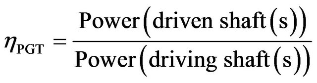
The function of a vehicle transmission is to adjust the traction available at the output shaft of the drive engine to suit the vehicle, the surface, the driver and the environment. One of most important decisive effect of the transmission is the fuel consumption. The need of reducing the fuel consumption has become nowadays a very important factor. Historically, to meet this objective, vehicles are usually equipped with gearboxes with more ratios while adjusting at best the situation of the ground to cross with the drive engine regime. The major drawbacks concerning gearboxes can be linked to the holes when moving from one report to another, and to the large number of ratios that have to be installed, especially for heavy vehicles. A way that could overcome these disadvantages, at least partially, is a continuously variable transmission using a speed variator that permitting to vary the output speed continuously, eliminating the discontinuity in the speed variation. However, these transmissions are limited in use due to their low capacity transmission. A best solution, which seems to be the most effective, consists in the use of continuously variable power split transmissions (CVPST), or infinitely variable transmission (IVT) ensures a continuously ratio transmission and an infinite ratio range. These kinds of transmissions are mainly composed of one or more planetary gear trains (PGT), a unit of speed variator (Continuously Variable Unit, CVU) and one (or more) ordinary gear trains with fixed ratio (FR). It should be noted that a classical planetary gear train operates with two degrees of freedom and three running shafts. The unit speed variator (CVU) carries out the control by imposing an angular velocity on one of the three running shafts of the PGT. These continuously variable transmissions are classified into two main categories: The case of transmission “Input-coupled (IC)”, (Figure 1) in which one shaft of CVU is connected to the input one of the transmissions while the “Output-Coupled, OC”, (Figure 2), corresponds to the case of that one shaft of the CVU is related to the output one of the transmission [1]. Taking into account of the direction of power flow that can occur between the three components, these transmissions are classically divided into three types for the case “IC” (Figure 1) and three others for the case “OC”: Type I, Type II and Type III, (Figure 2) [1,2].
It should be noted that the planetary gear train plays a fundamental role in the setting up of these power split transmissions. Its efficiency, which could be very low for some operating conditions, is a major factor in the performance assessment of the transmission in which the PGT is integrated. Some authors have considered this efficiency as constant for the whole modeling in the total transmission efficiency. Yan and Hsiech [1] and Schembri et al. [2] performed a preliminary analysis of two classes, Input-coupled and Output-Coupled, used in an infinitely variable transmission considering the efficiency
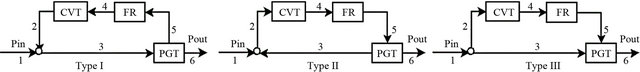
Figure 1. Power flow type in the case of (IC).
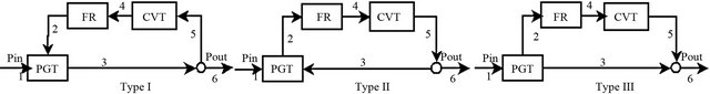
Figure 2. Power flow type in the case of (OC).
of the PGT constant as the same as for the CVU and FR. Mantriota et al. [3-5] have used an approach presented by Pennestri et al. [6]. In Ref [6] the authors considered the planetary gear train as composed of two ordinary gear mechanisms, and, the efficiency of the PGT is computed basing on this assumption. In this work, our objective is to establish the overall efficiency of the transmission, based on a simple algorithm to assess the mechanical efficiency of planetary gear trains which operate as differential mechanism [7]. This paper aims also to compare ours results with those available in the literature, otherwise obtained by other approaches. In order to illustrate the strengths of the present approach, two comprehensives applications are presented. The first deals with a continuously variable transmission consisting of a speed variator, a mechanism gears with fixed ratio and a planetary gear trains of Type I [8]. The second is the same as the first, the difference lies in the type planetary gear train which is of Type IV [8]. These transmissions can perform as continuously variable power split transmissions (CVPST), or infinitely variable ones (IVT), according to the type of powers flow required by the design variables. Let τPGT, τFR and τCVT be the stationary gear ratio of the PGT, the ratio of the ordinary gear and speed ratio of the variator, respectively.
As for organization of the paper, the next sections present all the basic elements we have adopted in this work, namely the efficiency of a PGT which is the central and the efficiency of the variator component of the transmission. The fifth section describes the proposed algorithm, to estimate the overall efficiency of the transmission for different configurations, basing on a kinematic and energetic analysis. Some applications with results compared with the literature are reported in Section 6. Finally, some concluding remarks in the last section.
2. Efficiency of Planetary Gear Trains
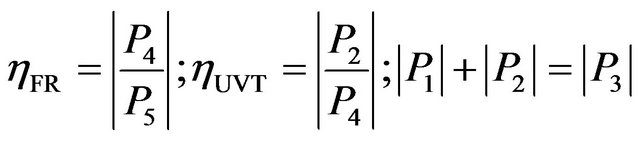
In this work, planetary gear trains (PGT), characterized by its stationary gear ratio τPGT, operates with two degrees of freedom and comprise two suns gears (i) and (j), a carrier (k) and planets (S). It should be noted here that one or the two sun gears can be ring(s). Let ωi, ωj and ωk be, respectively, the angular velocities of the two suns gears (i, j) and the carrier (k), respectively. Similarly, we denote by, Ti, Tj and Tk torques on the links (i), (j) and on the carrier shaft (k), respectively. Let Pi, Pj and Pk be the powers on the sun gear (i), the sun gear (j) and on the carrier (k), respectively. We gather all equations and relationships useful in the determination systematically of the mechanical efficiency of a PGT:
• Willis’ equation:
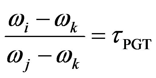 (1)
(1)
• Equilibrium equation:
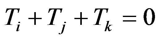 (2)
(2)
• Powers on the three running shafts (i, j, k):
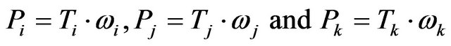 (3)
(3)
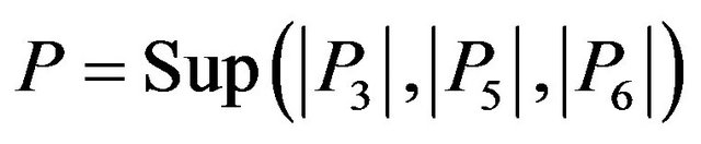
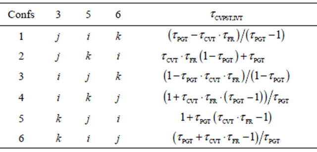
• The greatest power (P) of the three powers that crosses the three running shafts of the PGT. Each index i, j and k can take the values 3, 5 and 6 (Figure 3 and 4), according to the configuration of the transmission (see Table 1):
 (4)
(4)
• The relative power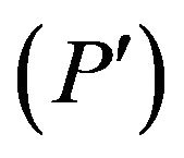 , defined in the relative movement, such as:
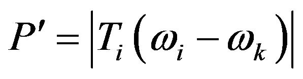 or
or 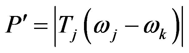 (5)
(5)
• The exponent q can have the values 1 or −1, according to the sign of the power ratio following [7]:
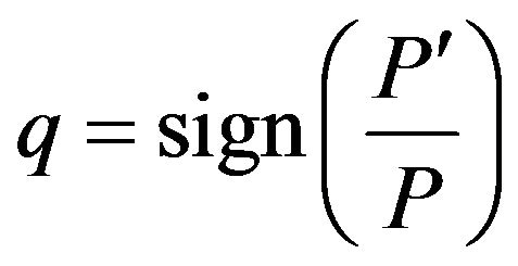 (6)
(6)
• The mechanical efficiency of the PGT id defined by the ratio of the power on receiver shaft(s) by the
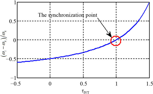
Figure 3. Speeds ratio (PGT with Type IV).
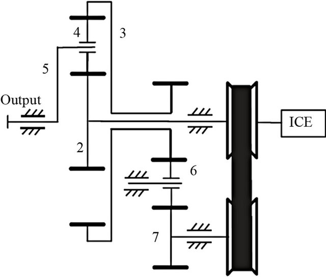
Figure 4. CVPST model according to [10].
Table 1. Transmission ratio in the six possible connection arrangements in a planetary gear trains.
power on drive one(s):
 (7)
(7)
• A power which comes to the PGT block is counted algebraically positive (driving(s) shaft(s)) and a power that leaves is counted negative (driven(s) shaft(s)).
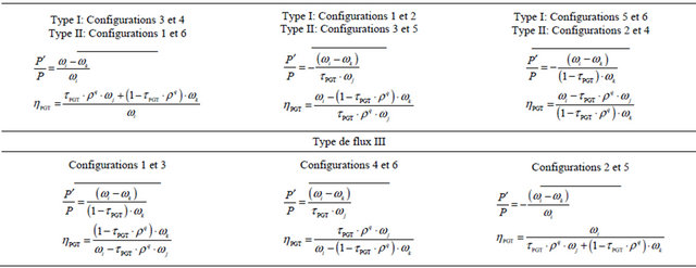
Finally, analytic expressions of the mechanical efficiency of a given PGT, with respect to the power flow, the sign of the exponent (q) and the configurations are reported in Table 2. The configurations of the PGT, which determine the input, output and floating shafts (Figure 1) are illustrated in Table 1 below.
3. Power Flows
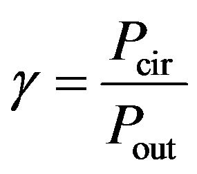
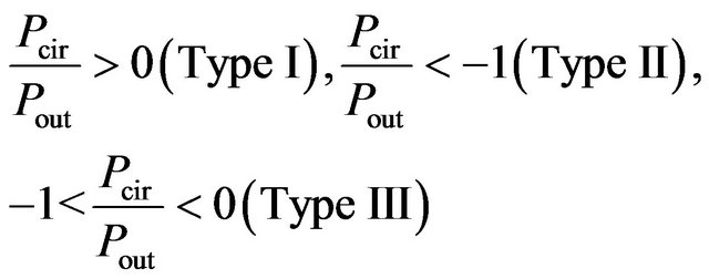
An important factor in power flow analysis within power split transmissions, called factor of power flow, is adopted to identify the type of power flows [9] (Figures 1 and 2). The type of power flow is conventionally defined by the ratio of the power through the control circuit 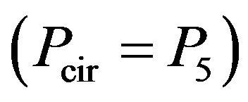 by the output power (Pout) [10,11]. In the case of IC, where the power at the entrance noodle of the transmission is divided in two parts, the first across over the control branch through FR and CVU, as for the second directly into the PGT. The last behaves as a power collector (Figure 1, Type III). In this case of operating, the transmission behaves as a power split transmission. In the two other cases, the power flow leading to a power recirculation (Figure 1, Type I, II). According to Figures 1 and 2, transmissions with a Type III power flow are more desirable because there is no power recirculation in the transmission circuit. In Type I and Type II power flows, certain transmission components are exposed to a power load greater than that of the input load. Distinction between the three power types could be made thanks to the so-called circulating power factor, defined by [9-11]:
 (8)
(8)
According to the operating conditions, the three power flow Types I, II and III are defined by the following statements:
 (9)
(9)
4. Variator Efficiency
The variable element in this transmission is responsible for the greatest part of the mechanical losses because it is less efficient than conventional gears [9]. The type of variable element chosen for this particular application was the metal pushing belt CVU because it offers acceptable efficiency values compared to other variable elements [3, 5].
The efficiency of the CVU is computed according to the operating conditions. There are a number of papers in the literature, on experimental studies on the efficiency of V-belt. Using this Experimental results presented in [3], derived from a series relations to compute the efficiency of CVU, which interpolates the experimental data according to the input torque of the CVU, the angular velocity of the driving pulley CVU, and the overall ratio of the transmission. In this work, the curves (Figures 5
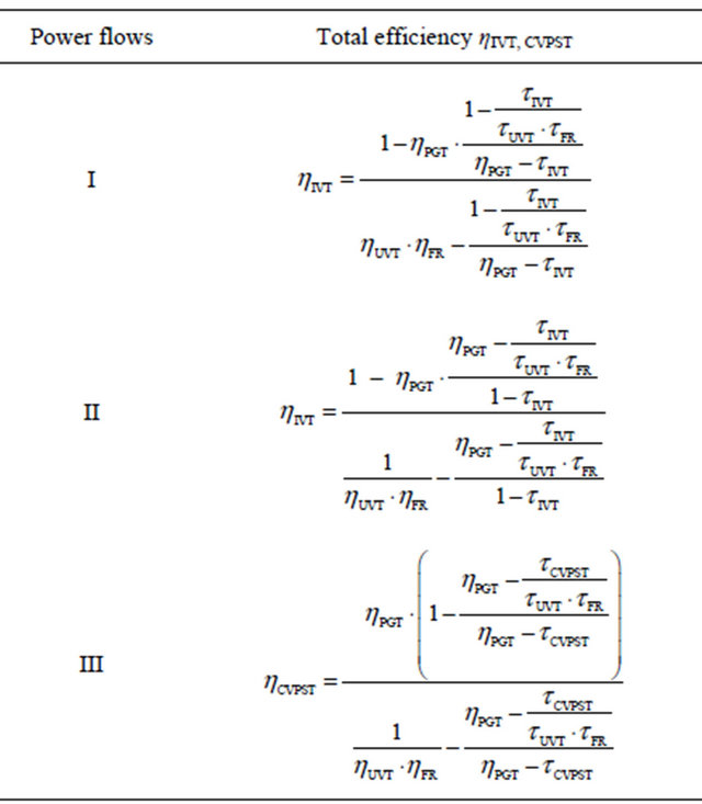
Table 2. Mechanical efficiency of the PGT for the three power flow types and configurations.
and 6) related to the transmission ratio τIVT, refer to a specific value of the dimensionless output torque t. The parameter t points out, for every value of τIVT, the ratio between the IVT output torque  and the transmissible maximum torque
  in condition of nonglobal sliding of the CVU [5].
5. Overall Efficiency of the Transmission (IC)
Efficiency is a priority factor in the study of CVPSTs (IVTs). So, estimating the efficiency of a pre-designed variable transmission is a very important issue, as this will determine the prospective performance and the feasibility of the final design and the eventual prototype. Yan and Hsieh [1] and subsequent integrations by Mangialardi and Mantriota [12], Zhang and Leduc [13] and S. Schembri et al. [2] have examined the efficiency of an IVT assuming that the efficiency of the CVU ηCVT and the planetary gear train ηPGT are constant. Mangialardi and Mantriota [3-5] applied the method for computing the efficiency of a PGT developed by Pennestri et al. [6], which is not systematic and its application to more complex models of transmissions would be rather cumbersome. The CVPST (IVT) system efficiency is a function of the individual component efficiencies and the ratio of power flowing through the individual branches of the system. Often the performance of a CVU is improved by coupling it to a planetary gear train. Knowing that CVUs have generally a lower efficiency than PGTs, the best performance is obtained with a low ratio of power through the variable branch. Therefore, the flow Type III promotes high transmission efficiency and low dissipation due to the power recirculation. In addition, dimensions of CVUs are strictly related to the maximum power and torque required during the operating conditions. So that this type of flow leads to more technological solutions are more
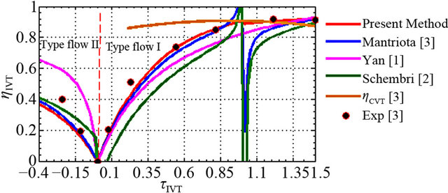
Figure 5. Total efficiency of the transmission with respect the transmission ratio (t = 1).
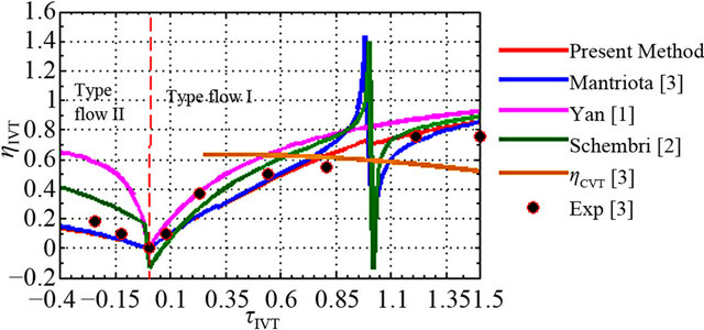
Figure 6. Total efficiency of the transmission with respect the transmission ratio (t = 0.2).
compact. This work looks for configurations that the most suitable type of operation, knowing that the overall efficiency of the transmission function is a weighted performance of the planetary gear and that of the CVU. The weights are the weight fractions of power through the CVU and the PGT. In this study, we provide in the first step one algorithm of calculating the efficiency of the PGT (Section 2), then the overall efficiency equation of the transmission for different configurations of power flow Types I, II and III of the input-coupled architecture (IC) (Table 3).
With a Type I power flow, in steady state, with ηPGT denoting the efficiency of the PGT train; based on the
Table 3. Total efficiency of the transmission according to power flow type.
power equation we have (Figure 1):
 (10)
(10)
Namely: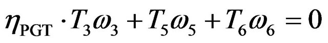 (11)
(11)
The equilibrium of the torques acting on the shafts of the PGT train is:
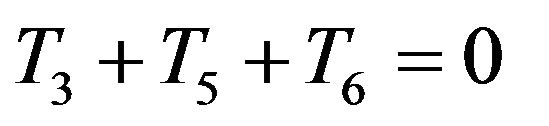 (12)
(12)
Thereby: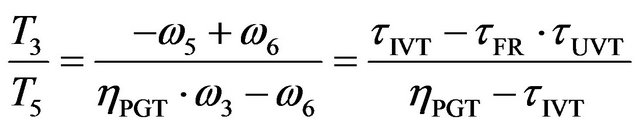 (13)
(13)
Hence: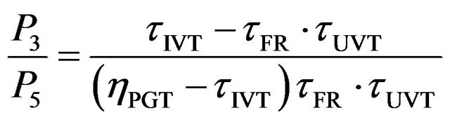 (14)
(14)
Moreover (Figure 1, Type of power flow I)
 (15)
(15)
with ηFR and ηUVT denoting the efficiency of the FR mechanism and of the CVU. Through these equations it is possible the determination of the parameters that characterize the performances of the CVPST (IVT).
A systematic algorithm to compute the mechanical efficiency of CVT (CVPST, IVT): An algorithm to calculate the mechanical efficiency of a given CVT is developed and proposed here. This algorithm consists in the following steps:
1) The PGT, CVU and FR are respectively identified by their characteristics values (τPGT, ρ), (τUVT, ηUVT) and (τFR, ηFR) respectively (to calculate ρ see Ref [14]);
2) Identify the configuration (Table 1);
3) For the kinematic situation, identify the types of power flows I, II or III by drawing the ratio 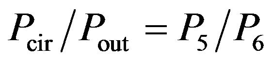 according to τIVT, CVPST or τUVT (Equation (8));
4) The type(s) of power flow is now determined, identify then the sign of the exponent “q” thanks to formulas provided in Table 2. The mechanical efficiency of the PGT can be calculated easily, using the Table 2, where all possible cases are illustrated;
5) The overall mechanical efficiency of CVT can be calculated easily using the Table 3.
In order to achieve the desired objective, by making more concrete the proposed algorithm on the mechanical efficiency of CVTs. once the type of transmission has been established. We are going to deal with two different applications.
6. Results and Discussion
In order to determine the performance of an overall architecture (IC) for different approaches, we propose two case studies of variable transmissions offered by the authors [3-5,9-11].
6.1. Application I
In this application, we consider a continuously variable transmission used in [9-11], it includes a simple PGT Type I [8] with three running shafts, a belt variator and an ordinary gear train (see Figure 4). It has the following characteristics:
• a belt mechanical variator with a speed ratio τCVU that varies between 0.5 to 2.5, and an efficiency ηCVU which is estimated at an average 0.8;
• a PGT with a gear ratio (τPGT = −3), its efficiency ηPGT will be calculated here;
• An ordinary gear with a constant ratio τFR = 2 and efficiency ηFR = 0.98.
Figure 7 shows an example of how the configuration may affect the overall transmission ratio, or a configuration is a layout of the elements of architecture. For certain configurations, the overall transmission ratio may even become negative, so, it gets to lockup point (τIVT = 0), thereby reversing the rotation of the output shaft. Furthermore, τCVU and τIVT may become directly or inversely proportional. In this locus, there will be change of power flow (see Figure 8, Conf 5 and 6). Another interesting consideration is that if the value (τCVU = 0.5), regardless of the configuration, value for CVPST (IVT) transmission ratio is equal the unit (Synchronization point).
Figure 8 shows that the curves of total efficiency are slightly different for various models. We noted that this
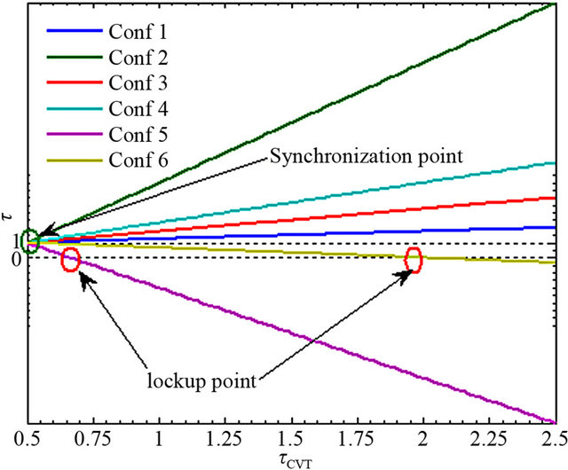
Figure 7. The ratio of transmission with respect to the CVU ratio change for all six configurations.
efficiency does not exceed 80% for configurations 2, 4 and 5 except for configurations 1 and 3 that it can reach more than 90%. This observation could be caused by the fact that most of the energy flow runs through the PGT (power flow Type III). At the point of change of power flow, the efficiency decreases rapidly until it canceled out at the lockup point.
6.2. Application II
In this case, we consider also an infinitely variable transmission that is composed of a PGT, an ordinary gear train, but, the PGT is Type IV (Figure 9) [8]. This case was studied by [3-5]. The total transmission ratio is supposed to be such as τIVT = [−0.5 2.5]. The other characteristics of the transmission are:
• for the V-belt variator: τCVU = [0.5 2.5];
• for the PGT ratio: τPGT = 2;
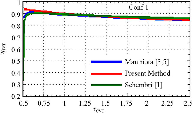
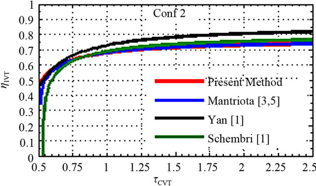
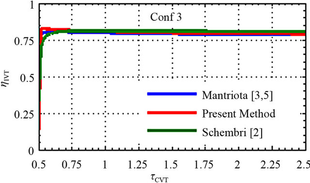
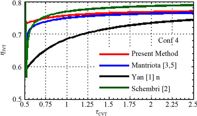
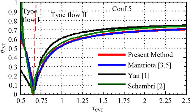
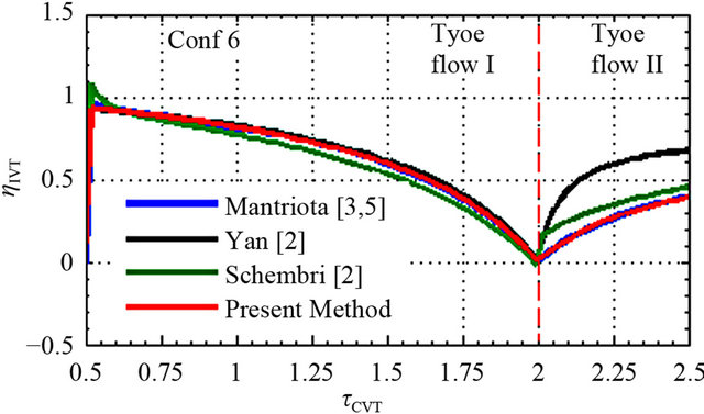
Figure 8. Total efficiency of the transmission for different models.
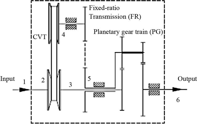
Figure 9. Model IVT [3].
• And for the ordinary gear efficiency and ratio: ηFR = 0.98; τFR = 1.
The present transmission is different from the previous; indeed, the type of a PGT used in this application is IV [8], which influences the efficiency of the transmission. Once the direction of the power flows for each coupling is known (Figure 10), the efficiency as a function of the transmission ratio can be computed. Thus, once the velocity of the shafts of the gear train and the power circulating in one of the shafts are known, the efficiency ηPGT may be determined. In fact, for the PGT with Type I (application I), the speed ratio of the running shafts of PGT has not changed sign for all configurations, on the other hand, for the second application where a PGT Type IV is used, this ratio changes in sign. The sign change of the speed ratio of shafts of the PGT involves the passage by the synchronization point for what τIVT = 1 (Figure 3). At this situation, the exponent q also changes sign, which explains the discontinuity of the efficiency of PGT (τIVT = 1); and this efficiency in the left and in the right of this point is not the same, but it is equal to unit at the same point. In fact, the three running shafts of the PGT rotate with the same speed and so there is no relative movement between gears; we found out the same behavior again, so the relative velocity between components is zero. This finding is shown by the present method (Figure 11). In fact Pennestri et al. [13] have only provided the efficiency of PGT, while the global models are further developed in this work modeled the global efficiency of the IVT and are expressed in terms of the PGT efficiency corresponding at that model. For a more profitable evaluation of the IVT performances, the IVT efficiency in relation to the transmission ratio variations for two different values of the dimensionless torque (t = 1, 0.2) is shown in Figures 5 and 6. Figure 5 compares the total efficiency of the transmission computed by our model to other literature ones such as Yan et al. [1], S. Schembri et al. [2], G. Mantriota [3] and experimental study [3]. The values shown in Figure 5 are related to the unitary value of the dimensionless output torque (t = 1). We
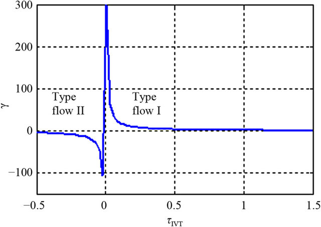
Figure 10. Powers ratio (type power flows).
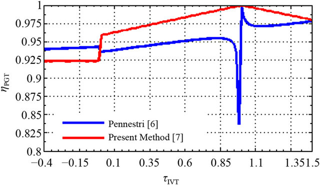
Figure 11. Efficiency of planetary gear train as function of τIVT.
found that the present method has the same shape as the other, with an advantage that is best in most situations of operating, and that overall efficiency is discontinuous at the synchronization point. It is better for transmission ratios greater than 1, low at the velocities of the lockup point and it is null at this point. Finally, in general, the efficiency is better for the flow with Type I as Type II. The theoretical curves shown in Figure 6 ([3], Present Method) were obtained by means the theoretical model, in which ηCVU was calculated using the interpolated curve of the efficiency of the CVU in Ref [3], while the efficiency of the FR mechanism was considered constant (ηCVU = 0.98) and ηPGT was calculated through the models shown in Ref [6] and the Subsection 2. From Figure 6 (t = 1) emerges that the IVT efficiency grows with the growth of the transmission ratio and overcomes that of the CVU for τIVT ≥ 0.8. For τIVT < 0 the efficiency grows more slowly compared to the first part of the curve obtained for τ > 0. In comparison to the preceding case (Figure 5), an ampler interval in which ηIVT is greater than ηCVU and a larger gap is noticed among ηIVT and the experimental efficiency. This result is justifiable observing that the incidence of the other component losses (PGT, FR) decreases, because compared to the CVU; their efficiency is less influenced by the torque reduction.
7. Conclusion
We have presented a systematic algorithm for calculating the overall mechanical efficiency of a given CVT, integrated a planetary gear trains. The CVT efficiency is strongly influenced by the entity of the fraction of power that crosses the control branch, it is maximum when the type of power flow is III. This approach is generic and illustrations were presented to demonstrate its applicability to various configurations that have practical significance in automotive applications and other fields. This research has been written with the aim of laying out a set of concepts which would aid in classifying and understanding CVT transmissions, as well as to present a general scheme for their depiction in terms of performances. Finally, the efficiency of the transmission change considerably as the transmission ratio changes, such as at the lockup point there is still a change of power flux, and at the synchronization point, we noticed a fluctuation in the efficiency of other models while our remained steady. Hence it is plausible that considerable changes may occur in the efficiency of the elements constituting the CVT as the operating conditions (power, transmission ratio, angular velocity, torque) change, thereby affecting the overall efficiency of the transmission. We can see from the obtained results that a detailed evaluation of the efficiency of CVT components allows us, in relation to the operational conditions, to obtain a good evaluation of the CVT performances through the our theoretical model. The result of this work is beneficial to engineers for preliminary design continuously variable transmissions with maximum mechanical efficiency.
REFERENCES
- H.-S. Yan and L.-S. Hseich, “Maximum Mechanical Efficiency of Infinitely Variable Transmissions,” Mechanism and Machine Theory, Vol. 29, No. 5, 1994, pp. 777-784. doi:10.1016/0094-114X(94)90120-1
- S. Schembri Volpe and G. Carboni, “Design Optimization of Imput and Output Coupled Power Split Infinitely Variable Transmission,” ASME Journal of Mechanical Design, Vol. 131, 2009, pp. 1-11.
- G. Mantriota, “Performance of a Series Infinitely Variable Transmissions with a Type I Power Flow,” Mechanism and Machine Theory, Vol. 37, No. 6, 2002, pp. 579-597. doi:10.1016/S0094-114X(02)00017-4
- G. Mantriota, “Performance of a Parallel Infinitely Variable Transmission with a Type II Power Flow,” Mechanism and Machine Theory, Vol. 37, No. 6, 2002, pp. 555-578. doi:10.1016/S0094-114X(02)00018-6
- L. Mangialardi and G. Mantriota, “Power Flows and Efficiency in Infinitely Variable Transmissions,” Mechanism and Machine Theory, Vol. 34, No. 7, 1999, pp. 973-994. doi:10.1016/S0094-114X(98)00089-5
- E. Pennestri and F. Freudeinschein, “The Mechanical Efficiency of Epicyclic Gear Trains,” ASME Journal of Mechanical Design, Vol. 115, No. 3, 1993, pp. 645-651. doi:10.1115/1.2919239
- A. Aittaleb, A. Chaâba and M. Sallaou, “On the Mechanical Efficiency Assessment of Planetary Gear Trains: Analytic Formulas and an Easy Algorithm,” Mechanism and Machine Theory (Submitted).
- G. Henriot, “Traité Théorique et Pratique des Engrenages,” Dunod, Paris, 1979.
- A. J. Fox, “Design and Analysis of a Modified Power Split Continuousely Variable Transmission,” Master Thesis, Univercity, Morgantown, 2003.
- V. H. Mucino, Z. Lu, J. E. Smith and B Cowan, “Design of Continuously Variable Power Split Transmission Systems for Automotive Applications,” Mechanical Engineers, Vol. 215, 2001, pp. 469-478.
- Z. Lu, “Acceleration Simulation of a Vehicle with a Continuously Variable,” Faculty of the College of Engineering and Mineral Resources, West Virginia University, Morgantown, 1998.
- L. Mangialardi and G. Mantriota, “Comments on Maximum Mechanical Efficiency Infinitely Variable Transmissions,” Mechanism and Machine Theory, Vol. 33, No. 4, 1998, pp. 443-447. doi:10.1016/S0094-114X(97)00037-2
- Y. Zhang and B. Leduc, “Efficiency Predetermination of Planetary Trains Used as Continuously Variable Transmission,” European Journal of Mechanical Engineering, Vol. 37, 1992, pp. 169-173.
- E. Pennestrì, L. Mariti, P. Valentini and V. H. Mucino, “Efficiency Evaluation of Gearboxes for Parallel Hybrid Vehicles: Theory and Applications,” Mechanism and Machine Theory, Vol. 49, 2012, pp. 157-176. doi:10.1016/j.mechmachtheory.2011.10.012
NOTES
*Corresponding author.